海利普C系列变频器说明书
- 格式:pdf
- 大小:485.45 KB
- 文档页数:47

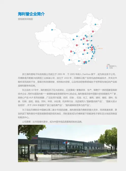
海利普企业简介营销服务网络图*图注红:销售服务中心蓝:办事处浙江海利普电子科技有限公司成立于2001年,于2005年纳入Danfoss旗下,成为其全资子公司。
丹佛斯是丹麦最大的跨国工业制造公司,创立于 1933年,丹佛斯以推广应用先进的制造技术,并关注节能环保而闻名于世,是制冷和空调控制,供热和水控制,以及传动控制等领域处于世界领先地位的产品制造商和服务供应商。
在过去的10年中,海利普经历了巨大的变化,已发展成一家集研发、生产、销售于一体的国家级高新技术企业,同时也是国内唯一一家拥有省级变频研发中心的企业。
海利普是目前中国最大的变频器生产厂家,其核心产品HLP系列变频器,广泛应用于起重、纺织、印染 、石油、化工、建筑、建材、橡胶、塑料、包装、印刷、造纸、食品、饮料、环保、水处理、机床等行业,先后被列入“国家重点新产品”、 “国家火炬计划项目”,并于2004年被授于“浙江省名牌产品”、“国内最具有竞争力的产品”。
为了适应丹佛斯在中国建立第二家乡市场的战略,海利普依靠丹佛斯的强大支持,寻求高速发展,更加巩固了海利普在中国变频器领域的领先地位,同时逐渐成为丹佛斯旗下的能源电子部在亚太地区的制造和物流中心。
公司愿景:比市场增长更快,成为中国市场品质最高的知名品牌。
目录通用型变频器HLP-A通用型变频器 / 4HLP-C+迷你型变频器 / 12矢量型变频器HLP-B高性能矢量型变频器/ 17HLP-NV矢量型变频器 / 24专用型变频器HLP-P风机/水泵专用变频器 / 30 HLP-H中频机 / 36HLP-F纺织专用变频器 / 40HLP-J注塑机专用变频器 / 43HLP-CP跑步机/手套机专用变频器 / 47 HLP-M机床专用变频器 / 51常用选配件直流电抗器 / 55交流输入/输出电抗器 / 55输入/输出滤波器 / 57制动单元与制动电阻 / 57接线用断路器及漏电开关 / 58电磁接触器及浪涌吸收器 / 59隔离变压器 / 59 海利普变频器 系列产品本产品为通用型变频器,软件功能强大,具有多种控制方式;内置PID、简易PLC;输出转矩高(150%/1分钟),过载能力强,广泛应用于编织、化纤、印染、塑料、轻工、机械、化工、钢铁、造纸等各种行业,并受到用户的一致好评。
HLP-C100系列海利普变频器操作指南一、前言HLP-C100系列海利普变频器是一款高性能、矢量控制型变频器,广泛应用于各种自动化控制系统中。
为了帮助用户更好地了解和熟练使用本产品,我们特制定本操作指南。
二、开箱及检查1. 请确保在运输过程中变频器外观无明显损坏,附件齐全。
2. 检查装箱单,确认购买的变频器型号、规格及配件是否与需求相符。
3. 取出变频器,检查外观是否有划痕或损坏,紧固件是否齐全。
三、安装1. 请将变频器安装在干燥、通风良好、无腐蚀性气体和尘埃的环境中。
2. 确保变频器安装平面平整,便于散热。
3. 接线前请务必断开电源,按照接线图连接输入输出线路。
4. 连接地线,确保地线连接可靠。
四、设置1. 开机后,变频器默认进入运行模式。
如需进行参数设置,请按住"SET"键,然后按"↑"或"↓"键选择需要设置的参数。
2. 通过按"↑"或"↓"键调整参数值,按"SET"键确认并保存设置。
3. 部分参数需要重启变频器后才能生效。
五、操作1. 启动:按下启动按钮,变频器开始运行。
2. 停止:按下停止按钮,变频器停止运行。
3. 急停:在运行过程中,如遇到紧急情况,请及时按下急停按钮,确保设备安全。
六、维护与故障排除1. 定期检查变频器内部和外部连接线路,确保无异常情况。
2. 检查散热器是否正常工作,如有异常,请及时清理或更换。
3. 如发现变频器工作异常,请参照故障排除指南进行排查。
七、安全注意事项1. 在操作变频器时,请务必遵守相关安全规定,确保人身和设备安全。
2. 请勿将液体、金属物体等导电物品靠近变频器。
3. 操作人员应具备一定的电气知识,如无相关经验,请谨慎操作或寻求专业人员帮助。
八、售后服务1. 本产品自购买之日起,享受一年内有偿保修服务。
2. 保修期内外,如遇到问题,请及时与我们联系,我们将竭诚为您提供技术支持和维修服务。

HLP-C100系列海利普变频器操作指南
简介
本操作指南为HLP-C100系列海利普变频器的用户提供了详细
的操作说明和使用方法。
变频器是一种用于控制电机转速的设备,
通过调整电机的频率和电压来实现对电机运行状态的控制和调节。
操作步骤
1. 开机:确保变频器与电源连接正常,打开电源开关,变频器
将自动启动。
2. 参数设置:按照所需的转速和运行模式,设置变频器的参数。
具体参数设置方法请参考变频器的用户手册。
3. 运行控制:根据需要调整变频器的运行模式和运行频率,以
达到所需的电机转速。
4. 故障排除:如果发生故障或异常,可以通过变频器的故障代
码和报警指示灯来判断故障原因,并采取相应的措施进行排除。
注意事项
- 在操作变频器之前,请确保已经详细阅读并理解了变频器的
用户手册和安全注意事项。
- 在进行参数设置和操作调节时,请确保断开电源并等待足够长时间,以确保电容器中的电荷已经消散,避免触电危险。
- 在变频器运行过程中,应定期检查温度和电流等参数,确保变频器正常工作,并及时处理异常情况。
以上是HLP-C100系列海利普变频器的操作指南,希望能对用户在使用过程中起到一定的指导作用。
如需更详细的信息,请参考变频器的用户手册或联系相关技术支持部门。
海利普变频器HLP-C100系列用户手册1. 引言欢迎使用海利普变频器HLP-C100系列。
本用户手册旨在为您提供详细的使用说明和操作指南,以确保您能够充分利用该产品的功能和特性。
2. 产品概述HLP-C100系列变频器是一种高性能的电气控制设备,可将输入电源的频率和电压转换为适合驱动电机的输出信号。
该系列产品具有稳定可靠、节能高效等特点,广泛应用于工业自动化领域。
3. 安装与连接3.1 安装要求在安装HLP-C100变频器之前,请确保满足以下要求:- 安装位置应干燥、通风良好,并远离高温、潮湿和腐蚀性气体的环境。
- 安装面应平整牢固,以确保设备的稳定运行。
- 请按照产品说明书正确连接输入和输出电源。
3.2 连接电机连接电机时,请遵循以下步骤:1. 确保电机和变频器之间的电缆连接正确无误。
2. 根据电机的额定参数设置变频器的相关参数。
3. 确保电机转向正确,可以通过手动启动变频器进行测试。
4. 使用说明4.1 参数设置在使用HLP-C100变频器之前,您需要正确设置一些参数,以适应不同的工作场景。
请参考以下步骤进行参数设置:1. 进入参数设置界面。
2. 根据实际需求,设置输入和输出电压、频率等参数。
3. 保存设置并退出参数设置界面。
4.2 运行控制HLP-C100变频器提供多种运行控制方式,以满足不同的应用需求。
您可以选择以下其中一种方式进行运行控制:- 通过面板按键进行手动控制。
- 通过外部信号进行远程控制。
- 通过通信接口与上位机进行通讯控制。
5. 故障排除在使用HLP-C100变频器过程中,可能会遇到一些故障情况。
请参考以下常见故障排除步骤进行处理:1. 检查电源是否正常供电。
2. 检查电缆连接是否松动或损坏。
3. 检查参数设置是否正确。
4. 如果以上步骤无法解决问题,请联系售后服务。
6. 维护与保养为了确保HLP-C100变频器的正常运行和延长使用寿命,请遵循以下维护与保养要求:- 定期清洁设备表面,防止灰尘和杂物积累。
HLP-C+/CP系列使用说明书HLP-C+/CP系列目录一、前言……………………………………………………1 1、购入时注意事项……………………………………………… 2 2、H LP- C+/CP系列铭牌说明………………………………… 3 二、安全使用注意事项………………………………·…4 1、送电前………………………………………………………… 4 2 、送电中………………………………………………………… 6 3、运转中………………………………………………………… 6 三、产品 标 准 规 格 ………………………………………7 1、产 品 个 别 规 格 …………………………………………………7 2 、产 品通 用 规 格 …………………………………………………7 四、储 存及 安 装 ………………………………………… 9 1、储 存 …………………………………………………………… 9 2 、安 装 场所与 环 境……………………………………………… 9 3、安装空间与方向………………………………………………10 五、配 线…………………………………………………11 1、主回路配线图…………………………………………………11 2、接线端子说明…………………………………………………12 3、基本配线图……………………………………………………13 4、配线注意事项…………………………………………………15 六、数位操作器说明…………………………………… 17 1、数位操作器说明………………………………………………17 2、指示状态显示说明……………………………………………17 3、操作说明………………………………………………………18HLP-C+/CP系列使用说明书HLP-C+/CP系列 七、试运行……………………………………………… 19 1、运行前检查……………………………………………………19 2、试运行方式……………………………………………………19 八、功能一览表………………………………………… 20 九、功能说明…………………………………………… 27 十、保养 维护、故 障信息 及 排除 方法…………………73 1、维护检查注意事项……………………………………………73 2、定期检查项目…………………………………………………73 3 、故 障 信 息 及 故 障 排 除 ……………………………………… 7 4 4、故障及分析……………………………………………………77 十一、周边设施选用及配置……………………………79 1、选件……………………………………………………………79 2、配置……………………………………………………………80 十二、附录……………………………………………… 81 附 录一:简单 应 用 举 例…………………………………………81 附录二:机器外型及安装尺寸…………………………………83 附 录 三:C + / C P系 列键 盘 操 作及 实例…………………………8 5 附录四:使用者记录及反馈……………………………………87 附录五:HLP-C+和CP系列特殊机种说明………………… 90HLP-C+/CP系列使用说明书HLP-C+/CP系列一、前言 欢迎使用HLP- C+系列多功能、高性能通用变频调速器。
海利普变频器HLP-C100系列操作手册一、简介海利普变频器HLP-C100系列是一款高性能、通用型变频器,适用于各种场合的交流电机调速。
本操作手册提供了有关HLP-C100系列变频器的详细操作说明,包括安装、接线、参数设置、操作和故障处理等。
二、安装与接线1. 安装1. 将变频器安装在干燥、通风良好、无腐蚀性气体和尘埃的环境中。
2. 确保变频器的工作电压与被控电机的额定电压相符。
3. 遵循变频器接线图进行接线,确保接线正确无误。
2. 接线1. L、N端子接电源线,U、V、W端子接电机线。
2. 接好地线,确保安全。
3. 如需外接控制信号,请根据接线图连接相应的控制信号线。
三、参数设置1. 启动模式1. 短接STOP和RUN端子,将变频器置于手动控制模式。
2. 通过面板上的方向键和确认键,设置参数。
2. 参数设置四、操作1. 启动1. 接通电源,确保变频器面板上的POWER指示灯亮起。
2. 通过面板按键或外部控制信号,启动电机。
2. 停止1. 通过面板按键或外部控制信号,停止电机。
五、故障处理1. 常见故障2. 故障排除1. 参照故障现象和可能原因,进行故障诊断。
2. 根据诊断结果,采取相应的处理方法。
六、注意事项1. 在操作变频器前,请确保已切断电源,以免发生意外。
2. 请勿将变频器暴露在高温、潮湿、腐蚀性气体和尘埃环境中。
3. 定期对变频器进行维护,确保正常运行。
七、技术支持如在使用过程中遇到问题,请随时与我们联系,我们将竭诚为您提供技术支持。
电话:400-xxx-xxxx地址:xxx。
HLP-C100系列海利普变频器指南1. 简介HLP-C100系列海利普变频器是一款高性能、矢量控制型变频器,广泛应用于各种电机控制场合。
本指南将为您详细介绍HLP-C100系列海利普变频器的安装、调试、运行和维护方法。
2. 安装2.1 准备工作在安装变频器前,请确保以下准备工作已完成:1. 确保电源、负载和控制电路的正常运行。
2. 准备合适的工具,如螺丝刀、扳手等。
3. 了解变频器的接线图和接线说明。
2.2 安装步骤1. 将变频器放置在通风、干燥、清洁的环境中。
2. 按照接线图,连接变频器的输入输出线路。
3. 固定变频器到合适的安装位置。
4. 连接变频器的外部控制线路。
5. 连接变频器的通讯接口(如需)。
3. 调试3.1 参数设置1. 开机后,进入参数设置界面。
2. 根据实际应用需求,设置相关参数,如电机参数、运行参数、保护参数等。
3. 保存并退出参数设置界面。
3.2 空载运行1. 确保电机与负载连接正确。
2. 开启变频器,观察电机是否正常运转。
3. 检查电机运行参数,如转速、电流等,是否符合预期。
3.3 负载运行1. 逐渐增加负载,观察电机在不同负载下的运行情况。
2. 调整变频器参数,优化电机运行性能。
3. 检查电机在负载运行过程中的参数稳定性。
4. 运行4.1 日常检查1. 检查变频器电源、输入输出线路是否正常。
2. 检查变频器运行参数是否异常。
3. 检查电机运行状态,如温度、振动等。
4.2 定期维护1. 定期清理变频器内部的灰尘。
2. 检查变频器散热系统是否正常。
3. 检查变频器内部电路板、连接线等部件是否有损坏。
5. 故障处理当变频器出现故障时,请按照以下步骤进行处理:1. 分析故障现象,如报警代码、运行参数等。
2. 查阅故障手册,确定故障原因。
3. 按照故障手册的建议,进行故障排除。
4. 若无法解决问题,请联系海利普技术支持。
6. 安全注意事项1. 在操作变频器时,请确保遵守相关安全规定。
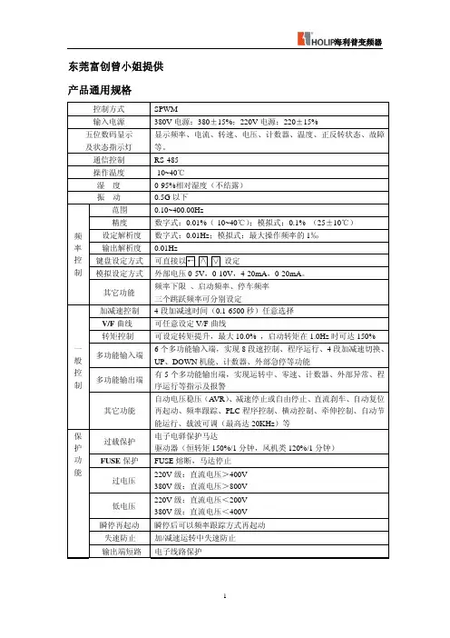
Contents1. Introduction (1)1.1 Confirmations upon delivery (3)1.2 Nameplate information (4)2. Safety Precautions (5)2.1 Before delivery of curren t (5)2.2 In delivery of current (7)2.3 In running (7)3. Inverter standard specifications (8)3.1 Individual specifications (8)3.2 Common specifications (9)4. Storage & Installation (11)4.1 Storage (11)4.2 Location (11)4.3 Position (11)5. Wiring (12)5.1 Main circuit schematic diagram (13)5.2 Terminals (13)5.3 Standard Connection Diagram (14)5.4 Wiring Precautions (15)6. Using the digital operator (19)6.1 Explanations of the digital operator (19)6.2 Display data (19)6.3 Instructions of the digital operator (20)-1-7. Trial Operation (21)7.1 Inspection before operation (21)7.2 Trial operation procedures (22)8. Function List (22)9. Explanations of the functions (30)10. Maintenance, Inspection & Troubleshooting (85)10.1 Precautions about maintenance and inspection (85)10.2 Regular Inspection items (86)10.3 Error information and its troubleshooting (89)10.4 Error and its analysis (90)11. Peripheral devices and specifications of options (90)11.1 Peripheral devices (91)11.2 Proper specifications of options (92)12. Appendices (93)12.1 Application demonstrations (94)12.2 Mounting Dimensions of Inverters (94)12.3 Record and feedback from users (103)Specifications are subject to change without notice for ongoing modifications and improvements.-2-1.IntroductionThank you for purchasing our high quality HLP-C series inverters.HLP-C series frequency conversion governor is developed on the basis of HLP-A series frequency converter,It has kept the main function of A series, increased by some functions according to the request of customer at the same time , have reduced the volume of the machine,So the C series machine has lower volume , the characteristic of stronger function. Before install idiom and operation please read these instructions in this manual thoroughly. For your safety, the product should only be installed, tested and adjusted by professional personnel. If you have any questions or problems, please contact our local agency.High frequency device electric electronic product, for security of you , be sure to install , debugged and changed the parameter by specialized electrical engineering person. Dangerous in this manual, the symbol of noticing etc. reminds your safe precaution item while carrying , installing , operating , checking the frequency converter, please cooperate, make the frequency converter use safer, if there is doubt, the agent who please get in touch with all parts of our company consults, our professional personnel are glad to serve you.The information contained in this manual is subject to change without notice.~WARNING Indicates precautions that, if not avoided, could result in death or serious injury to personnel.-1-!CAUTION Indicates precautions that, if not avoided, could result in minor or moderate injury to personnel and damage to equipment.~WARNING●Always turn off the input power supply before wiring.●Do not touch any inner part of the inverter when the change lamp is still on shortly after the AC power is cut off.●Do not check signals while the inverter is running.●Do not attempt to modify or alter the inverter by yourself, doing so can result in electrical shock or injuryor even explosion.●Be sure to ground the E terminal.!CAUTION●Do not perform voltage withstand tests on the inverter. ●Never connect the AC main circuit power supply to output terminals U.V and W.●A CMOS IC is used in the control board. Handle the control board and CMOS IC carefully. The CMOS IC can be destroyed by static electricity if touched directly.●Installation, testing and maintenance must be performed by professional personnel.●The inverter should be discarded as industrial waste. Avoid burning.-2-1.1 ReceivingBefore unpacking please check the following:●Inspect the entire exterior of the inverter to see there are any scratches or other damage resulting from shipping.●Check if there is inverter and an operation manual in the package as soon as you open the package.●Check the mode on the nameplate on the side of the inverter to see if this is the right model you want.●Check if there is something wrong on the inner parts, wiring and circuit board.●Use a screwdriver to other tools to check for tightness.●Check if there is any other thing in the machine.●Check if the operator buttons are all right.●Check if the optional device you ordered is contained in it.●Check if there is a certificate of qualification and a warranty card.1.2 Nameplate informationMODEL:HLPC01D543AINPUT:3PH380V50/60HzOUTPUT:3PH380V4.0A1.5KWFreq-Range:0.1-400HZHAILI ELECTRONICS., INC-3-MODEL2.Safety precautions2.1 Before delivery of current!CAUTION●Check to be sure that the voltage of the main circuit AC power supply matches the rated voltage of the inverter.!CAUTION● E symbol is the ground terminal. Be sure to ground the ground terminal. E can't connect Line zero.●Do not connect electromagnetic switches or contactors to the output circuits.-4-~WARNING●R.S.T terminals are power input terminals, never mixed with U.V.W terminals. Be sure that the wiring of the main circuit is correct.!CAUTION●Always hold the case when carrying the inverter. If the inverter is held by the front cover, the main body of the inverter may fall,possibly resulting in injury.●Mount the inverter to a metal or other noncombustible material.●Install the inverter in a safe site, avoid high temperature, direct sunlight, humid air or water.●Keep the inverter from the reach of children ornon-workers.●Install a cooling fan or other cooling device when installing more than one inverters in the same enclosure so that the temperature of the air entering the inverter is below 40℃.●Check to be sure that the front cover is attached before turning on the power supply. Do not remove the front cover during operation.●Do not install the inverter in a space with explosive gas.●If the inverter is used at or above 1000m above seal level, the cooling efficiency will be worse, so please ran it2.2 In delivery of current-6-~WARNING●Do not remove connectors on the inverter when in delivery of current.●Always have the protective cover in place before delivery of current to avoid electrical shock.2.3 In running~WARNING●Never add or remove motor group while in running, or surge current it created will cause damage to the inverter, even the burning-up of the main circuit.●Never remove the front cover of the inverter while in running.●Do not come close to the machine when the fault restart function is used. If the alarmed is cleared, the machine may start moving suddenly.!CAUTION●Do not touch the heat sink, braking resistor, or Braking Resistor Unit. These can become very hot.●Be sure that the motor and machine is within the applicable ranges before starting operation.●Do not check the signals while the inverter is running.●Be careful when changing inverter settings. The inverter has been setter to suitable for gender using in factory.●Do consider the noise, vibration, and the speed limit ofthe motor and the mechanical devices when the inverter is running at or above the frequency of 50Hz.3. Standard Specifications3.1 Individual SpecificationsMODEL Input Voltage Power(KW)DriverCapacity(KV A)OutputCurrent(A)SuitableMotor(KW)HLPC0D7543A 3ø380V 50/60Hz0.75 2.2 2.7 0.75 HLPC01D543A 3ø380V 50/60Hz 1.5 3.2 4.0 1.5 HLPC02D243A 3ø380V 50/60Hz 2.2 4.0 5.0 2.2 HLPC00D43A 220V 50/60Hz 0.4 1.0 2.5 0.4 HLPC0D7523A 220V 50/60Hz 0.75 2.0 5.0 0.75 HLPC01D523A 220V 50/60Hz 1.5 2.8 7.0 1.5 HLPC02D223A 220V 50/60Hz 2.2 4.0 10 2.23.2 Common Specifications-8-ITEM HLP-C Control Method SPWMInput Power Supply 400V series:345~440V;230V series:170~230VFrequency Range 0.1~400.0HzFrequency Accuracy Digital:0.01%(-10~40℃);Analog:0.1% (25±10℃)Frequency Setting Resolution Digital:0.01Hz;Analog:1‰of Max Operating FrequencyOutput Resolution 0.1HzOperator Setting Method Press∧or ∨to set Analog Setting Method 0-5V/0-10V,4-20mA/0-20mAFrequency ControlOther functions Frequency lower limit, starting frequency, stopping frequency, three skip frequencies can be individually set and so on.Acceleration/Decelerationtime 0.1-6500s four selectable combinations of independent acceleration and deceleration settings.V/F Curve Set V/F curve at will. General ControlTorque ControlMax Torque 10.0% Max Output V oltage. The starting torque can reach 150% at 1.0Hz-9-Multi-function inputterminals 6 multifunction impute terminals for 8 mute-speed, easy PLC, 4 Accel/Decel time, UP/DOWN command, external emergency stop.Multi-function outputterminals 2 multifunction output terminals for the displaying and warning of on running, zero speed, counting and external fault information.General ControOther functions A VR, Declaring stop or self-stop, DC brake, auto restart tracking, easy PLC auto energy-saving, adjustable carrier Frequency (Mac 16KHz) etc.Digital operator monitor Frequency command, output frequency, speed output current, output voltage. P-N bus voltage and rotation direction.Communication Control RS485Operating Temp -10~40℃Humidity 0-95%relative humidityVibration 0-95%relative humidity-10-Over V oltage 230V series: DC bus exceeds 400V, 400V series: DC bus exceeds 800V.Under V oltage 23V series: DC bus voltage drop 200V, 400V series: DC bus voltage drop 400V.Stop starting again in wink Can frequency follow way start and then after parking winkThe stall preventing Add / moderate while operating the stall is preventedThe output end shorts out The electronic circuit protecting Protection FunctioOther functionsFin overheated to protect , is it restrain from to overturn, trouble involution , parameter lock etc.4.Storage &Installation4.1 StorageThis product must be stored in its package box before installation. Pay special attention to the followings when in storage.●It must be stored in a dry place without rubbish or dust.●The suitable temperature for storage is between -20℃and +65℃.●The relative humidity required is 0-95%, no condensation.●There is no corrosive gas or liquid.●It’s better to lay the inverter in its original package.-11-4.2 LocationNote: The working conditions of the inverter will affect its service life, please install the inverter under the following conditions.●Ambient operating temperature -10℃to 40℃.●IP rating: IP 20 for all models.●Protected from rain & moisture.●Shielded from direct sunshine.●Free from metallic particles and corrosive gas.●Free from excessive vibration.4.3 Positioning●There must be enough space left around the inverter for easy maintenance and effective veutilation. See Diagram 1.●The inverter must be installed with heat since ribs oriented vertically for effective ventilation.●If there is any instability when installing the inverter, please put a flat board under the inverter bottom base and install again. If the inverter is installed on a loose surface, stress may cause damage in main circuit.●The inverter should be installed on non-combustible materials, such as iron plates.●If several inverters are installed together in one cabinet, please add heat dissipation plates and provide enough space between the inverters.-12-●If several inverters are installed together in one cabinet, please add heat dissipation plates and provide enough space between the inverters. See Diagram 2.5.Wiring5.1 Main circuit schematic diagram-13--14-5.2 Terminals5.2.1 Main Circuit Terminals Arrangement5.2.2 Control circuit terminals arrange mintFA FB FC DRV FOR REV RST SPL SPM SPH GND AM VI AI +1+10V 5.2.3 Function description of main circuit terminals SYMBOLFUNCTION DESCRIPTIONR.S.T Input terminals of AC line power.U.V.W Output terminals to motor.P.Pr External braking resistor terminals.E Ground terminal.-15-5.2.4 Function description of control circuit terminalsSymbol Functions Factory settingFOR Multi-function input1 Forward runREV Multi-function input2 Reverse runRST Multi-function input3 ResetSPH Multi-function input4 High speedSPM Multi-function input5 Medium SpeedSPL Multi-function input6 Low SpeedGND Ground common for inputterminals+10 Power supply for analogfreq+10VVI Analog frequency referenceinput (voltage)0~+10V corresponding tohighest operating frequencyAI Analog frequency referenceinput (current)4~20mA corresponding tohighest operating frequencyDRV Multi-function outputterminal 1Optical couple output DC24V/100mAFA(EFA)、FB(EFB)、FC(EFC) Multi-function outputterminal 3Fault Relay output (N/O orN/C) 3A/250V AC, 3A/30VDCAM Digital frequency outputterminal0-10V-16-5.3 Standard Connection DiagramThe whole wiring is divided into two parts. Main circuit terminal connections and control circuit terminal connections. Users can see the main circuit terminals, and the control circuit terminals after removing the outer cover. The terminals must be connected correctly as the following diagrams.The following diagram shows the standard connection of.-17-5.4 Cautions on Wiring5.4.1 For main circuit wiring●No Fuse Breaker the power supply and the input terminals (R.S.T).(If using ground fault interrupter, please choose the one corresponding to high frequency)●Never connect AC power to the output terminals of U.V.W on the inverter.●Output wires mustn’t be in touch of the metal part of the outer cover, or it will cause earth short-circuit.●Phase-shifting capacitor, LC, RC noise filters, etc, can never be connected between motor and output terminals (U.V.W)●The main circuit wire must be enough far away from other control equipments.●If there is a relatively long distance between the inverter and the motor, please lower the carrier frequency. Because the high leak current will cause damage to the inverter and other equipments.●If the wire is more than 15m for 220V class products (or 30m for 380V class products) between the inverter and the motor, please choose a AC motor special for inverter or add a reactor on the side of the inverter, because a very high dV/dT produced in the motor coil will cause damage to the layer insulation of the motor.Specifications for NFB and Wire-18-Model HLPA00D423A HLPA0D7523AHLPA011D523AHLPA02D223AHLPA0D7543AHLPA011D543AHLPA022D243AWireSize16A 16A 32A 32A 16A 16A 16ACB 2.5mm2 2.5mm2 2.5mm24mm2 2.5mm2 2.5mm2 2.5mm2 Screw M4 M4 M4 M4 M4 M4 M4 Note: The parameters above are only for reference, not a standard.5.4.2 For control circuit wiring (signal line)●Separate control circuit wire from main circuit wire and other high-power lines.●Use twisted-pair or shielded twisted-pair cables for control circuits to prevent operating faults. The size should be0.5-2mm2.●Use the control terminals correctly according to your needs.5.4.3 Grounding●Grounding terminal: E220V class: The third grounding method. (Grounding resistance should be 100Ω or lower.)380V class: Special grounding method. (Earth resistance should be 10Ω or lower.)●Choose grounding wires according to the requirements of the electric equipment.●Avoid sharing grounding wire with other large power equipment. The grounding wire should be kept away from the power supply wires.●The-grounding method for several inverters together should be done as the first and second diagrams. Avoid the third diagram.●The shorter grounding wire is the better it is.-19-(1)Correct (2)Correct (3)Wrong 6. Description of Digital Operator 6.1 Description of Digital Operator-20-6.2 Display statusRed light bright toGreen light on toGreen light on toand transport and rotate straightly While stopping: STOP light is onWhile running: When a: is exported, PUN light is bright, STOP is dark; Light on FWD, overturn on REV when transfering to.runs →Stop,: RUN light is bright, STOP flashes →RUN is dark, STOP is on.is rotating →Overturn,: Bright , flash instead : Flashing, bright instead.when the frequency converter is operated in 0.00HZ, RUN light glimmer, STOP light goes out.inch when moving, RUN light on, STOP glimmers .-21-6.3 Operation Example6.3.1Comments: Show the content-22-1、Output frequency50.0Hz2、Establish frequency50.0Hz3、Output the current2.0A4、Output the voltage220V5、DC540V6、Temperature39℃7、Counter8、PID feedbacking50%9、Rotational speed10、Rotating11、Overturn6.3.2 Direct current pigeonhole , temperature , counter , PID feedback , rotational speed , is it can just show after setting for to need, concrete parameter can see C121 prove.6.3.3 Show the interface content before cutting out while having the electricity6.3.4 Under FOR , REV , CXXX and parameter content state , reply the interfaces , such as frequency , voltage , electric current ,etc. automatically after several seconds.6.3.5 Operating and stopping the state, still originally show interfaces, but the corresponding content will be-23-changed according to the running situation, at the same time the state of the indicator lamp , point out the corresponding state. The fan runs while operating, the fan stops running when shutting down.7.Trial Operation7.1 The important check before running●Is there any wrong connected wires? Pay special attention to the terminals: U.V.W;Make sure the power supply wires are connected to R.S.T not U.V.W.●Is there any metal powder or other wires left on the base plate of the inverter or at the terminals?●Is there any looseness in the parts of screws and terminals?●Is there any short circuit or earth fault in the output parts?7.2 Trial operation proceduresTrial operation can be carried out by the digital operator. Generally, trial operation is done at 5.00 Hz.Procedures Data Display IndicatorPOWER ON↓F000 FOR STOP is onΔ00.00 FOR STOP is on ↓←Δ05.00 FOR STOP is on↓RUN F05.0FOR RUN is onThe fan operates↓STOP F05.0FOR STOP is onThe fan operates -24-Note: The fan runs when temperature is reached within the type while operating, when the frequency converter shuts down, at dropping to 0.00HZ, STOP indicator lamp glimmer, on to stop the taillight from operation frequency8.Function listParameter and Function List (Part 1)Function code FunctionSet range &functionexplanationFactorySettingC000 Main frequency0.0~400.0Hz 0.00C001 Accel. Time0.1~6500S 5.0C002 Decel. Time0.1~65000S 5.0C003 V/F Curve0~16 00C004 Max output voltage0.1~255/510 220/380 C005 Base frequency0.1~400.0 50/60C006 V oltage at mediumfrequency0.1~50 *C007 Medium frequency0.1~20.0Hz *C008 V oltage at lowestfrequency0.1~50 *C009 Lowest frequency0.1~20.0Hz *C010 Max operatingfrequency50.0~400.0 50.00-25-C011 Frequency lower limit0.0~* 0.00 C012 Run control select0~2 0C013 Frequency commandmethod select0~2 0C014 Start mode0~1 0 C015 Stop mode0~1 0 C016 FOR/REV select0~1 0 C017 “STOP” key definition0~1 0 C018 S Curve0~6500S 0 C019 Carrier frequency0~15 09 C020 Starting Frequency 0.1~10 1.5 C021 Stopping Frequency 0.1~10 1.5C022 Inch of frequency ofmoving is established0~400 5.0C023 Inch moving andestablishing withmoderating time0~25 1.0C024 PLC mode select 0~5 0 C025Auto PLC select 0~3 0 C026 PLC running direction 0~255 0C027 PLC Accel. / Decel.Time select 10~255 0C028 PLC Accel. / Decel.Time select 20~255 0C029 Accel. Time 2 0.1~6500S 10.0-26-C030 Decel. Time 2 0.1~6500S 10.0 C031 Accel. Time 3 0.1~6500S 50.0 C032 Decel. Time 3 0.1~6500S 50.0 C033 Accel. Time 4 0.1~6500S 100.0 C034 Decel. Time 4 0.1~6500S 100.0 C035 Multi-speed 2 0.0~400.0Hz 15.0 C036 Multi-speed 3 0.0~400.0Hz 20.0 C037 Multi-speed 4 0.0~400.0Hz 25.0 C038 Multi-speed 5 0.0~400.0Hz 30.0 C039 Multi-speed 6 0.0~400.0Hz 35.0 C040 Multi-speed 7 0.0~400.0Hz 40.0 C041 Multi-speed 8 0.0~400.0Hz 0.50 C042 PLC Timer 1 0.0~6500S 10.0 C043 PLC Timer 2 0.0~6500S 10.0 C044 PLC Timer 3 0.0~6500S 0.0 C045 PLC Timer 4 0.0~6500S 0.0 C046 PLC Timer 5 0.0~6500S 0.0 C047 PLC Timer 6 0.0~6500S 0.0 C048 PLC Timer 7 0.0~6500S 0.0 C049 PLC Timer 8 0.0~6500S 0.0-27-C050 Multi-input FOR 02 C051 Multi-input REV 23 C052 Multi-input RST 10 C053 Multi-input SPH 17 C054Multi-input SPM18 C055 Multi-input SPL00:invalid 01:run 02:forward run 03:reverse run 04:stop05:for/rev run 06:jog 07:forward jog 08:reverse jog 09:external emergency stop 10:reset 12:overheat of motor 16:17:high speed 18:medium speed 19:low speed 20:multi-speed1 21:multi-speed2 22:multi-speed3 23:accel/decel select1 24:accel/decel select2 25:UP function 26:DOWN function 28:high speed count 29:timer 2 switch on 30:timer 1 switch on 31:timer reset 32:timer19-28-C056 Multi-output DRV 01 C057 Multi-output FABC00:invalid 01:run mode 02:fault signal 03:zero speed 04:brake indication 05:up to setting frequency 06:up to desired frequency1 07:up to desired frequency2 08:in accelerating 09:in decelerating 10:inverter overload 11:motor overload 13:under voltage 14:finish indication for single stage 15:finish indication for process 16:counting arrival 27:drafting arrival 28: hold29:pid upper limit alarm 30:fan running 31:reserver 32:braking resistor action 32:braking resistor action02-29-C058 Multi –Analog AM 0~7 0 C059 Analog output gain 0~100 100C060 Up/down functionselect0~1 0C061 Up/down speed 0~1 0C062 Timer 1 0.0~100 00.0 C063 Timer 2 0.0~100.0 00.0 C064 The counter is set up0~9999 0C065 The middle counter isset up0~9999 0C066 Skip Frequency 1 0~* 0.0 C067 Skip Frequency 2 0~* 00.00 C068 Skip Frequency 3 0~* 0.0 C069 Skip Frequency Range 0.0~2.0 0.50C070 UP-to desiredfrequency1 setting0.0~* 00.00C071 UP-to desiredfrequency 2 setting0.0~* 00.00C072 Analog select 0~4 0C073 Lower analogfrequency set point0.0~* 00.00C074 Lower analogfrequency bias select0~1 0C075 Higher analogfrequency set point0.0~* 50.00-30-C076 Higher analog frequency biasselect0~1C077 Negative bias reverse select 0~1 0C078 Analog quantity strains thewave constant0~5020C079 Stall prevention select 0~1 1C080 Stall prevention level duringaccel0~200150C081 Stall prevention level duringrunning0~200000C082 Stall prevention level duringdecel0~200180C083 Over torque detection 0~200 000C084 level Over torque detectiontime0~2001.0C085 Rated voltage * 220/380 C086 Rated current * *C087 Motor poles 0~60 04C088 Rated rotary speed 0~9999 1440C089 The motor has no electriccurrent in year00~10040C090 Transfer to differencecompensation and establish0~1.00.000C091 DC braking level 0.0~20.0 2.0 C092 DC braking time at starting 0.0~25.0 0.0-31-C093 DC braking time at stopping 0.0~25.0 0.0 C094 Speed search time 0.0~20.0 5.0 C095 Speed search current level 0~200 150 C096 Power loss allowable 0~1 0 C097 Allow power cut time0.1~5.0 0.5C098 Number of auto restartattempt00~10 00C099 Auto voltage requl action 0:Invalid1: Effective 1 C100 Auto energy saving 0.0~10.0 2.0C101 Automatic provinceenergy0~10 0.0C102 P 0~1000 100.0 C103 I 0.1~3600 5.0 C104 D 0.01~10 0.00 C105 Target Value 0.0~100 0.0 C106 Target Value 0~1 0 C107 Source PID Upper Limit 0~100 100 C108 PID Lower Limit 0~100 000 C109 Communication identified no 0~250 000 C110 Baud rate of communication 0~3 1 C111 Communication agree meat 0~5 0 C120 Factory setting 0~1 0C121 Display mode select 0~15 000C122 Type * *C123 Specified voltage Press aircraft typesettlement*-32-C124 Specified electriccurrentPress aircraft typesettlement*C125 Countries 0~1 0/1C126 Manufacture Date Annual: Moon: Week *C127 Sequence Number * *C128 Fault cleared 009.Detail Explanations of the FunctionC000 Main frequencySet range:0. 00—400.00Hz Unit:0. 01Hz Factory setting:0. 00In the digital operator method. The inverter will run at the setting value of C000.During running, users can press the ▲or ▼key to change the running frequency. Duringmulti-speed running, the main frequency is the first speed frequency.In the external terminals method. If C013 is set as 1, That is operation frequency is given definitely by the electric potential device. First section of speed is given definitely by the electric potential device or external electric potential device. Concrete conditions can jump by CN1 line choose Max limits Main frequency setting. Operating frequency.C001 Accel. TimeSet range:0.1—6500.0S Unit:0.1S Factory setting:5.0-33-C002 Decel. TimeSet range:0.1—6500.0S Unit:0.1S Factory setting:5.0 Accelerating Time means time needed for inverter frequency from 0Hz to 50Hz(See t1 in the diagram)Decelerating Time means time needed for inverter frequency from 50Hz to 0Hz(See t2 in the diagram)HLP-C Series of inverters have 4 accelerating time and 4 decelerating time. F Accel. time 2.3.4/Decel.time 2.3.4 can be controlled by on/off signal of external input terminals according to actual needs. In the inner-controlledmulti-speed running, Accel/Decel time can be controlled by simple PLC.t1 t2C003 V/F CurveSet range:016 Unit:.1 Factory setting:000:Wanton curve1~16:16 curves are wanton and availableWhen C003 is set as 0,You can write the curve wantonly by yourself.-34-When C003 is set as 1~16,You have 16 curves at your choice.-35--36--37-Use C003 C010 C005 C007 C009 C006 C008 RemarksC o n s t a n t t o r q u e 1 2 3 4 5 6 7 850 50 2.5 1.25 15 9 60 60 3.0 1.5 15 9 60 50 2.5 1.25 15 9 72 60 3.0 1.5 15 9 75 50 2.5 1.25 15 9 90 60 3.0 1.5 15 9 100 50 2.5 1.25 15 9 120 60 3.0 1.5 15 9→ S t a r t h i g h9 10 11 1250 50 2.5 1.25 20 10 60 60 3.0 1.5 20 10 50 50 2.5 1.25 25 15 60 60 3.0 1.25 25 15W i n d m o d e l 13 14 15 1650 50 2.5 1.25 50 8 60 60 3.0 1.5 50 8 50 50 2.5 1.25 100 8 60 60 3.0 1.5 100 8-38-While resuming factory value, acquiescence is 1 or 2 contours, relate to establishing value of C125, seeing C125 provesC004 Max output voltageSet range:0.1—* Unit:0.1V Factory setting:220/380VC005 Base frequencySet range:0.01—400.00Hz Unit:0.1HzFactory setting:50.00C006 Voltage at medium frequencySet range:0.1—500.0V Unit:0.1V Factory setting:15/27.5This parameter can set any medium voltage in the V/F curve. If is it set improperly, it will cause motor over current or deficit torque, or even an inverter tripping.This set value is limited by the Max voltage value.C007 Medium frequency setSet range:0.01—400.0Hz Unit:0.01Hz Factory setting:2.50This parameter can set any medium frequency in the V/F curve. If users set improperly, it will cause motor over current or deficit torque, or even an inverter tripping.This set value is limited by the base frequency.-39-。
目录一、前言 (1)1、购入时注意事项 (2)2、 HLP- C+系列铭牌说明 (2)二、安全使用注意事项 (4)1、送电前 (4)2、送电中 (5)3、运转中 (6)三、产品标准规格 (7)1、产品个别规格 (7)2、产品通用规格 (7)四、储存及安装 (9)1、储存 (9)2、安装场所及环境 (9)3、安装空间与方向 (9)五、配线 (11)1、主回路配线图 (11)2、接线端子说明 (11)3、基本配线图 (13)4、配线注意事项 (14)六、数位操作器说明 (17)1、数位操作器说明 (17)2、指示状态显示说明 (17)3、操作说明 (17)七、试运行 (20)1、运行前检查 (20)2、运运行方式 (20)八、功能一览表 (21)九、功能说明...........................................................................28 十、保养维护、故障信息及排除方法 (78)1、维护检查注意事项 (78)2、定期检查项目 (78)3、故障信息及故障排除 (78)4、故障及分析 (82)十一、周边设施选用及配置 (84)1、选件 (84)2、配置 (85)十二、附录 (86)附录一:简单应用举例 (86)附录二::机器外型及安装尺寸 (88)附录三:使用者记录及反馈 (90)因公司产品更新,本册内容若有改变,恕不另行通知。
一、前言欢迎使用HLP- C+系列多功能、高性能通用变频调速器。
HLP- C+系列变频调速器是在HLP-A系列变频调速器的基础上发展起来的,它保留了A系列的主要功能,同时根据客户的要求增加了部分功能,减少了机器的体积,所以C+系列机器具有更小体积,更强功能的特点。
在使用变频器前请详细阅读本使用说明书,以便正确安装使用机器,充分发挥其功能,并确保安全。
请永久保存此说明书,以便日后保养、维护、检修时使用。
变频器乃电力电子产品,为了您的安全,请务必由专业的电机工程人员安装、调试及调整参数。
海利普变频器说明书C100是一款高品质的电力控制设备,它采用最新的电子技术和微机控制技术,可实现对交流电源的输出电压和频率进行智能控制。
本文将从以下几个方面为大家详细介绍这款产品的特点和优势。
一、产品特点1、高效节能:海利普变频器C100在运行过程中可以根据负载情况自动调节输出电压和频率,从而实现电机在不同负载下的最佳运行状态,减少能源浪费,提高能源利用效率。
2、误差小:C100采用先进的数字信号处理技术,具有高精度、高稳定性、低噪声等优点,能够有效降低输出波动,从而保证电机正常运行。
3、可靠性高:C100内部采用了多种保护措施,如过载保护、短路保护、过温保护等,有效地避免了电机损坏和设备故障。
4、操作简便:C100具有用户友好的操作界面和易于操作的功能键,简单直观的操作方式可以极大地提高设备的使用效率和操作人员的工作效率。
5、多接口:产品配备RS232、RS485和Modbus等多种通信接口,可以与PLC、HMI等外部设备进行连接,实现控制和数据传输等功能。
二、产品优势1、高性价比:海利普变频器C100价格合理,性能优异,具有良好的性价比。
同时,泛消费电子市场上零部件材料变成会遇到短缺问题,我们可以通过智能调姜和人工调姜两种模式选择,从而保证价格的合理性以渡过电子材料短缺bringing technology和looking foamward to innovation都是企业经营发展的使命,因此海利普公司在C100产品的开发中注重借助市场竞争和技术升级的双重力量,不断提升产品性能和降低产品成本,以满足客户的不同需求。
2、可定制化:海利普公司专门推出了C100定制化服务,只要您提供产品参数和使用环境,我们的工程师就可以为您设计一款完全符合您需求的产品。
同时,我们还提供专业的售后服务,确保您在使用过程中遇到的各种问题可以及时得到解决,以保证您的设备正常运转。
3、出口品质:海利普变频器C100产品已通过CE、ROHS等认证,符合国际质量标准,是国内外众多客户长期信赖的品牌。
目录一、前言(1)、购入时注意事项(2)、HLP系列铭牌说明二、安全使用注意事项(1)、送电前(2)、送电中(3)、运转中三、产品标准规格(1)、产品个别规格(2)、产品通用规格四、储存及安装(1)、储存(2)、安装场所及环境(3)、安装空间与方向五、配线(1)、主回路配线图(2)、接线端子说明(3)基本配线图(4)、配线注意事项六、数位操作器说明(1)、数位操作器说明(2)、显示项目说明(3)、操作说明七、试运行(1)、运行前检查(2)、试运行方式八、功能一览表九、功能说明十、保养维护、故障信息及排除方法(1)、保养检查注意事项(2)、定期检查项目(3)、故障信息及排除方法(4)、故障及分析十一、周边设施选用及配置(1)、选件(2)、配置十二、附录附录一:简单应用举例附录二:机器外型及安装尺寸附录三:面板外型及安装尺寸附录四:使用者记录及反馈因公司产品更新,本册内容若有更改,恕不另行通知。
*本说明书为2.0版本一、前言承蒙您惠顾HLP系列多功能,高性能通用变频调速器。
在使用变频器前请详细阅读本使用说明书,以便正确安装使用机器,充分发挥其功能,并确保安全。
请永久保存此说明书,以便日后保养、维护、检修时使用。
变频器乃电力电子产品,为了您的安全,请务必由合格的专业的电机工程人员安装、调试及调整参数。
本手册中! 注意等符号提醒您于搬运、安装、运转、检查变频器时之安全防范事项,请您配合,使变频器使用更加安全,若有疑虑,请联络本公司各地的代理商洽询,我们的专业人员乐于为您服务。
本说明书如有变动,恕不另行通知。
~危险错误使用时,可能造成人员伤亡。
!注意错误使用时,可能造成变频器或机械系统损坏。
~危险●实施配线前,务必关闭电源。
●切断交流电源后,充电指示灯未熄灭前,表示变频器内部仍有高压,十分危险,请勿触摸内部电路及零部件。
●运转时请勿检查电路板上零部件及信号。
●请勿自行拆装更改变频器内部连接线或零部件。
●变频器接地端请务必正确接地。