ST-AC003 6G天线耦合板
- 格式:pdf
- 大小:484.64 KB
- 文档页数:2
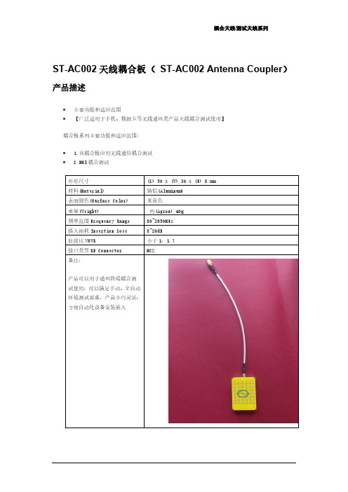

HG-AF03双频GNSS射频模块产品说明书V1.0 (支持任意两个GNSS频点,支持模拟中频输出或数字中频输出)北京星源北斗导航技术有限责任公司2019 年 12 月10 日更多详细信息请致电星源北斗咨询!公司地址:北京市海淀区温泉镇显龙山路19号北辰香麓雅庭A座218室电话:136****9930传真:************QQ:5024141邮箱:***************1 产品概述表1 产品价格表图1 HG-AF03双频GNSS 射频模块双频GNSS射频模块(HG-AF03)主要用于双模融合联合定位、双频差分定位等场合,支持差分模拟中频输出,也可支持中频数字信号输出(不推荐,主要原因是IPX 头不方便直连FPGA),每个射频支持两个独立的射频输入,分别对应L1附近的频点和L2/L5/B3附近的频点,提供3.3V馈电,射频输入加入的阻抗匹配可接信号模拟器、多频天线。
HG-AF03由2个独立的MAX2771射频芯片组成,2个射频芯片时钟同源。
2个MAX2771可以独立配置(基于3针RS232串口线),可支持I路和Q路信号同时输出。
2 主要参数HG-AF03基本特性如下:1.射频芯片:MAX2771×3,可支持任意GNSS频点,比如L1/L2/L5, B1c/ B1I/B2a/B3I。
2.TCXO:16.369MHz。
3.射频接口:IPX×4,提供3.3V天线馈电,其中HI口表示L1附近频点输入,LO口表示L2/L5/B3附近频点输入,每个射频HI口和LO口同时只能有一个接天线。
4.中频接口:⚫I/Q支路差分模拟输出,每对差分信号各2个IPX头。
⚫1个GPSCLK时钟输出,IPX接口。
⚫1个CLKIN输入口。
⚫各MAX272771的SPI接口连接板子上的STM32处理器上,通过串口设置STM32处理器存储的配置参数。
⚫需要外部提供+5V供电或者MicroUSB供电。

•Wireless application – ISM band, including WiFi / Bluetooth •High density applications•Bluetooth headsets or ear pieces •Computer mouse and keyboards •PROFINET – Industrial automation •Video Game systems•Alternative to larger PCB solutionFEATURES:APPLICATIONS:•2470MHz, Bandwidth ≥200MHz •Suitable for RoHS compliant reflow •Gain 2.6dBi (Peak) / 0.7dBi (Average)•VSWR <2:1•Small size – 7.0 x 2.0 x 1.0mm (0.275 x 0.078 x 0.039inch)•Non Ground Mounting type.•Power Handling 3W Max •Matched to 50 OhmSTANDARD SPECIFICATIONSMaximum RatingsElectrical Characteristics5101 Hidden Creek Lane Spicewood TX 78669Phone: 512-371-6159 | Fax: 512-351-8858For terms and conditions of sale visit:ABRACON IS ISO9001-2008CERTIFIEDREVISED: 05.17.2017OUTLINE DIMENSIONS:REFLOW PROFILE:(Dimensions: mm)Recommended Land Pattern•Preheat condition: 150 ~200 /60~120ºC sec .•Allo w ed time above 217ºC: 60~90sec . •Ma x temp: 260ºC•Ma x time at ma x temp: 10sec .•Solder paste: Sn/3.0Ag/0.5Cu •Allo w ed Re f lo w time: 2x ma x[Note: The re f lo w pro f ile in the above table is only f or quali f ication and is not meant to speci f y board assembly pro f iles . Actual board assembly pro f iles must be based on the customer 's speci f ic board design, solder paste and process, and should not e x ceed the parameters as the Re f lo w pro f ile sho w s .]Pre -heating Temperature: 120ºC, 60 ºC ~ 300 sec .•Iron soldering po w er: Ma x.30W .•Pre -heating: 150 / 60 sec. ºC .•Soldering Tip temperature: 350 Ma x. ºC .•Soldering time: 3 sec Ma x.•Solder paste: Sn/3.0Ag/0.5Cu .•Ma x 1 times f or iron soldering .•Soldering Temperature: 340ºC ±5ºC, 5sec ma x per each terminal .[Note: Take care not to apply the tip o f the soldering iron to the terminal electrodes.]MANUAL SOLDERINGSeries A B C D E F G 5101 Hidden Creek Lane Spicewood TX 78669Phone: 512-371-6159 | Fax: 512-351-8858For terms and conditions of sale visit:ABRACON IS ISO9001-2008CERTIFIEDREVISED: 05.17.2017s products are COTS – Commercial-O ff-The-Shel f products ; suitable for Commercial, Industrial and, ically designed for Military, Aviation, Aerospace, Li f e-dependant Medical applications or any application requiring high reliability e and/or property . For applications requiring high reliability and/or presenting an e authorization from Abracon Corporation is required. Please contact Abracon Corporation for more information .Note: The sprocket holes are to the right as the tape is pulled to w ard the user Mounting Direction of Tape on ReelW 16.0±0.10 D01.50 +0.10 / -0.0P1 8.0±0.10 P0 4.0±0.10 E 1.75±0.10 K0 1.40±0.10 F 7.50±0.15 A0 2.30±0.10 5101 Hidden Creek Lane Spicewood TX 78669。

BOOMSENSE天线产品使用手册版本号:V1.0(仅供内部使用For internal use only)编制:万文定职位:技术部经理日期:2006-6-13审核:张金木职位:物流部经理日期:目录Table of Contents一、室内全向吸顶天线 (4)二、室内定向吸顶天线 (6)三、室内定向壁挂天线 (9)四、八木定向天线 (11)五、对数周期天线 (20)六、角反射天线 (22)七、抛物面天线 (24)八、栅网抛物面天线 (31)九、背射定向天线 (34)十、全向天线 (37)十一、平板定向天线(定向板状天线) (45)十二、鞭状天线 (71)十三、隐蔽美化天线 (72)天线产品命名规则:型号组成:BS - X0X1 - X2X3X4/X5X6/ X7X8- X9X10 / X11X12- X13X14规格代码:表示天线版本、倾角、接头类型、适用范围等信息。
BS:邦讯公司产品缩写代码X0X1 :天线类型1、XD:室内吸顶天线2、BG:室内壁挂天线3、BM:八木天线4、DS:对数周期天线5、PW:抛物面天线6、BS:背射天线7、BZ:鞭状天线8、GS:室外全向天线9、PB:室外定向板状天线10、FS:角反射天线11、YB:美化隐蔽天线X2 X3X4:H面方向角如:360◦表示为360 65◦表示为65 90◦表示为90 120◦表示为120X5 X6:增益(双频天线以低频段增益为标示,单位:dBi)如:11.0 dBi表示为11,11.1~12 dBi表示为12X7 X8:内置下倾角如:10◦表示为10 15◦表示为15 20◦表示为20X9 X10/ X11X12:工作频带(单位:MHz)如:08/09表示为806~960 MHz (适合GSM&CDMA系统)08/2.5表示为806~2500 MHz(适合GSM&CDMA&SCDMA&DCS&PHS&3G&WLAN等系统)X13:极化方式如:V表示为垂直极化R表示为±45o双极化C表示为圆极化X14:功率容量如:B表示为大功率容量(即≥250W)一、室内全向吸顶天线Indoor Ceiling AntennaBS-XD-360/02-08/09V BS-XD-360/03-08/2.5V BS-XD-360/03-08/2.5V-DBS-XD-360/04-1.7/2.5V二、室内定向吸顶天线Indoor directional Ceiling AntennaBS-XD-100/07-0.8/2.5VBS-XD-115/05-08/2.5VBS-XD-95/06-08/2.5V三、室内定向壁挂天线Indoor Wall-mounting AntennaBS-BG-90/08-08/2.5VBS-BG-75/09-08/2.5VB四、八木定向天线Yagi Directional AntennaBS-BM-60/9-04VBS-BM-30/12-07/08VBS-BM-36/12-06/07VBS-BM-40/12-1.1/1.4VBS-BM-38/12-1.4/1.5VBS-BM-38/12-1.8/1.9VBS-BM-38/12-1.9/2.1VBS-BM-40/12-2.4V五、对数周期天线Logarithm Week Directional AntennaBS-DS-90/09-08/2.5VBS-DS-65/11-08/2.5V六、角反射天线Angle Mix Corner Reflector Directional AntennaBS-FS-33/16-08/09V七、抛物面天线Angle Mix Corner Reflector Directional AntennaBS-PW-19/17-04VBS-PW-11/21-07/08V八、栅网抛物面天线Grid Parabolic AntennaBS-PW-9/24-2.4VBS-PW-5/31-2.5/2.6VBS-PW-6/28-5.7/5.8V九、背射定向天线 Backfire Directional Antenna十、全向天线Omni-directional AntennaBS-GS-360/11-1.9/2.1VBS-GS-360/11-2.4VBS-GS-360/11-3.4/3.6VBS-GS-360/11-5.7/5.8V十一、平板定向天线(定向板状天线) Panel Directional AntennaBS-PB-65/14-04VBS-PB-65/17-07/08V。
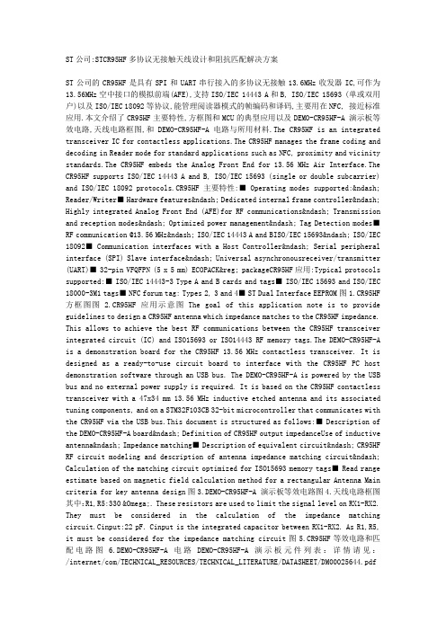
ST公司:STCR95HF多协议无接触天线设计和阻抗匹配解决方案ST公司的CR95HF是具有SPI和UART串行接入的多协议无接触13.6MHz收发器IC,可作为13.56MHz空中接口的模拟前端(AFE),支持ISO/IEC 14443 A和B, ISO/IEC 15693 (单或双用户)以及ISO/IEC 18092等协议,能管理阅读器模式的帧编码和译码,主要用在NFC, 接近标准应用.本文介绍了CR95HF主要特性,方框图和MCU的典型应用以及DEMO-CR95HF-A 演示板等效电路,天线电路框图,和DEMO-CR95HF-A电路与所用材料.The CR95HF is an integrated transceiver IC for contactless applications.The CR95HF manages the frame coding and decoding in Reader mode for standard applications such as NFC, proximity and vicinity standards.The CR95HF embeds the Analog Front End for 13.56 MHz Air Interface.The CR95HF supports ISO/IEC 14443 A and B, ISO/IEC 15693 (single or double subcarrier) and ISO/IEC 18092 protocols.CR95HF主要特性:■ Operating modes supported:– Reader/Writer■ Hardware features– Dedicated internal frame controller– Highly integrated Analog Front End (AFE)for RF communications– Transmission and reception modes– Optimized power management– Tag Detection modes■ RF communication @13.56 MHz– ISO/IEC 14443 A and BISO/IEC 15693– ISO/IEC 18092■ Communication interfaces with a Host Controller– Serial peripheral interface (SPI) Slave interface– Universal asynchronousreceiver/transmitter (UART)■ 32-pin VFQFPN (5 x 5 mm) ECOPACK® packageCR95HF应用:Typical protocols supported:■ ISO/IEC 14443-3 Type A and B cards and tags■ ISO/IEC 15693 and ISO/IEC 18000-3M1 tags■ NFC forum tag: Types 2, 3 and 4■ ST Dual Interface EEPROM图1.CR95HF 方框图图 2.CR95HF应用示意图The goal of this application note is to provide guidelines to design a CR95HF antenna which impedance matches to the CR95HF impedance. This allows to achieve the best RF communications between the CR95HF transceiver integrated circuit (IC) and ISO15693 or ISO14443 RF memory tags.The DEMO-CR95HF-A is a demonstration board for the CR95HF 13.56 MHz contactless transceiver. It is designed as a ready-to-use circuit board to interface with the CR95HF PC host demonstration software through an USB bus. The DEMO-CR95HF-A is powered by the USB bus and no external power supply is required. It is based on the CR95HF contactless transceiver with a 47x34 mm 13.56 MHz inductive etched antenna and its associated tuning components, and on a STM32F103CB 32-bit microcontroller that communicates with the CR95HF via the USB bus.This docum ent is structured as follows:■ Description of the DEMO-CR95HF-A board– Definition of CR95HF output impedanceUse of inductive antenna– Impedance matching■ Description of equivalent circuit– CR95HF RF circuit modeling and description of antenna impedance matching circuit– Calculation of the matching circuit optimized for ISO15693 memory tags■ Read range estimate based on magnetic field calculation method for a rectangular Antenna Main criteria for key antenna design图3.DEMO-CR95HF-A 演示板等效电路图4.天线电路框图其中:R1,R5:330 Ω. These resistors are used to limit the signal level on RX1-RX2. They must be considered in the calculation of the impedance matching circuit.Cinput:22 pF. Cinput is the integrated capacitor between RX1-RX2. As R1,R5, it must be considered for the impedance matching circuit图5.CR95HF等效电路和匹配电路图 6.DEMO-CR95HF-A电路DEMO-CR95HF-A 演示板元件列表:详情请见:/internet/com/TECHNICAL_RESOURCES/TECHNICAL_LITERATURE/DATASHEET/DM00025644.pdf和/internet/com/TECHNICAL_RESOURCES/TECHNICAL_LITERATURE/APPLICATION_NOTE/DM000271 98.pdf。

6-port sector antenna, 2x 698–960 and 4x 1710–2690 MHz, 65°HPBW, 3x RET with manual override.Integrated Internal Remote Electrical Tilt (RET), with independent control of electrical tilt withmanual override on all arraysOBSOLETEThis product was discontinued on: March 27, 2020General SpecificationsAntenna Type SectorBand MultibandGrounding Type RF connector inner conductor and body grounded to reflector andmounting bracketPerformance Note Outdoor usageRadome Material ASA, UV stabilizedRF Connector Interface7-16 DIN FemaleRF Connector Location BottomRF Connector Quantity, high band4RF Connector Quantity, low band2RF Connector Quantity, total6Remote Electrical Tilt (RET) InformationRET Interface8-pin DIN Female | 8-pin DIN MaleRET Interface, quantity 3 female | 3 maleInput Voltage10–30 VdcInternal RET High band (2) | Low band (1)Power Consumption, idle state, maximum 2 WPower Consumption, normal conditions, maximum13 WProtocol3GPP/AISG 2.0 (Single RET)DimensionsWidth353 mm | 13.898 in16Page ofPage of 26Depth 209 mm | 8.228 in Length1380 mm | 54.331 in Net Weight, without mounting kit20 kg | 44.092 lbArray LayoutElectrical SpecificationsImpedance50 ohmOperating Frequency Band 1710 – 2690 MHz | 698 – 960 MHz Polarization±45°Electrical SpecificationsFrequency Band, MHz698–790790–890890–9601710–19201920–21702300–2690 Gain, dBi13.413.714.216.617.117.8 Beamwidth, Horizontal,degrees67.768.762.66263.161 Beamwidth, Vertical, degrees20.218.116.68.37.36Beam Tilt, degrees0–100–100–100–100–100–10 USLS (First Lobe), dB181818181818Null Fill, dB-22-22-22Front-to-Back Ratio at 180°,dB252323283230CPR at Boresight, dB171313191716CPR at Sector, dB10109755 Isolation, Cross Polarization,dB252525252525 Isolation, Inter-band, dB283030272830VSWR | Return loss, dB 1.43 | 15.0 1.43 | 15.0 1.43 | 15.0 1.5 | 14.0 1.5 | 14.0 1.5 | 14.0 PIM, 3rd Order, 2 x 20 W, dBc-150-150-150-150-150-150Input Power per Port,maximum, watts300300300250250250 Electrical Specifications, BASTAFrequency Band, MHz698–790790–890890–9601710–19201920–21702300–2690 Gain by all Beam Tilts,average, dBi13.213.51416.316.817.4Gain by all Beam TiltsTolerance, dB±0.2±0.2±0.3±0.5±0.4±0.6Gain by Beam Tilt, average, dBi 0 ° | 13.35 ° | 13.210 ° | 13.20 ° | 13.55 ° | 13.510 ° | 13.40 ° | 14.05 ° | 14.110 ° | 14.00 ° | 16.45 ° | 16.310 ° | 16.30 ° | 16.85 ° | 16.810 ° | 16.90 ° | 17.65 ° | 17.510 ° | 17.1Beamwidth, HorizontalTolerance, degrees±1.6±1.8±2.1±2.9±5±6.5Beamwidth, VerticalTolerance, degrees±0.9±1.1±0.8±0.6±0.6±0.5USLS, beampeak to 20° abovebeampeak, dB181818181818Front-to-Back Total Power at180° ± 30°, dB242223232526CPR at Boresight, dB181314211818CPR at Sector, dB11108754Page of36Mechanical SpecificationsWind Loading @ Velocity, frontal575.0 N @ 150 km/h (129.3 lbf @ 150 km/h) Wind Loading @ Velocity, lateral220.0 N @ 150 km/h (49.5 lbf @ 150 km/h) Wind Loading @ Velocity, rear590.0 N @ 150 km/h (132.6 lbf @ 150 km/h) Wind Speed, maximum250 km/h (155 mph)Packaging and WeightsWidth, packed420 mm | 16.535 inDepth, packed320 mm | 12.598 inLength, packed1560 mm | 61.417 inWeight, gross36 kg | 79.366 lbRegulatory Compliance/CertificationsAgency ClassificationCE Compliant with the relevant CE product directivesCHINA-ROHS Above maximum concentration valueISO 9001:2015Designed, manufactured and/or distributed under this quality management system REACH-SVHC Compliant as per SVHC revision on /ProductCompliance ROHS Compliant/ExemptedUK-ROHSCompliant/ExemptedIncluded ProductsT-041-GL-E–Adjustable Tilt Pipe Mounting Kit for 2.0"-4.5" (60-115mm) OD round members for panelantennas. Includes 2 clamp sets.* FootnotesPerformance Note Severe environmental conditions may degrade optimum performancePage of46Adjustable Tilt Pipe Mounting Kit for 2.0"-4.5" (60-115mm) OD roundmembers for panel antennas. Includes 2 clamp sets.Product ClassificationProduct Type Adjustable tilt mounting kitGeneral SpecificationsApplication OutdoorColor SilverDimensionsCompatible Length, maximum1500 mm | 59.055 inCompatible Length, minimum1200 mm | 47.244 inCompatible Diameter, maximum115 mm | 4.528 inCompatible Diameter, minimum60 mm | 2.362 inAntenna-to-Pipe Distance85 mm | 3.346 inBracket-to-Bracket Distance976 mm | 38.425 inWeight, net 5.5 kg | 12.125 lbMaterial SpecificationsMaterial Type Galvanized steelMechanical SpecificationsMechanical Tilt0°–12° in steps of 2°Packaging and WeightsIncluded Brackets | HardwarePackaging quantity1Regulatory Compliance/CertificationsAgency ClassificationCE Compliant with the relevant CE product directives56Page ofCHINA-ROHS Below maximum concentration valueISO 9001:2015Designed, manufactured and/or distributed under this quality management system REACH-SVHC Compliant as per SVHC revision on /ProductCompliance ROHS CompliantUK-ROHSCompliantPage of66。
东三通信天线(结构)研制
宋剑鸣
【期刊名称】《空间电子技术》
【年(卷),期】1994(000)003
【摘要】东三通信天线是我所与德国MBB公司合作研制的、处于国际先进水平的天线分系统。
天线电设计采用了频率复用及赋形波束技术,在结构上采用了极化敏感反射器、两套多喇叭馈源、电动展开机构、全部复合材料蜂窝结构设计等先进技术。
天线重量轻,刚度好,展开重复精度高。
在设计中进行了结构分析、热分析等严格的分析计算工作,对产品进行了一系列的测试试验。
文中对设计、试验、分析等进行了简略的介绍。
【总页数】6页(P61-66)
【作者】宋剑鸣
【作者单位】无
【正文语种】中文
【中图分类】V474.21
【相关文献】
1.美军先进通信天线的研制情况 [J], 张涛
2.基于GTD的散射通信天线分析与研制 [J], 李中;张晨新;盛川
3.车载卫星通信天线自动控制系统的研制 [J], 汤军;陶娅;杨书奎
4.美国先进军用通信天线的研制情况 [J], 谢海
5.扇三角洲不同粒级砂岩储层微观孔隙结构定量表征:以石臼坨凸起陡坡带东三段为例 [J], 万琳;王清斌;赵国祥;汤国民;高曦龙
因版权原因,仅展示原文概要,查看原文内容请购买。
宽带超低副瓣天线阵设计
孙绍国;张玉梅;卢晓鹏;冯祖建
【期刊名称】《电讯技术》
【年(卷),期】2006(046)003
【摘要】描述了由16元线阵组成的L频段宽带超低副瓣天线阵的设计,给出了设计过程中所解决的各项关键技术及所采用的技术途径,以及一些设计数据和测试结果.天线近场测试表明,所研制的天线在优于25%频带内天线峰值副瓣电平低于-38 dB,垂直面扫描±30°时,天线峰值副瓣电平低于-35 dB.
【总页数】6页(P87-92)
【作者】孙绍国;张玉梅;卢晓鹏;冯祖建
【作者单位】华东电子工程研究所,合肥,230031;华东电子工程研究所,合
肥,230031;华东电子工程研究所,合肥,230031;华东电子工程研究所,合肥,230031【正文语种】中文
【中图分类】TN82
【相关文献】
1.64元宽带高增益低副瓣毫米波天线阵的设计 [J], 吕芳;刘景萍
2.高增益低副瓣X波段宽带圆极化Vivaldi天线阵设计 [J], 吴文鹤;韦高;赵文奇;李文廷
3.L波段宽带超低副瓣波导缝隙阵列天线设计 [J], 陈良圣
4.混沌免疫算法应用于超低副瓣天线阵优化研究 [J], 蔡木仁;刘波
5.宽带阵列超低副瓣实现技术 [J], 黄华;于勇
因版权原因,仅展示原文概要,查看原文内容请购买。