NETGEAR 7000 可网管交换机说明文档
- 格式:pdf
- 大小:1.80 MB
- 文档页数:94
NETGEAR7000交换机组播路由DVMRP一、DVMRP概述组播的路由:具有组播能力的网络由支持本地组播的局域网通过具有组播能力的路由器连接而成。
IP组播路由的关键是为每一个组播组建立组播的分配树,当组播的分配树建立好时,每个组播路由器只要将该组的数据沿着分配树进行传播就可以了。
组播路由协议:第一类是建立在组播组成员在网络上的分布比较密集并且带宽比较充足的基础上的。
此种模式称为密集模式。
密集模式组播路由协议包括距离向量组播路由协议(Distance Vector Multicast Routing Protocol, DVMRP),组播开放最短路径优先协议(Multicast Open Shortest Path First, MOSPF),密集模式独立组播协议(Protocol-independent Multicast-Dense Mode, PIM-DM)。
距离矢量组播路由选择协议(DVMRP:Distance Vector Multicast Routing Protocol)是一种互联网路由协议,为互联网络的主机组提供了一种面向无连接信息组播的有效机制。
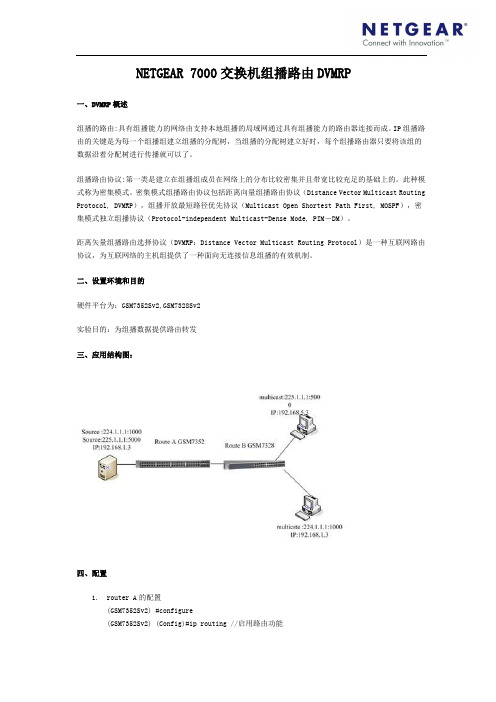
二、设置环境和目的硬件平台为:GSM7352Sv2,GSM7328Sv2实验目的:为组播数据提供路由转发三、应用结构图:四、配置1.router A的配置(GSM7352Sv2) #configure(GSM7352Sv2) (Config)#ip routing //启用路由功能(GSM7352Sv2) (Config)# ip multicast//启用去组播功能(GSM7352Sv2) (Config)# ipdvmrp//启用组播路由DVMRP(GSM7352Sv2) (Config)#interface 1/0/2(GSM7352Sv2) (Interface 1/0/2)#ip address 192.168.2.1 255.255.255.0//为接口配置ip地址(GSM7352Sv2) (Interface 1/0/2)#routing//使接口成为三层路由接口(GSM7352Sv2) (Interface 1/0/2)# ipdvmrp//该接口启用DVMRP(GSM7352Sv2) (Interface 1/0/2)#exit(GSM7352Sv2) (Config)#interface vlan 1(GSM7352Sv2) (Interface-vlan 1)# ip address 192.168.1.1 255.255.255.0 //为vlan1配置ip地址(GSM7352Sv2) (Interface-vlan1)#ip routing//开启vlan路由(GSM7352Sv2) (Interface-vlan 1)#ipdvmrp//该接口启用DVMRP(GSM7352Sv2) (Interface-vlan 1)#exit2.router B的配置(GSM7328Sv2) #configure(GSM7328Sv2) (Config)#ip routing(GSM7328Sv2) (Config)# ip multicast(GSM7328Sv2) (Config)# ipdvmrp(GSM7328Sv2) (Config)#ipigmp//使能全局igmp(GSM7328Sv2) (Config)#interface 1/0/2(GSM7328Sv2) (Interface 1/0/2)#ip address 192.168.2.2 255.255.255.0(GSM7328Sv2) (Interface 1/0/2)#routing(GSM7328Sv2) (Interface 1/0/2)# ipdvmrp(GSM7328Sv2) (Interface 1/0/2)#exit(GSM7328Sv2) (Config)#interface vlan 1(GSM7328Sv2) (Interface-vlan 1)# ip address 192.168.3.1 255.255.255.0(GSM7328Sv2) (Interface-vlan1)#ip routing(GSM7328Sv2) (Interface-vlan 1)#ipdvmrp(GSM7328Sv2) (Interface-vlan 1)#ipigmp//使能vlan1的igmp,vlan1下有要接受组播数据的成员(GSM7328Sv2) (Interface-vlan 1)#exit(GSM7328Sv2) #vlandatabase(GSM7328Sv2) (Vlan)#vlan2//创建vlan2(GSM7328Sv2) (Vlan)#exit(GSM7328Sv2)#conf(GSM7328Sv2) (Config)# conf-if-range-1/0/22-1/0/25(GSM7328Sv2) (conf-if-range-1/0/22-1/0/25)#vlan participation include 2//把接口22,23,24,25定义为vlan2的成员(GSM7328Sv2) (conf-if-range-1/0/22-1/0/25)#vlanpvid 2//修改这几个端口的PVID值(GSM7328Sv2) (Interface-vlan 2)# ip address 192.168.5.1 255.255.0.0 //配置vlan2的ip 地址(GSM7328Sv2) (Interface-vlan 2)#ip routing(GSM7328Sv2) (Interface-vlan 2)#exit-------vlan2下没有要接受组播数据的成员,因此不需开启dvmrp和igmp五、测试结果1. router A,为有接受组播数据的接口outgoing转发数据1. router B为有接受组播数据的接口outgoing转发数据,没接受成员的接口没数据转发2. 把组播成员退出组播组,发现路由器没有outging 的接口转发组播数据。

1instructions.computers.T ap the Security icon in your Check out everything you can do on the Nighthawk app! Pause the Internet, run a speed test, set smart parental controls, and more.2Secure your 3Do more with theappContents OverviewTroubleshootingSi ce produit est vendu au Canada, vous pouvez accéder à ce document en français canadien à https:///support/download/.(If this product is sold in Canada, you can access this document in Canadian French at https:///support/download/.)For regulatory compliance information including the EU Declaration of Conformity, visit https:///about/regulatory/.See the regulatory compliance document before connecting the power supply.For NETGEAR’s Privacy Policy, visit https:///about/privacy-policy.By using this device, you are agreeing to NETGEAR’s T erms and Conditions athttps:///about/terms-and-conditions. If you do not agree, return the device to your place of purchase within your return period.Applicable to 6 GHz devices only: Only use the device indoors. The operation of 6 GHz devices is prohibited on oil platforms, cars, trains, boats, and aircraft, except that operation of this device is permitted in large aircraft while flying above 10,000 feet. Operation of transmitters in the 5.925-7.125 GHz band is prohibited for control of or communications with unmanned aircraft systems.NETGEAR, Inc.350 East Plumeria Drive San Jose, CA 95134, USA© NETGEAR, Inc., NETGEAR and the NETGEAR Logo are trademarks of NETGEAR, Inc. Any non-NETGEAR trademarks are used for reference purposes only.NETGEAR INTERNATIONAL LTD Floor 1, Building 3,University Technology Centre Curraheen Road, Cork, T12EF21, IrelandMay 2022RouterEthernet cablePower adapter(varies by region)Power LED Ethernet LAN Ports 1–5 LEDs A WiFi On/Off button with LED FMulti-Gig Internet port/Ethernet LAN port 5Internet LED USB 3.0 LEDB WPS button with LED GUSB 3.0 port 2.4 GHz WiFi LED C Reset button HPower On/Off button 5 GHz WiFi LED D 1G Internet port/Ethernet LAN port 5IPower connector6 GHz WiFi LEDEEthernet LAN ports 1–4If you’re having problems with the installation, try the following:•Turn off your modem and router and disconnect them. Restart yourmodem. Reconnect your router to your modem, and try installing with the Nighthawk app again.• If you’re still unable to install your router using the Nighthawk app,manually install it using the router web interface.Visit to access the router web interface.If you already own another NETGEAR router and you used the Nighthawk app before, go to the dashboard and tap > NEW SETUP to install your new router.For more information, visit /routerhelp.Visit /support to get your questions answered and access the latest downloads.You can also check out our NETGEAR Community for helpful advice at .Support and CommunityRegulatory and LegalNOTE: You can use either the 1G Internet port or Multi-Gig Internet port to connect to the Internet.。
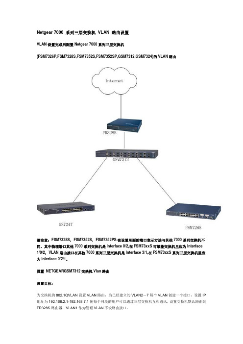
Netgear 7000 系列三层交换机VLAN 路由设置VLAN设置完成后配置Netgear 7000系列三层交换机(FSM7326P,FSM7328S,FSM7352S,FSM7352SP,GSM7312,GSM7324)的VLAN路由请注意:FSM7328S,FSM7352S,FSM7352PS在设置里面的端口表示方法与其他7000系列交换机不同,其中物理端口其他7000系列交换机是Interface 0/2,在FSM73xxS可堆叠交换机里应为Interface 1/0/2;VLAN路由接口在其他7000系列三层交换机是Interface 3/1,在FSM73xxS系列三层交换机里应为Interface 0/2/1。
设置NETGEARGSM7312交换机Vlan路由设置目标:为交换机的802.1QVLAN设置VLAN路由,为已经建立的VLAN2-7每个VLAN创建一个接口,设置IP 地址为192.168.2.1-192.168.7.1使每个网段的用户可以通过三层交换机互相通讯,设置交换机默认路由到FR328S路由器,VLAN1作为管理VLAN不设路由接口。
配置步骤:∙使用9针串口设置线连接GSM7312交换机,进入CLI配置界面,使用(GSM7312)# Clear Config 命令恢复出厂设置。
∙然后使用命令(GSM7312)#Reload ; 系统提示是否保存现有配置(选择YES)。
然后系统重新启动。
∙配置GSM7312交换机管理IP地址为192.168.0.238/24,配置完毕后保存。
∙连接配置计算机的网线到GSM7312的端口10;∙打开IE浏览器,在URL处输入http://192.168.0.238/,进入交换机配置管理界面。
∙配置交换机的VLAN,请参考Netgear 7000系列交换机VLAN设置。
∙在交换机左边选择Routing>VLAN Routing>Config页面创建VLAN2的路由接口:在VLAN ID栏填入2,然后点击Create 创建。

NETGEAR 交换机的基本管理和端口配置1.实验目的本实验将详细描述Netgear系列交换机常用的基本管理特性的操作和端口配置的方法,主要包括以下内容:1.配置交换机的管理IP地址2.配置交换机的固件升级3.配置交换机的基本端口设置通过以上实验操作,实验者可以学会独立安装及交换机基本设置的能力,并能应用于实际网络环境下,另外,如果你不了解交换机基本的设置,那么将无法实现对交换机做全面和深入的配置,尽管这节内容很简单,但也是最基本和必须掌握的内容。
1.1实验条件要完成实验内容,必须具备以下环境.1.NETGEAR 7000系列交换机(以GSM7328S为例,固件版本7.1.1.7)一台2.NETGEAR增强型智能网管交换机(以GS724AT为例,固件版本3.0.61)一台3.NETGEAR基本智能交换机(以FS726T为例,固件版本1.2.4_35)一台4.NETGEAR智能交换机配置向导软件(SmartWizard_2.05.05)5.NETGEAR简单网管交换机(以JFS524E,GS105E为例)两台6.NETGEAR简单网管交换机管理工具(NETGEAR UM+ Utility V1.2B20)7.TFTP Server软件8.NETGEAR7000系列交换机随机9针串口设置电缆一根,网线数条(正线若干根)9.测试用的个人电脑若干注:如果需要获得NETGEAR公司所有产品的最新软件,请平常及时访问,并请注意每个产品升级的注意事项。
2.实验内容2.1配置交换机的管理IP地址2.1.1规划内部网络的IP在配置交换机的管理IP地址之前,我们应该先根据企业使用的实际情况,预先规划及确定企业内部网络的IP地址,依据因特网域名分配组织IANA组织(Internet Assigned Numbers Authority)规划保留了以下三个IP地址块用于私有网络的使用:10.0.0.0 - 10.255.255.255 (10/8比特前缀)172.16.0.0 - 172.31.255.255 (172.16/12比特前缀)192.168.0.0 - 192.168.255.255 (192.168/16比特前缀)NETGEAR系列交换机缺省的设备管理IP局域网地址分为以下几种类型:7000系列交换机:169.254.100.100 / 255.255.0.0;可以通过DHCP服务器动态分配获得IP地址。

一、802.1x端口认证原理为什么需要IEEE802.1x?随着宽带以太网建设规模的迅速扩大,网络上原有的认证系统已经不能很好地适应用户数量急剧增加和宽带业务多样性的要求。
IEEE802.1x协议具有完备的用户认证、管理功能,可以很好地支撑宽带网络的计费、安全、运营和管理要求,对宽带IP城域网等电信级网络的运营和管理具有极大的优势。
IEEE802.1x协议对认证方式和认证体系结构上进行了优化,解决了传统PPPOE和WEB/PORTAL 认证方式带来的瓶颈问题,更加适合在宽带以太网中的使用。
IEEE802.1x是IEEE在2001年6月通过的基于端口访问控制的接入管理协议标。
IEEE802系列LAN标准是目前居于主导地位的局域网络标准,传统的IEEE802协议定义的局域网不提供接入认证,只要用户能接入局域网控制设备,如传统的LanSwitch,用户就可以访问局域网中的设备或资源,这是一个安全隐患。
对于移动办公,驻地网运营等应用,设备提供者希望能对用户的接入进行控制和配置,此外还存在计费的需求。
因此,802.1x产生了。
IEEE802.1x是一种基于端口的网络接入控制技术,在LAN 设备的物理接入级对接入设备进行认证和控制,此处的物理接入级指的是LanSwitch设备的端口。
连接在该类端口上的用户设备如果能通过认证,就可以访问LAN 内的资源;如果不能通过认证,则无法访问LAN 内的资源,相当于物理上断开连接。
下面首先让我们了解一下IEEE802.1x端口访问控制协议的体系结构。
1. IEEE802.1x 体系介绍虽然IEEE802.1x定义了基于端口的网络接入控制协议,但是需要注意的是该协议仅适用于接入设备与接入端口间点到点的连接方式,其中端口可以是物理端口,也可以是逻辑端口。
典型的应用方式有:LanSwitch 的一个物理端口仅连接一个End Station,这是基于物理端口的;IEEE 802.11定义的无线LAN 接入方式是基于逻辑端口的。

注:产品外观因型号而异。
第 2 步:连接到电源并开机。
第 1步:连接设备。
注:电源适配器因地区而异。
计算机因特网第 3 步:检查状态。
电源 LED端口 LED通电以太网连接未通电活动(闪烁)无连接(熄灭)技术支持感谢您购买此 NETGEAR 设备。
安装设备后,请找到产品标签上的序列号并使用它在https://上注册产品。
只有在注册产品后,才能使用 NETGEAR 电话支持。
NETGEAR 建议通过 NETGEAR网站注册产品。
如需产品更新和网络支持,请访问 。
NETGEAR 建议您只使用 NETGEAR 官方支持资源。
您可以在以下网站上找到多种语言的安装指南: 。
有关产品规格的信息,请参阅产品页面或通过以下网站下载数据表: 。
如需最新的欧盟符合性声明,请访问/app/answers/detail/a_id/11621/ 。
有关法规遵从性信息,请访问/about/regulatory/ 。
连接电源之前,请查阅合规性文件。
警告:出于安全考虑,务必仅使用随附产品销售的电源适配器。
如果您不确定要使用哪种电源适配器,请与 NETGEAR 技术支持联系。
支持热线:4008303815中文技术支持站点:网件社区:技术规格百兆和千兆非网管交换机200 和 300 系列200 系列:• 8 口千兆交换机 GS208300 系列:• 8 口百兆交换机 FS308• 8 口千兆交换机 GS3082016 年 7 月有限保修产品注册感谢您选择NETGEAR产品。
如果您想注册您的产品、获取免费支持期(可以于购买产品后的 90 天内通过电话获得基础技术支持)以及查看通用的产品信息和文档,请浏览:https:///registration/login.aspx敬请保管好您产品的有效购买凭证。
本保修声明涵盖的产品NETGEAR 通过本保修声明赋予消费者的权益是对消费者在与商品和服务保修相关的中国法律项下所享有的权利和救济的补充(如果其范围超过消费者在中国法律项下的权利和救济)。
在 NETGEAR 7000 系列交换机的端口上绑定 MAC 和 IP 地址1.基于端口的MAC地址绑定NETGEAR FSM7352S交换机为例,登录进入交换机,输入管理口令进入配置模式,敲入命令:(FSM7352S) #configure//进入配置模式(FSM7352S) (Config)#port-security//打开端口安全模式(FSM7352S) (Config)#interface 1/0/45//进入具体端口配置模式(FSM7352S) (Interface 1/0/45)#port-security//配置端口安全模式(FSM7352S) (Interface 1/0/45)#port-security mac-address 00:E0:4C:00:0C:2B 1//配置该端口要绑定的主机的MAC地址和所属VLAN(FSM7352S) (Interface 1/0/45)#port-security max-dynamic 0//配置该端口动态学习MAC地址数量为0,即不再学习动态MAC地址(FSM7352S) (Interface 1/0/45)#port-security max-static 1//配置该端口静态MAC地址数量为1,即不能再添加静态MAC地址以上命令设置交换机上某个端口绑定一个具体的MAC地址,这样只有这个主机可以通过这个端口使用网络,并且该主机只能通过这个端口使用网络。
如果对该主机的网卡进行了更换或者其他PC机想通过这个端口使用网络都不可用,除非删除或修改该端口上绑定的MAC地址,才能正常使用。
注意:以上功能适用于FSM7328S,FSM7352S,FSM7352PS,GSM7324,GSM7312,GSM7212,GSM7224,GSM7248,FSM7326P系列交换机4.0以上软件版本。
2.基于MAC地址的扩展访问列表(FSM7352S) (Config)#mac access-list extended testmac01//定义一个MAC地址访问控制列表并且命名该列表名为testmac01(FSM7352S) (Config-mac-access-list)#permit 00:E0:4C:00:0C:2B any//定义MAC地址为00:E0:4C:00:0C:2B的主机可以访问任意主机(FSM7352S) (Config-mac-access-list)#permit any 00:E0:4C:00:0C:2B//定义所有主机可以访问MAC地址为00:E0:4C:00:0C:2B的主机(FSM7352S) (Config)#interface 1/0/45//进入具体端口的配置模式(FSM7352S) (Interface 1/0/45)#mac access-group testmac01 in//在该端口上应用名为testmac01的访问列表(即前面我们定义的访问策略)此功能与1大体相同,但它是基于端口做的MAC地址访问控制列表限制,可以限定特定源MAC地址与目的地址范围。
《简单网管交换机VLAN功能设置—中文版》作者Author:Kim美国网件中国客户服务部NETGEAR China Customer Services Department网件社区互动:技术支持电话:400 830 3815技术支持邮箱:****************.cnVLAN(Virtual Local Area Network)的中文名为虚拟局域网。
VLAN是一种将局域网设备从逻辑上划分成多个网段,从而实现虚拟工作组的数据交换技术。
这一技术主要应用于交换机和路由器中,但主流应用还是在交换机之中。
当然,并不是所有交换机都具有此功能。
NETGEAR所有简单网管交换机均支持Port-Based VLAN和802.1Q VLAN。
下面我们以GS116E为例进行介绍。
本文说明中简单网管交换机管理软件版本:V2.2.3;注意:本文适用于FS116E和JFS524E以外的全千兆简单网管交换机。
1.端口VLAN示例1:公司希望实现部门级端口隔离,但是所有用户均需要通过网关上网和访问公共服务器,拓扑图和VLAN 对应端口信息如下图所示:下面来设置端口VLAN。
1)用网线连接GS116E交换机和配置用的电脑。
2)运行简单网管交换机管理软件,点击“已发现交换机列表”中的GS116E,输入管理密码进入其配置界面,默认管理密码为小写的password;3)配置端口VLAN(Port Based):a)基本设置(Basic Port-Based VLAN):点选VLAN > 端口VLAN > 基本设置(VLAN > Port Based > Basic)菜单,进入基本端口VLAN配置页面(见下图)。
将基本端口VLAN(Basic Port based VLAN)选为启用(Enable),忽略端口VLAN警告,点击“是”进入配置页。
基本端口VLAN组(VLAN Group)一栏中将01~06号端口的VLAN组设置为2,07~14号端口设置为3,15~16号为公共端口,设置为全部(all),表示将端口加入所有VLAN,设置完成之后点击右下角的应用(APPL Y)保存设置。
NETGEAR交换机的安全功能配置1.目的现在,业界普遍认为安全应该遍布于整个网络之内,内网到外网的安全既需要通过防火墙之类的专业安全设备来解决,也需要交换机在保护用户方面发挥作用。
目前,绝大多数用户对通过交换机解决安全问题抱积极态度,近75%的用户打算今后在实践中对交换机采取安全措施,希望通过加固遍布网络的交换机来实现安全目标。
本文将针对NETGEAR的智能及网管型交换机,详细介绍各种关于网络安全设置的办法。
目前,业界普遍认为有效的网络安全设置有:1.基于交换机端口和主机MAC地址的绑定。
2.基于主机IP和MAC地址的绑定美国网件公司出品智能交换机FS700TS系列,及网管型交换机FSM700系列,三层交换机FSM7300,GSM7300系列交换机均支持一系列的网络安全设置。
但不同系列的交换机所支持的功能和设置均有所区别,先文将作详细介绍。
1.1条件具备环境1.NETGEAR 7000系列交换机(以GSM7328S为例,固件版本7.1.1.7)一台2.NETGEAR增强型智能网管交换机(以GS724AT为例,固件版本3.0.61)一台3.NETGEAR基本智能交换机(以FS726T为例,固件版本1.2.4_35)一台4.NETGEAR智能交换机配置向导软件(SmartWizard_2.05.05),5.NETEAR7000系列交换机随机9针串口设置电缆一根,网线数条(正线若干根)6.个人电脑若干1. 内容2.1 配置基于端口的MAC地址绑定2.1.1 网络结构图以下是我们要达到目的的网络示意图:合法用户可以通过交换机连接到企业内部网络非法用户的连接请求将会被交换机拒绝如图所显,拥有合法的MAC地址的用户可以通过交换机连接到企业的内部网络,而没有合法MAC地址的用户将会被交换机拒绝。
经过这样的配置后,网络里面只有唯一合法主机可以使用网络,如果对该主机的网卡进行了更换或者其他PC机想通过这个端口使用网络都不可用,除非删除或修改该端口上绑定的MAC地址,才能正常使用。
Installation Guide 4. To check the port connections from the switch to the powered-on devicesthat you connected, do the following:• Make sure that the Ethernet cables are plugged in correctly.• Check the left LED for each port on the switch.The left port LED lights solid green to indicate a valid connection to apowered-on device and blinks green to indicate traffic on this port.3. Configure the Switch1. On your mobile device or tablet, connect to the same network as the switch.2. Open the NETGEAR Insight app and log in to your account.3. Connect your mobile device to the WiFi network of the access point that isconnected to the switch.For initial configuration, you must use local WiFi access. After you complete initial configuration and discover the switch, you can use cloud access if the switch is connected to the Internet.4. Open the NETGEAR Insight app on your mobile device.5. Tap LOG IN and enter your credentials.6. Click the + sign in the upper right corner to create a new network/location.7. Name your network and specify a device admin password that applies to allthe devices that you add to this network.NETGEAR Insight Managed8-Port Gigabit Ethernet Smart Cloud Switch with 2 SFP Fiber Ports (GC110)8-Port Gigabit Ethernet PoE Smart Cloud Switch with 2 SFP Fiber Ports (GC110P)Package Contents• Switch model GC110 or GC110P• Power adapter (varies by region)• Wall-mount screw kit for wall installation• Four rubber footpads for tabletop installation• Installation guide• Category 5e (Cat 5e) flat Ethernet cable 1. Register With the NETGEAR Insight AppUse the NETGEAR Insight App to create your network topology, set up, configure, and monitor your switch, register your switch, activate your warranty, and access support.1. On your iOS or Android mobile device or tablet, visit the app store, searchfor NETGEAR Insight, and download the latest version of the app.2. Open the NETGEAR Insight app.3. If you did not set up a NETGEAR account, tap Create NETGEAR Accountand follow the onscreen instructions.4. Enter the email address and password for your account and tap LOG IN. 2. Connect the SwitchDuring initial setup, you must connect the switch to a network that you can access with a local WiFi connection to use the NETGEAR Insight app, or to the Internet to use the Insight Cloud Portal.For Gigabit connections, use Category 5e (Cat 5e) or higher-rated Ethernet cables terminated with RJ-45 connectors. To use an SFP port, you must insert a1G SFP transceiver module (available from NETGEAR).1. Connect devices to the network ports on the switch.2. Connect the switch to the network.3. Power on the switch and wait for two or three minutes.• The Power LED lights green, indicating that the switch completed its startup process and is available on the network.• The switch receives an IP address from a DHCP server (or a router that functions as a DHCP server) in your network. If your network does notinclude a DHCP server, the switch uses 192.168.0.239 as its default IPaddress.Sample Connections Front panelRear panel(model GC110P)InsightNote: For mounting instructions, see the hardware installation guide, which youcan download from https:///support/.Continued on the other side.NETGEAR, Inc.350 East Plumeria DriveSan Jose, CA 95134, USA NETGEAR INTL LTDBuilding 3, University Technology Centre Curraheen Road, Cork, Ireland© NETGEAR, Inc., NETGEAR and the NETGEAR Logo are trademarks of NETGEAR, Inc. Any non‑NETGEAR trademarks are used for reference purposes only.October 20188. Tap NEXT .9. To add the switch to your account, use one of these options:• Enter the serial number.• Scan the serial number bar code.•Tap Switch as the device type and follow the prompts to scan the network or scan the QR code.You are prompted to add the switch to a network.10. Either select a network or create a new one.11. When prompted, name the switch.The switch automatically updates to the latest firmware (if needed). This might take several minutes. When the blue Cloud LED lights on the switch, you can begin configuring it.Other Configuration MethodsYou can also use the NETGEAR Insight Cloud Portal to set up your network and manage your devices as well as your subscription. A Premium subscription is required to use the Insight Cloud Portal. (A limited time, free trial is included with 24-port and larger Insight switch purchases.) When using the Insight Cloud Portal, the configuration steps are the same except that you manually enter the serial number of the device when prompted. For more information on NETGEAR Insight, visit https:///#/login .For more information about how to connect a NETGEAR Insight managed switch to an existing network, visit https:///000044341.Note: We do not recommend using the switch’s local browser–basedmanagement interface to configure the switch offline. Changes made using this method are not pushed to the cloud, so they are not reflected in the NETGEAR Insight app or the Insight Cloud Portal, and might create conflicts with the Insight-managed network to which the switch is connected. If you cannotconnect your switch to a network with Internet access, and you want to use the local-only browser interface to access the switch, see the user manual.To download the user manual, visit /support/product/GC110 or /support/product/GC110P .If you cannot discover or configure the switch, you might need to temporarily disable the firewall, Internet security, or antivirus programs. Make sure to reenable these security services after discovering and configuring the switch.PoE Troubleshooting for Model GC110PHere are some tips for correcting simple problems that might occur:•Make sure that the PoE Max LED is off. The switch provides a total power budget of 62 watts. If the PoE Max LED is solid amber, disconnect one or more powered devices (PDs) to prevent PoE oversubscription. Start by disconnecting the PD from the highest-numbered port.Note: You can manually override the amount of power that is reserved for each PoE port and attached PD by using the NETGEAR Insight app or the Insight Cloud Portal. •Check the right LED for the port on the switch that is connected to apowered PD. The right port LED on the switch lights solid green to indicate that PoE is being delivered to the PD. If the right port LED lights solid amber, a PoE fault occurred.SupportThank you for purchasing this NETGEAR product. You can visit/support to register your product, get help, access the latest downloads and user manuals, and join our community. We recommend that you use only official NETGEAR support resources.Si ce produit est vendu au Canada, vous pouvez accéder à ce document en français canadien à https:///support/download/.(If this product is sold in Canada, you can access this document in Canadian French at https:///support/download/.)For regulatory compliance information including the EU Declaration of Conformity, visit https:///about/regulatory/.See the regulatory compliance document before connecting the power supply.Do not use this device outdoors. If you connect cables or devices that are outdoors to this device, see https:///000057103 for safety and warranty information.。
NETGEAR 7000系列网管交换机管理手册6.0美国网件公司2008年5月目录NETGEAR 7000系列网管交换机管理手册6.0 (1)目录 (2)关于这本手册 (7)惯例、格式和范围 (7)如何使用这本手册 (8)如何打印这本手册 (8)修订资料 (8)第一章介绍 (9)文档组织结构 (9)读者 (10)命令行界面文档 (10)相关的文档 (10)第二章开启交换机 (11)In-band和Out-of-band连接 (11)配置In-band连接 (11)使用BootP或者DHCP (11)使用EIA-232端口 (11)配置Out-of-Band连接 (12)开启交换机 (13)初始化配置 (13)初始配置程序 (13)软件安装 (14)快速启动网络设备 (14)系统信息和系统设置 (14)第三章使用Ezconfig设置交换机 (17)更改密码 (17)设置交换机的IP地址 (17)设置交换机名称和位置信息 (18)保存配置 (18)第四章使用Web图形用户界面 (19)配置Web接口访问 (19)开始Web接口访问 (19)网页的版面 (20)配置SNMPv3用户模版 (20)命令按钮 (20)第五章虚拟局域网(Virtual LANs) (21)VLAN配置示例 (21)命令行界面示例 (22)示例#1:创建两个VLANs (22)示例#2:分配端口到VLAN 2 (22)示例#3:分配端口到VLAN 3 (22)示例#4:指派VLAN 3作为默认VLAN (22)图形用户接口 (23)第六章链路聚合(Link Aggregation) (24)命令行界面示例 (24)示例#1:创建两个LAGs: (25)示例#2:添加端口到LAGs: (25)示例#3:启用两边的LAGs: (25)第七章 IP路由服务 (26)端口路由 (26)端口路由配置 (26)命令行界面示例 (27)示例#1:为交换机启用路由功能 (27)示例#2:在交换机上为端口启用路由功能 (27)VLAN路由 (28)VLAN路由配置 (28)命令行界面示例 (28)示例#1:创建两个VLANs (29)示例#2:为交换机和VLAN配置VLAN路由 (29)VLAN路由RIP配置 (30)命令行界面示例 (30)VLAN路由OSPF配置 (32)命令行界面示例 (32)路由信息协议 (33)RIP配置 (34)命令行界面示例 (34)示例#1:为交换机启用路由功能 (34)示例#2:为端口启用路由功能 (35)示例#3:为交换机启用RIP (35)示例#4:为端口1/0/2和1/0/3启用RIP (35)OSPF (35)命令行界面示例 (36)示例#1:配置一个区域间路由器 (36)示例#2:在一个边界路由器上配置OSPF (37)代理地址解析协议(Proxy ARP) (38)概述 (38)命令行界面示例 (38)示例#1:show ip interface (39)示例#2:ip proxy-arp (39)第八章虚拟路由器冗余协议(VRRP) (40)命令行界面示例 (40)第九章访问控制列表(ACLs) (42)概述 (42)限制 (42)MAC ACLs (42)配置IP ACLs (43)步骤 (43)IP ACL命令行界面示例 (43)MAC ACL命令行界面示例 (44)示例#1:mac access list (45)示例#2:permit any (45)示例#3:配置mac access-group (46)示例#4:permit (46)示例#5:show mac access-lists (47)第十章服务类别(CoS)队列 (48)概述 (48)CoS队列映射 (48)信任端口 (48)不信任的端口 (48)CoS队列配置 (49)端口外出队列配置 (49)丢弃优先权配置(每个队列) (49)基于每个端口 (49)命令行界面示例 (50)示例#1:show classofservice trust (50)示例#2:set classofservice trust mode (50)示例#3:show classofservice ip-precedence-mapping (51)示例#4:配置Cos-queue Min-bandwidth和Strict Priority Scheduler Mode (51)示例#5:配置接口CoS Trust Mode (52)流量整形 (52)命令行界面示例 (52)示例#1:traffic-shape (52)第十一章差异化服务(Differentiated Services) (53)命令行界面示例: (53)DiffServ设置VoIP的示例 (56)第十二章 IGMP侦听(IGMP Snooping) (59)概述 (59)命令行界面示例 (59)示例#1: Enable IGMP Snooping (59)示例#2: show igmpsnooping (59)示例#3: show mac-address-table igmpsnooping (60)第十三章端口安全(Port Security) (61)概述 (61)作用 (61)命令行界面示例 (61)示例#1: show port security (62)示例#2: show port security on a specific interface (62)示例#3: (Config) port security (62)示例#4: (Interface) port security 0 (62)第十四章路由跟踪 (Traceroute) (63)命令行界面示例 (63)第十五章配置脚本(Configuration Scripting ) (65)概述 (65)要点 (65)命令行界面示例 (65)示例#1: script (65)示例#2: script list and script delete (66)示例#3: script apply running-config.scr (66)示例#4: Creating a Configuration Script (66)示例#5: Upload a Configuration Script (66)第十六章出站TELNET(Outbound Telnet) (68)概述 (68)命令行界面示例 (68)示例#1: show network (68)示例#2: show telnet (69)示例#3: transport output telnet (69)示例#4: session-limit and session-timeout (69)第十七章端口镜像(Port Mirroring) (70)概述 (70)命令行界面示例 (70)示例#1: show monitor session (70)示例#2: show port all (70)示例#3: show port interface (71)示例#4: (Config) monitor session 1 mode (71)示例#5: (Config) monitor session 1 source interface (72)第十八章简单网络时间协议 (SNTP) (73)概述 (73)命令行界面示例 (73)示例#1: show sntp (73)示例#2: show sntp client (73)示例#3: show sntp server (74)示例#4: Configure SNTP (74)示例#5: Setting Time Zone (75)示例#6: Setting Named SNTP Server (75)第十九章交换机堆叠管理(Managing Switch Stacks) (77)理解交换机堆叠 (77)交换机堆叠成员 (78)堆叠电缆(FSM73xxS) (79)主交换机选举和重新选举 (80)堆叠成员号 (80)堆叠成员优先值 (80)交换机堆叠脱机配置 (80)增加一个做了预配置的交换机到交换机堆叠的结果 (81)在交换机堆叠里更换预配置的交换机的结果 (81)从交换机移除一台预配置的交换机的结果 (81)交换机堆叠软件兼容建议 (82)不兼容软件及堆叠成员固件升级 (82)交换机堆叠配置文件 (82)连接交换机堆叠的管理 (82)通过Console口连接交换机堆叠 (82)通过Telnet连接交换机堆叠 (82)交换机堆叠配置情形 (82)堆叠建议 (83)常规操作 (84)初始化安装及打开交换机堆叠的电源 (84)从交换机堆叠移除一台设备 (84)增加一台设备到正在运行的交换机堆叠 (84)用新的设备替代交换机堆叠里的主交换机 (85)重新设置堆叠成员号 (85)转移主交换机到交换机堆叠里的另一个设备 (86)从运行中的交换机堆叠里移除主交换机 (86)合并两个正在运行的交换机堆叠 (86)预配置 (86)软件升级 (87)软件升级后的配置移植 (87)软件不匹配 (87)第二十章登录公告(Pre-Login Banner) (88)概述 (88)命令行界面示例 (88)第二十一章系统日志(Syslog) (89)概述 (89)稳定的日志文件 (89)日志文件说明 (89)命令行界面示例 (90)示例#1: show logging (90)示例#2: show logging buffered (90)示例#3: show logging traplogs (90)示例#4: show logging hosts (91)示例#5: logging port configuration (91)第二十二章 IGMP查询器(IGMP Querier) (93)命令行界面示例 (93)示例#1: Enable IGMP Querier (93)示例#2 Show IGMP Querier Status (94)关于这本手册这个参考手册描述了如何安装、配置和故障排除7000系列全网管交换机。
在这本手册黎的信息是提供给具有中等计算机和网络技能的读者使用的。
惯例、格式和范围关于这本手册的惯例、格式和范围在下面的段落进行描述:z 印刷上的习惯。
这本手册使用以下印刷上的习惯:斜体强调,书籍,光碟,URL 地址 粗体使用者输入固定筛选文本,文件和服务器名称,扩展名,命令,IP 地址z 格式。
这本手册使用以下格式来突出特别信息:注意:这个格式用来突出重要的或需要特别关注的信息。