OMEGA液位测量传感器
- 格式:docx
- 大小:34.72 KB
- 文档页数:3
Omega传感器系列广州南创房工Omega传感器系列简介英国Omega自1962年成立以来,已经成长从生产热电偶单一产品线建立在技术市场的全球领导者,提供超过10万个最先进的产品用于测量和控制温度,湿度,压力,应变,力,流量,液位,pH值和电导率。
自成立以来,Omega传感器系列的产品远销38个国家,在多个国家设立了分支机构或办事处,生产基地遍布美洲、东欧、中国等地;并在中国设立了广州南创传感器事业部,可为用户的实验和生产提供最佳的服务与解决方案。
英国Omega公司总部设在康涅狄格州斯坦福德,在位于新泽西州的布里奇波特。
Omega®除了其在英国的子公司,也有在加拿大的网站,Omega工程XXX,英国Omega集团还包括纽波特电子(网站在纽波特,美国,德国,法国,荷兰和捷克共和国),OMEGADYNE(位于美国俄亥俄州哥伦布市附近)以及Omega 万泽蒂(在波士顿,马萨诸塞州)。
在过去的40年Omega®已经从出身卑微,成为在过程测量和控制领域的国际领先地位,提供超过10万件。
Omega传感器系列技术参数:Omega传感器系列以上内容技术参数以《OIML60号国际建议》92年版为基础,最新具体变化可查看《JJG669—12 Omega广州南创传感事业部检定规程》1.英国Omega流量计S型称重传感器 (load cells)LC101:25lbs,50lbs,100lbs,200lbs,250lbs,500lbs,1Klbs,2Klbs,2.5Klbs,3Klbs,5Klbs,1 0Klbs,20Klbs,25Klbs,30Klbs,40KlbsLC105:25lbs,50lbs,100lbs,200lbs,250lbs,500lbs,1Klbs LC115:250lbs,500lbs,1Klbs2.英国Omega流量计梁式称重传感器LC501:100lbs,200lbs,500lbs,750lbs,1Klbs,2Klbs,2.5Klbs,5Klbs,10Klbs,20Klbs,50Klb s,80Klbs,100Klbs LC509:5lbs,10lbs,15lbs,25lbs,50lbs,100lbs LC601:±1lbs,±2lbs,±5lbs,±10lbs,±25lbsLC602:50lbs,100lbs,250lbs,500lbs,1Klbs,2Klbs,2.5Klbs,LCM602:25lbs,50lbs,250lbs,500lbs,750lbs,1Klbs,2.5Klbs,5Klbs3.英国Omega流量计压式称重传感器LC302:25lbs,50lbs,100lbs,250lbs,500lbs,1KlbsLC304:100lbs,500lbs,1Klbs,3Klbs,5Klbs,7.5Klbs,10KlbsLC305:25lbs,50lbs,100lbs,200lbs,500lbs,1Klbs,2Klbs,2.5Klbs,5Klbs,10Klbs,20Klbs LC315:25lbs,50lbs,100lbs,200lbs,500lbs,1Klbs,2Klbs,2.5Klbs,5Klbs,10Klbs,20Klbs LC307:250lbs,500lbs,1Klbs,2Klbs,3Klbs,5Klbs,7.5Klbs,10Klbs,50Klbs,100KlbsLC321:250lbs,500lbs,750lbs,1Klbs,2KlbsLCGC:50g,150g,250g,500g,1KG,5lbs,10lbs,25lbs,50lbsLCGD:25lbs,50lbs,100lbs,250lbs,500lbs,1Klbs,2Klbs,5Klbs,10Klbs,15Klbs,20Klbs,30 Klbs,50Klbs LCKD:1KG,5lbs,10lbs,25lbs,50lbs,100lbs,250lbs,500lbs,1000lbs LCM302:100N,200N,500N,1KN,2KN,5KNLCM304:100N,200N,300N,500N,2KN,5KN,10KN,20KN,50KNLCM305/315:100N,200N,500N,1KN,2KN,10KN,20KN,50KNLCMGD:100N,200N,500N,1KN,2KN,5KN,10KN,20KN,50KN,60KN,80KN,120KN,200KNLCMKD:10N,20N,50N,100N,200N,500N,1KN,2KN,5KN4.英国Omega流量计拉式称重传感器LC701/711:100lbs,250lbs,750lbs,1Klbs LC702:5Klbs,10Klbs LC712:5Klbs,10Klbs,50Klbs,100Klbs LC703:±10lbs,±25lbs,±50lbs,±75lbs,±100lbs,±150lbs,±200lbs,±300lbs,±500lbs,±750lbs,±1Klbs5.英国Omega流量计柱式称重传感器LC1001/1011:1Klbs,5Klbs,10Klbs,50Klbs LC1102/1112:5Klbs,10Klbs,50Klbs,100Klbs LC1103/1113:5Klbs,10Klbs,50Klbs6.英国Omega流量计拉压式称重传感器LC201:25lbs,50lbs,75lbs,100lbs,300lbs LC202:±25lbs,±50lbs,±100lbs,±300lbs,±500lbs,±1Klbs,±2Klbs,±3Klbs,±5Klbs,±7.5Klbs,±10Klbs LC203/213:25lb,50lb,100lb,200lb,500lb,1Klb,2Klb,2.5Klb,5Klb,8Klb,10KlbLC204/214:25lb,50lb,100lb,200lb,500lb,1Klb,2.5Klb,5Klb,8Klb,10KlbLC703:10lb,25lb,50lb,75lb,100lb,150lb,200lb,300lb,500lb,750lb,1KlbLCFA:50g,150g,250g,500g,1000g5lb,10lb,25lb,50lb,100lb,250lb,500lb,1Klb,2Klb,3Klb,4Klb,5Klb,7.5Klb,10Klb LCFD:±1KG,±5lb,±10lb,±25lb,±50lb,±100lb,±250lb,±500lb,±1Klb LCM202:100N,200N,300N,500NLCM203/213:100N,200N,500N,1KN,2KN,5KN,10KN,20KN,50KNLCM703:5lb,10lb,25lb,50lb,75lb,100lb,150lb,250lb,500lbLCMFD:10N,20N,50N,100N,200N,500N,1KN,2KN,5KN7.英国Omega流量计轮辐式称重传感器LC401/411:1Klb,5Klb,100KlbLC402/412:50lb,100lb,250lb,500lb,1Klb,2Klb,3Klb,5Klb,10KlbLCHD:5lb,10lb,25lb,50lb,100lb,250lb,500lb,1Klb,2Klb,3Klb,4Klb,5Klb,7.5Klb,10Klb,15Klb,20Klb,30Klb,50Klb,100Klb8.英国Omega流量计通孔称重传感器LC8100-200:5lb,10lb,25lb,50lb,100lb,200lbLC8125-312:25lb,50lb,100lb,250lb,500lbLC8150-250:100lb,250lb,500lb,1Klb,2Klb,3Klb,5Klb, LC8150-500:250lb LC8151-500:3Klb,5Klb,10Klb,20Klb LC8151-750:100lb,250lb LC8251-126:50Klb,75Klb,100Klb LC8301-126:75Klb,100Klb LC8302-151:150Klb LC8200-125:5lb,10lb,25lb,50lb,100lb LC8200-250:3Klb,5Klb LC8200-375:25lb,7.5Klb,10Klb LC8200-500:3Klb,5Klb,10Klb LC8200-625:50lb,250lb,500lb,1Klb LC8200-875:3Klb LC8200-1.00:500lb,1Klb,2Klb LC8250-750:1Klb,3Klb,5Klb LC8250-1.00:10Klb LC8250-1.25:1Klb LC8250-500:15Klb LC8300-1.13:1Klb,3Klb LC8300-1.25:5Klb,20Klb LC8300-1.00:50Klb,100Klb LC8313-200:500lb,5Klb LC8313-213:5Klb LC8400-200:25Klb,50Klb,100Klb LC8400-213:10Klb,25Klb,200Klb LC8450-313:5Klb LCM901-6:10KN,20KN LCM901-10:50KN LCM901-13:130KN LCM901-16:200KN LCM901-19:300KN LCM901-38:500KN LCM911-13:130KN LCM901-16:200KN LCM901-19:300KN LCMWD:1KN,2KN,5KN,10KN,20KN,50KN,100KN,200KN LCWD:500lb,1Klb,2Klb,5Klb,10Klb,20Klb,50Klb,100Klb,200KLb9.英国Omega流量计称重模块TWA5:100lb,200lb,500lb,750lb,1Klb,2Klb,3Klb,5Klb,10Klb,20Klb(碳钢) TWA6:100lb,200lb,500lb,750lb,1Klb,2Klb,3Klb,5Klb,10Klb,20Klb(不锈钢)10.英国Omega流量计特殊传感器LCUC:100lb,250lb,500lb,1Klb,2.5KlbLCUW:100lb,250lb,500lb,1Klb,2Klb,6Klb,10Klb[文档可能无法思考全面,请浏览后下载,另外祝您生活愉快,工作顺利,万事如意!]。
产品选型手册雷达式物位测量仪表液位测量VEGAPULS WL 61, 61, 62, 63, 65, 66目录目录1 测量原理. . . . . . . . . . . . . . . . . . . . . . . . . . . . . . . . . . . . . . . . . . . . . . . . . . . . . . . . . . . . . (3)2 仪表类型一览表. . . . . . . . . . . . . . . . . . . . . . . . . . . . . . . . . . . . . . . . . . . . . . . . . . . . . . . . . . . . 43 仪表选型. . . . . . . . . . . . . . . . . . . . . . . . . . . . . . . . . . . . . . . . . . . . . . . . . . . . . . . . . . . . . . . . .. .64 选型规则. . . . . . . . . . . . . . . . . . . . . . . . . . . . . . . . . . . . . . . . . . . . . . . . . . . . . . . . . . . . . . . . . . 85 外壳. . . . . . . . . . . . . . . . . . . . . . . . . . . . . . . . . . . . . . . . . . . . . . . . . . . . . . . . . . . . . . . . . . . . . .96 安装 . . . . . . . . . . . . . . . . . . . . . . . . . . . . . . . . . . . . . . . . . . . . . . . . . . . . . . . . . . . . . . . . . . . . . 107 电子部件 - 4 … 20 mA/HART –两线制. . . . . . . . . . . . . . . . . . . . . . . . . . . . . . . . . . . . . . . . . . . . .118 电子部件 - 4 … 20 mA/HART –四线制 . . . . . . . . . . . . . . . . . . . . . . . . . . . . . . . . . . . . . . . . . . . . 129 电子部件– Profibus PA . . . . . . . . . . . . . . . . . . . . . . . . . . . . . . . . . . . . . . . . . . . . . . . . (13)10 电子部件 - Foundation Fieldbus . . . . . . . . . . . . . . . . . . . . . . . . . . . . . . . . . . . . . . . . . . . . . . . . . . 1411 电子部件-, Modbus-, Level Master-协议. . . . . . . . . . . . . . . . . . . . . . . . . . . . . . . . . . . . . . . . (15)12 设定 . . . . . . . . . . . . . . . . . . . . . . . . . . . . . . . . . . . . . . . . . . . . . . . . .. . . . . . . . (16)13 尺寸图. . . . . . . . . . . . . . . . . . . . . . . . . . . . . . . . . . . . . . . . . . . . . . . . . . . . . . . . . . . . (17)14 选型代码 (18)请注意防爆应用的安全说明防爆应用,需要注意相关的安全说明,可在V E G A公司的网站 上,在"Down loads - Approvals" 下面找到。

传感器种类及品牌称重传感器压力传感器流量传感器位移传感器湿度传感器液位传感器压力传感器静压式液位传感器隔离膜片压力传感器MEAS 压力传感器/变送器PC 封装式压力传感器数字压力传感器振动传感器/加速度传感器压电式加速度传感器压电薄膜振动传感器硅压阻MEMS技术+ 湿度传感器HM 系列湿度传感器/变送器HT 系列湿度传感器-PCB 模块 HS 系列温湿度传感器 + 力传感器FGP 力传感器FGP扭矩传感器F系列力传感器 /称重传感器EL 系列高性能力传感器 + 压电薄膜传感器压电薄膜加速度计压电薄膜超声波传感器压电电缆压电薄膜元件 + 油品分析传感器 + 温度传感器镍 4000 系列 Atexis 温度传感器玻璃封装探头专用温度补偿传感器医用探头客户定制探头表面贴装温度传感器红外温度传感器 + 位移/位置传感器霍尔编码器LVDT 配套控制显示仪倾角传感器角位移传感器直线位移传感器 + 磁阻传感器磁场测量传感器 + 光电传感器称重传感器Celtron 系列称重传感器 (美国)Cardinal Scale 系列(美国)Tedea-Huntleigh 称重传感器(美国)RICE LAKE 称重系列(美国)Nobel 张力传感器及仪表(美国)BLH 称重传感器(美国)Sensortronics(STS)传感器(美国)Transcell 称重传感器及仪表(美国)HBM 称重传感器及仪表(德国)PHILIPS(飞利浦)称重传感器(德国)FLINTEC传感器及仪表(德国)DACELL(大拿)传感器(韩国)SETech 称重传感器(韩国)Fine 称重传感器及显示仪表(韩国)Bongshin 称重传感器(韩国)ASAHI 系列传感器及控制仪(日本)NMB 称重传感器(日本)UTILCELL 称重传感器系列(西班牙)Sensocar 称重传感器及称重仪器系列(西班牙) Master K 称重传感器及其显示器系列(法国) METTLER TOLEDO 称重传感器 (瑞士)压力传感器Motorola/Freesale 压力传感器(美国)Cooper 压力传感器系列(美国)MSI/MEAS 压力传感器(美国)RDP 压力传感器(Pressure Transducers)系列(美国)流量传感器AW Flow Meters 流量开关 (美国)George Fischer Signet 流量传感器(美国) Proteus Industries Inc流量计(美国) Sensortechnics 流量传感器(德国)Hontzsch 流量传感器(德国)Omega流量传感器(英国)KELCO 流量开关(澳大利亚)Sensirion 流量传感器 (瑞士)位移传感器RDP 位移传感器(美国)SOLARTRON Metrology(AMETEK 位移传感器)(美国) MicroStrain 位移传感器(美国)Trans-Tek 位移传感器 (美国)MTS 位移传感器(美国)BEI Duncan Electronis(CST)位移传感器(美国) MACRO SENSORS 位移传感器(美国)NOVOtechnik位移传感器系列(德国)Waycon Positionsmesstechnik 位移传感器(德国) BALLUFF 位移传感器 (德国)MICRO-EPSILON 位移传感器(德国)ASM 位移传感器(德国)INDUcoder 位移传感器 (德国)DSeurope 位移传感器 (意大利)Sensonics 位移传感器 (英国)OPTEX FA 位移传感器 (日本)AEP 位移传感器(意大利)温湿度传感器CBT 温度传感器(美国)MIKRON 温度传感器(美国)EUROSWITCH 温度传感器(意大利)THERMAL-DETECTION 温度传感器(英国)E+E 温度传感器(奥地利)SMARTEC 温度传感器 (荷兰)液位传感器BUHLER 液位传感器(德国)加速度传感器CEC Vibration 加速度传感器(美国)Techni Measure(TM/DYTRAN)加速度传感器(振动传感器)(英国) SENSONICS 加速度传感器(英国)Bruel & Kj r(B&K)加速度传感器(英国)Sherborne Sensors 加速度传感器(英国)SEIKA 加速度传感器(德国)KYOWA 加速度传感器(日本)Global Sensor Technology 加速度传感器(美国)速度传感器E Energy 速度传感器(美国)rans-Tek 速度传感器(美国)Wilcoxon 速度传感器(美国)SENSORONIX 速度传感器(美国)PHOENIX 速度传感器(美国)AI-TEK Instrukrnts LLC 速度传感器(美国) RHEIN TACHO 速度传感器(德国)LENORD+BAUER 速度传感器(德国)SENSONICS 速度传感器(英国)JAQUET 速度传感器 (瑞士)EUROSWITCH 速度传感器(意大利)。
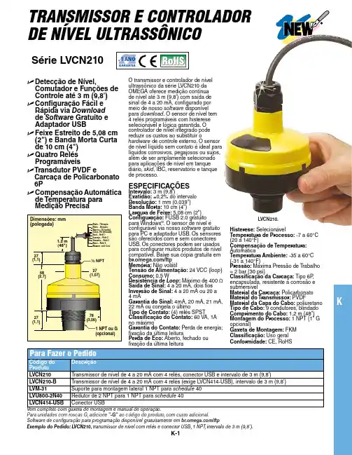
KK-1TRANSMISSOR E CONTROLADOR DE NÍVEL ULTRASSÔNICO Série LVCN210e D etecção de Nível, Comutador e Funções de Controle até 3 m (9,8')e C onfiguração Fácil e Rápida via Download de Software Gratuito e Adaptador USBe F eixe Estreito de 5,08 cm (2") e Banda Morta Curta de 10 cm (4")e Q uatro Relés Programáveise T ransdutor PVDF e Carcaça de Policarbonato 6Pe C ompensação Automática de Temperatura para Medição PrecisaO transmissor e controlador de nível ultrassônico da série LVCN210 da OMEGA oferece medição contínua de nível até 3 m (9,8') com saída de sinal de 4 a 20 mA, configurado por meio de nosso software disponível para download . O sensor de nível tem 4 relés programáveis com histerese selecionável e lógica garantida. O controlador de nível integrado pode reduzir os custos ao substituir o hardware de controle externo. O sensor de nível líquido sem contato é ideal para líquidos corrosivos, pegajosos ou sujos, além de ser amplamente selecionado para aplicações de nível em tanque diário, skid , IBC, reservatório e tanque de processo.ESPECIFICAÇÕES Intervalo: 3 m (9,8')Exatidão: ±0,2% do intervalo Resolução: 1 mm (0,039")Banda Morta: 10 cm (4")Largura de Feixe: 5,08 cm (2")Configuração: FUSB 2.0 gratuito para Windows ®. O sensor de nível é configurável via nosso software gratuito para PC e adaptador USB. Os sensores são oferecidos com e sem conectores USB. Os conectores podem ser usados para configurar muitos produtos de nível compatível. Baixe sua cópia gratuita em /ftp Memória: Não volátil Tensão de Alimentação: 24 VCC (loop )Consumo: 0,5 W Resistência de Loop : Máximo de 400 ΩSaída de Sinal: 4 a 20 mA, dois fios Inversão de Sinal: 4 a 20 mA ou 20 a 4 mA Garantia do Sinal: 4mA, 20 mA, 21 mA, 22 mA ou congela o último Tipo de Contato: (4) relés SPST Classificação do Contato: 60 VA, 1A no máximo Garantia do Contato: Perda de energia; fixação da última leitura Perda de Eco: Aberto, fechado ouPara unidades com roscas G, adicione "-G" ao código do produto, com custo adicional.Software de configuração para programação disponível gratuitamente em /ftp Exemplo do Pedido: LVCN210, transmissor de nível com relés e conector USB, 1 NPT ,intervalo de 3 m (9,8').LVCN210.Histerese: Selecionável Temperatura de Processo: -7 a 60°C (20 a 140°F)Compensação de Temperatura: Automática Temperatura Ambiente: -35 a 60°C (-31 a 140°F)Pressão: Máxima Pressão de T rabalho = 2 bar (30 psi)Classificação da Carcaça: Tipo 6P , encapsulada, resistente à corrosão e submersível Material da Carcaça: Policarbonato Material do Transmissor: PVDF Material da Capa do Cabo: poliuretano Tipo de Cabo: 9 condutores, blindado Comprimento do Cabo: 1,2 m (48")Montagem do Processo: 1 NPT (1" G opcional)Gaxeta de Montagem: FKM Classificação: Uso geral Conformidade: CE, RoHS。
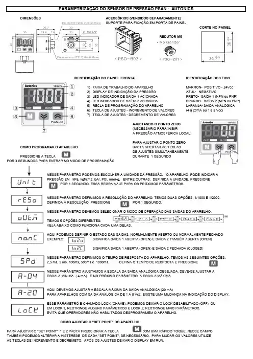
DIMENSÕESSUPORTE PARA FIXAÇÃO EM PORTA DE PAINELCORTE NO PAINELREDUTOR M5IDENTIFICAÇÃO DO PAINEL FRONTAL IDENTIFICAÇÃO DOS FIOS1)FAIXA DE TRABALHO DO APARELHO MARRON- POSITIVO - 24Vcc2)DISPLAY DE INDICAÇÃO DA PRESSÃO AZUL- NEGATIVO3)LED INDICADOR DE SAÍDA 1 ACIONADA4)LED INDICADOR DE SAÍDA 2 ACIONADA5)RECLA DE PROGRAMAÇÃO DO APARELHO6)TECLA DE AJUSTES - INCREMENTO DE VALORES7)TECLA DE AJUSTES - DECREMENTO DE VALORESCOMO PROGRAMAR O APARELHOPRESSIONE A TECLAPOR 3 SEGUNDOS PARA ENTRAR NO MODO DE PROGRAMAÇÃONESSE PARÂMETRO PODEMOS ESCOLHER A UNIDADE DA PRESSÃO. O APARELHO PODE INDICAR APRESSÃO EM kPa, kgf/cm2, bAr, PSI, mmHg, ENTRE OUTRAS. DEFINIDA A UNIDADE, PRESSIONEPOR 1 SEGUNDO. ESSA REGRA VALE PARA OS PRÓXIMOS PARÂMETROS.NESSE PARÂMETRO DEFINIMOS A RESOLUÇÃO DO APARELHO. TEMOS DUAS OPÇÕES: 1/1000 E 1/2000.NESSE PARÂMETRO DEVEMOS SELECIONAR O MODO DE OPERAÇÃO DAS SAÍDAS DO APARELHO.VEJA ABAIXO COMO FUNCIONA CADA UMA DELAS.AQUI PODEMOS DEFINIR O ESTADO DAS SAÍDAS, NORMALMENTE ABERTO OU NORMALMENTE FECHADONESSE PARÂMETRO DEFINIMOS O TEMPO DE RESPOSTA DO APARELHO. TEMOS AS SEGUINTES OPÇÕES:2,5 ms, 5 ms, 100ms, 500ms e 1000ms.NESSE PARÂMETRO AJUSTAMOS A ESCALA DA SAÍDA ANALÓGICA DESEJADA. DEVE-SE AJUSTAR ACOMO AJUSTAR O "SET POINT" DO APARELHOPARA AJUSTAR O "SET POINT" 1 E 2 PASTA PRESSIONAR A TECLA COM UMA RÁPIDO TOQUE. NESSE CAMPOTAMBÉM PODEMOS ALTERAR A HISTERESE DE CADA "SET POINT", SE NECESSÁRIO. PARA MUDAR OS VALORES UTILIZEAS TECLAS DE INCREMENTO E DECREMETO. APÓS OS AJUSTES DEIXAR O DISPLAY EM RUN.MODO MODOMODO。
FTB500 Series Low Flowrate MetersIt is the policy of OMEGA Engineering, Inc. to comply with all worldwide safety and EMC/EMI regulations that apply. OMEGA is constantly pursuing certification of its products to the European New Approach Directives. OMEGA will add the CE mark to every appropriate device upon certification.The information contained in this document is believed to be correct, but OMEGA accepts no liability for anyCONTENTS1. Introduction (2)2. Operation (3)2.1 Principle (3)2.2 Precautions (3)3. Installation (4)3.1 General Piping (4)3.2 Strainers/Filters (5)3.3 Installation Kits (5)4. Maintenance (6)4.1 General (6)4.2 Disassembly (6)4.3 Inspection & Repair (6)4.4 Assembly (8)4.5 Pickup Coil Testing (8)4.6 Trouble Shooting (10)4.7 Spare Parts (11)1IntroductionWe are proud that you have selected an Omega Low Flowrate Meter, the finest precision flow transducer on the market.The Omega FTB500 Series of Low Flowrate Meters are designed to meet the need for a high quality low flow measurement device for service in low to moderate viscosity clean liquids and for gas applications.The information in this manual is provided to assist in the proper installation, use, and maintenance of your instrument.Please take a few minutes to read through this manual before installing and operating your meter. If you have any problems with the meter, refer to the maintenance and troubleshooting sections of this manual.If you need further assistance, contact your local Omega Representative or contact the Omega customer service department by telephone, fax, or email for advice.2Operation2.1PrincipleThe Omega FTB500 Series of Low Flowrate Meters has been developed to meet the need for a low flow measurement device for use with low to moderate viscosity clean liquids and for gas measurement applications.The Omega FTB500 Series of Low Flowrate Meters is a family of low flow rate measurement devices whose design is based on a Pelton Wheel-like rotor. The measured fluid is directed tangentially through a velocity nozzle against the rotor causing it to spin. The pickup coil senses the spinning motion of the rotor through the housing and converts it into a pulsing electrical signal. Summation of the pulsing electrical signal relates directly to the total flow, while the frequency is related to the flow rate.2.2Precautions♦Do not drop the meter. Dropping the meter may result in damage to the meter housing and/or internals.♦Do not operate the meter at flowrates greater than the maximum flowrate marked on the meter. Operating atflowrates greater than the maximum flowrate may over-spin the meter. Over-spinning may result in damage tothe meter.CAUTION:Avoid over-spinning the meter. Over-spinning the meter may result in damage to the meter internals and lead to meterfailure.3 InstallationUpon receipt of the flowmeter carefully inspected it, checking for any indications of damage which may have occurred during shipment. Inspect all packing material carefully for parts or components which may have been packed with the shipment. Refer to the packing list/invoice for a detailed list of items included in the shipment.3.1 General PipingThe Omega FTB500 Series of Low Flowrate Meters is capable of sensing fluid flow in one direction only. The meter housing is marked by a flow direction arrow to indicate the direction of flow through the meter. The meter must be installed in the piping in the correct orientation to ensure the most accurate and reliable operation. Care should be taken in the proper selection of the mating fittings. Size, type of material, and pressure rating should be the same as the flowmeter supplied.When it is expected that flow will be intermittent, the meter should not be mounted at a low point in the piping system. Solids which settle or congeal in the meter may affect meter performance.In order to achieve optimum electrical signal output from the flowmeter, due consideration must be given to its isolation from ambient electrical interference such as nearby motors, trans-formers, and solenoids.A typical flowmeter installation is shown below:Blocking and Bypass valves should be installed if it is necessary to do preventive maintenance on the flowmeter without shutting down the flow system. The Bypass valve can be opened before the Blocking valves are closed allowing the flow to continue while removing the turbine flowmeter for service.BYPASS RUN METER RUNIMPORTANT: All flow lines should be purged prior to installing themeter. To prevent possible damage to the meter, install themeter ONLY in flow lines that are clean and free of debris.Upon initial start-up of the system a spool piece should be installed in place of the flowmeter so that purging of the system can be performed to remove all particle debris which could cause damage to the meter internals. In applications where meter flushing is required after meter service, care should be taken as to not over-spin the meter, as severe meter damage may occur.CAUTION:Avoid over-spinning the meter. Over-spinning the meter may result in damage to the meter internals and lead to meterfailure.3.2Strainers/FiltersThe Omega FTB500 Series of Low Flowrate Meters is designed for use in a clean fluid service. However, the service fluid may carry some particulate material which would need to be removed before reaching the flowmeter. Under these conditions a strainer/filter may be required to reduce the potential hazard of fouling or damage that may be caused by foreign matter.METER SIZE MESH SIZE PARTICLE SIZE(Maximum)¼" to ½"100 .00555/" to 1¼"70 .00881½" to 3"40 .015If a strainer/filter is required in the system, it should be located upstream of the flowmeter taking care that the proper minimum distance is kept between the strainer and flowmeter.3.3Installation KitsInstallation kits for the Omega FTB500 Series of Low Flowrate Meters consist of two lengths of appropriate tubing cut to a length appropriate for the upstream and downstream straight pipe run with appropriate end fittings.4Maintenance4.1GeneralPreventive maintenance for the Omega FTB500 Series of LowFlowrate Meters consists of a thorough general inspection.Remove the meter from the service line and take to a clean workarea. Use the following procedures and exploded component views to remove, inspect, and reinsert the flowmeter internals.4.2Disassembly1.Hold the meter securely using a vise. Meter orientationshould be such that the threaded plug is facing up. Useextreme care not to damage the meter housing or pipingconnections when placing in the vise.ing a large-blade screwdriver, turn the plugcounterclockwise to remove.3.To remove the shaft assembly, carefully thread a 10-32screw into the hole provided in insert. Thread the screwinto the insert until it bottoms out (finger tight only).4.Turn the housing over and slowly and carefully pull theshaft assembly and internals out of the housing. Takecare not to damage the shaft, rotor, and/or bearings.5.Remove and discard the gasket/seal.4.3Inspection & Repair1.Examine the flowmeter internals for signs of corrosionor fouling by foreign materials.2.Examine the shaft, rotor, and bearings for signs of wearand/or damage.3.If wear or damage is present, replace with new parts.NOTE: Clean all of the internals in an approved cleaning solution.Exploded View: C – Hard Carbon Bearing ModelsExploded View: BB - Ball Bearing ModelsRotorRotor4.4 Assembly1.Install any new parts.2.Guide the rotor and bearing assembly onto the shaft.Make sure the rotor is installed with the cup side of thePelton wheel facing the “IN” side of the housing.3.Place a new gasket on the insert. Always use a newgasket.4.Place the shaft assembly insert, gasket, and rotorassembly back into housing by inverting the housing tokeep gasket and rotor assembly in place.5.Install the threaded plug and tighten to 50 ft-lb.4.5Pickup Coil TestingTesting the MAG and MCP (RF) coils consists of measuring the resistance with an ohmmeter. Resistance measurements are to be made when there is no flow through the meter or with the coil removed from the meter housing.1.Measure the resistance between pin A and pin B. Theresistance should be approximately as listed in thefollowing table of some common coils.2.The resistance from any pin to the case should be greaterthan 1 Mohm.COIL DC RESISTANCE(Ohms)MC2PAHT 15.0 ±10%MCP3A 11.5 ±10%PC13-74G 1800 ±10%PC13-74S 1850 ±15%PC24-45G 1350 ±10%PC24-45S 1850 ±15%PC28-13G 120 ±20%PC28-14G 180 ±20%If either resistance measurement fails, replace the pickup coil. Firmly seat the new coil in the flowmeter and tighten the locking nut.4.6Trouble ShootingRefer to the following troubleshooting guide for assistance with possible meter malfunctions:TROUBLE CAUSE REMEDY Fluid will not flow ▪Meter clogged. Clear meter.through the meter ▪Line to meterblocked.Clear line to meter.Reduced flow through the meter ▪Meter partiallyclogged.Clear meter.▪Line to meterpartially blocked.Clear line to meter.Meter readings inaccurate ▪Fluid flowrate isnot within meterflow range.See “Specifications” formin and max flowrates. ▪Meter drag due toworn or damagedparts.Replace worn ordamaged parts.Meter not giving pulse ▪Faulty pickup coil. Replace pickup coil.signal ▪Meter internals notturning due toworn or damagedparts. Replace worn or damaged parts.4.7Spare PartsThe following table contains the suggested spare parts for the Omega FTB500 Series of Low Flowrate Meters:Item No. Qty Part Description1 1 PickupCoil1 1 Seal/GasketAssembly1 1 Rotor1 1 BearingsAssembly1 1 ShaftSpecific meter parts are dependent upon the meter size and model, always have the complete meter model number or serial number available when consulting the factory.WARRANTY/DISCLAIMEROMEGA ENGINEERING, INC. warrants this unit to be free of defects in materials and workmanship for a period of 13 months from date of purchase. OMEGA’s WARRANTY adds an additional one (1) month grace period to the normal one (1) year product warranty to cover handling and shipping time. This ensures that OMEGA’s customers receive maximum coverage on each product.If the unit malfunctions, it must be returned to the factory for evaluation. OMEGA’s Customer Service Department will issue an Authorized Return (AR) number immediately upon phone or written request. U pon examination by OMEGA, if the unit is found to be defective, it will be repaired or replaced at no charge. OMEGA’s WARRANTY does not apply to defects resulting from any action of the purchaser, including but not limited to mishandling, improper interfacing, operation outside of design limits, improper repair, or unauthorized modification.This WARRANTY is VOID if the unit shows evidence of having been tampered with or shows evidence of having been damaged as a result of excessive corrosion; or current, heat, moisture or vibration; improper specification; misapplication; misuse or other operating conditions outside of OMEGA’s control. Components in which wear is not warranted, include but are not limited to contact points, fuses, and triacs.OMEGA is pleased to offer suggestions on the use of its various products. However, OMEGA neither assumes responsibility for any omissions or errors nor assumes liability for any damages that result from the use of its products in accordance with information provided by OMEGA, either verbal or written. OMEGA warrants only that the parts manufactured by the company will be as specified and free of defects. OMEGA MAKES NO OTHER WARRANTIES OR REPRESENTATIONS OF ANY KIND W HATSOEVER, EXPRESSED OR IMPLIED, EXCEPT THAT OF TITLE, AND ALL IMPLIED W ARRANTIES INCLUDING ANY W ARRANTY OF MERCHANTABILITY AND FITNESS FOR A PARTICULAR PURPOSE ARE HEREBY DISCLAIMED. LIMITATION OF LIABILITY: The remedies of purchaser set forth herein are exclusive, and the total liability of OMEGA with respect to this order, whether based on contract, warranty,negligence, indemnification, strict liability or otherwise, shall not exceed the purchase price of the component upon which liability is based. In no event shall OMEGA be liable for consequential, incidental or special damages.CONDITIONS: Equipment sold by OMEGA is not intended to be used, nor shall it be used: (1)as a “Basic Component” under 10 CFR 21 (NRC), used in or with any nuclear installation or activity; or (2) in medical applications or used on humans. Should any Product(s) be used in or with any nuclear installation or activity, medical application, used on humans, or misused in any way, OMEGA assumes no responsibility as set forth in our basic WARRANTY/ DISCLAIMER language, and, additionally, purchaser will indemnify OMEGA and hold OMEGA harmless from any liability or damage whatsoever arising out of the use of the Product(s) in such a manner.RETURN REQUESTS/INQUIRIESDirect all warranty and repair requests/inquiries to the OMEGA Customer Service Department.BEFORE RETU RNING ANY PRODU CT(S) TO OMEGA, PU RCHASER MU ST OBTAIN AN AU THORIZED RETU RN (AR) NU MBER FROM OMEGA’S CU STOMER SERVICE DEPARTMENT (IN ORDER TO AVOID PROCESSING DELAYS). The assigned AR number should then be marked on the outside of the return package and on any correspondence.The purchaser is responsible for shipping charges, freight, insurance and proper packaging to prevent breakage in transit.FOR WARRANTY RETURNS, please havethe following information available BEFOREcontacting OMEGA:1.Purchase Order number under whichthe product was PURCHASED,2.Model and serial number of the productunder warranty, and3.Repair instructions and/or specificproblems relative to the product.FOR NON-WARRANTY REPAIRS,consult OMEGA for current repair charges. Have the following information available BEFORE contacting OMEGA:1. Purchase Order number to cover the COST of the repair,2.Model and serial number of theproduct, and 3.Repair instructions and/or specific problemsrelative to the product.OMEGA’s policy is to make running changes, not model changes, whenever an improvement is possible. This affords our customers the latest in technology and engineering.OMEGA is a registered trademark of OMEGA ENGINEERING, INC.© Copyright 2011 OMEGA ENGINEERING, INC. All rights reserved. This document may not be copied, photocopied,Where Do I Find Everything I Need for Process Measurement and Control?OMEGA…Of Course!Shop online at SMTEMPERATUREⅪߜThermocouple, RTD & Thermistor Probes, Connectors, Panels & AssembliesⅪߜWire: Thermocouple, RTD & ThermistorⅪߜCalibrators & Ice Point ReferencesⅪߜRecorders, Controllers & Process MonitorsⅪߜInfrared PyrometersPRESSURE, STRAIN AND FORCEⅪߜTransducers & Strain GagesⅪߜLoad Cells & Pressure GagesⅪߜDisplacement TransducersⅪߜInstrumentation & AccessoriesFLOW/LEVELⅪߜRotameters, Gas Mass Flowmeters & Flow ComputersⅪߜAir Velocity IndicatorsⅪߜTurbine/Paddlewheel SystemsⅪߜTotalizers & Batch ControllerspH/CONDUCTIVITYⅪߜpH Electrodes, Testers & AccessoriesⅪߜBenchtop/Laboratory MetersⅪߜControllers, Calibrators, Simulators & PumpsⅪߜIndustrial pH & Conductivity EquipmentDATA ACQUISITIONⅪߜData Acquisition & Engineering SoftwareⅪߜCommunications-Based Acquisition SystemsⅪߜPlug-in Cards for Apple, IBM & CompatiblesⅪߜData Logging SystemsⅪߜRecorders, Printers & PlottersHEATERSⅪߜHeating CableⅪߜCartridge & Strip HeatersⅪߜImmersion & Band HeatersⅪߜFlexible HeatersⅪߜLaboratory HeatersENVIRONMENTALMONITORING AND CONTROLⅪߜMetering & Control InstrumentationⅪߜRefractometersⅪߜPumps & TubingⅪߜAir, Soil & Water MonitorsⅪߜIndustrial Water & Wastewater Treatment。
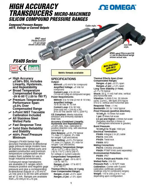
HIGH ACCURACYTRANSDUCERS MICRO-MACHINEDSILICON COMPOUND PRESSURE RANGESCompound Pressure RangesmV/V, Voltage or Current OutputsU High Accuracy±0.08% BSL Includes Linearity, Hysteresis, and Repeatability U Broad Temperature Compensated Range -29 to 85°C (-20 to 185°F)U Premium Temperature Performance Span: ±0.5% OverCompensated Range U 5-Point NIST Traceable Calibration Included U All Stainless Steel Wetted PartsU Fast Response Time U Solid State Reliability and StabilityU 400% Proof Pressure MinimumOmega’s PX409 Series highaccuracy transducers bi-directional gage pressure range models have all stainless steel wetted parts and welded construction and premium temperature compensation which makes them suitable for use in tough industrial environments. Compound range transducers are available in 5 ranges whichmeasure positive and negative gage pressure and give a corresponding bi-directional outputs of ±10 mV/V, ±5 Vdc and 4 to 20 mA with ambient set at 12 mA. Ranges are available from ±10 inH 2O to ±15 psi.SPECIFICATIONSOutput:Millivolt: ±10 mV/V for compound A mplified Voltage: ±5 Vdc for compoundCurrent Loop: 4 to 20 mA(12 mA at 0 psig on compound ranges)Power Requirements:Millivolt: 5 to 10 Vdc (2 mA @ 10 Vdc) Amplified Voltage: 10 to 30 Vdc @ 10 mACurrent Loop: 9 to 30 Vdc [max loop res = [(Vs-9) x 50][9 to 20 Vdc above 105°C (229°F)]CE Compliant: Meets industrial emission and immunity standard EN61326Accuracy (Combined Linearity, Hysteresis and Repeatability): ±0.08% BSL max, calibrated inpositive direction only, with electrical connector upZero Balance: ±0.5% FS typical 1% max (1% typical, 2% max for ranges 1 psi and below)Span Setting: ±0.5% FS typical 1% max (1% typical, 2% max for ranges 1 psi and below)Operating Temperature Range: -45 to 121°C (-49 to 250°F) [-45 to 115°C (-49 to 240°F) for voltage or current outputs]Compensated Temperature: Ranges >5 psi: -29 to 85°C (-20 to 185°F)Ranges ≤5 psi: -17 to 85°C (0 to 185°F)Thermal Effects Zero (@ 0 psig Over Compensated Range): Ranges >5 psi: ±0.5% span Ranges ≤5 psi: ±1.0% spanThermal Effects Span (Over Compensated Range):Ranges >5 psi: ±0.5% span Ranges ≤5 psi: ±1.0% span Long Term Stability (1-Year): ±0.1% FS typicalShock: 50 g, 11 mS half sine, vertical and horizontal axisVibration: 5-2000-5 Hz, 30 minute cycle, Curve L, Mil-Spec 810 figure 514-2-2, vertical and horizontal axis Response Time: <1 msBandwidth: DC to 1 kHz typicalProof Pressure (positive direction): 10 inH 2O: 10 times full scale 1 psi: 6 times full scale2.5 psi and Higher: 4 times full scale (Negative direction 4 times or1 atmosphere whichever is greater)Burst Pressure:10 inH 2O to 15 psi: 1000 psi Electrical Termination:PX409: Integral 2 m (6') cable PX419: mini DIN PX429: Twist-lock PX459: M12Mating Connectors:PX419: CX5302 (included)PX429: PT06F10-6S (sold separately)Environmental Protection: PX409: IP67PX419, PX429 and PX459: IP65Wetted Parts: 316 SSPressure Port: 1⁄4-18 NPT male Calibration: Comes with 5-point calibration certificate (positivereadings only for compound ranges)Weight: 115 to 200 g (4 to 7 oz) depending upon configurationIP67 rated PX409-015CGV ±15 psi range shown actual size.IP65 rated PX419-001CGI ±1 psi bi-directional range shown actual size.PX409 SeriesCable style.mini DIN style.N o w A v a i l a b l e w i t h M 12 C o n n e ct o rProduct LabelHex 22 (0.87) AF¼-18 NPTCustom Models Available!smaller than actual size.Cablestyle.mini DINstyle.* To order cable version with 1⁄2 NPT conduit fitting, specify model PX409C, no extra cost.** To order with 0 to10 Vdc output change “5V” to “10V” in model number, no extra cost. Metric threads and ranges also available.Ordering Examples: PX409-015CGV, cable termination, ±15 psig range, ±10 mV/V output.PX419-001CG5V, mini DIN termination, ±1 psi range, ±5 Vdc, 0 volts @ 0 pressure output.PX429 TWIST LOCK PINOUTPX419 and PX459 PIN OUTPX409 and PX409C CABLE CONNECTIONPX409-015CGVPX429-001CGVPX419-001CGI。
1、日本(OMRON)欧姆龙OMRON欧姆龙集团始创于1933年,目前拥有近87年历史。
现有员工32583人,全球营业额6272亿日元,产品品种达几十万种,涉及工业自动化控制系统、电子元器件、汽车电子、社会系统以及健康医疗设备等广泛领域。
为了适应时代的发展,在公司成立50周年纪念时,公司名称与品牌名称实现了统一,改为“欧姆龙集团(株式会社)”。
创造社会需求,构筑“安心”,“安全”,“环保”“健康”的社会,是欧姆龙集团的发展目标。
2、德国(KROHNE)科隆德国KROHNE公司一直是国际测量领域的先驱,拥有先进技术和丰富的应用经验,使其能够根据市场的要求不断创新,从而提供给全球用户可靠、便捷、先进的测量仪器。
近百年来,KROHNE所研发的一系列新产品,不仅创造出多项世界第一,而且还成为测量领域里的标竿,引导着全球测量仪器的变革和发展。
3、美国(banner)邦纳BANNER始建于1966年,目前有54周年历史。
总部位于美国的明尼苏达州,是全球顶尖的自动化技术专家和整体解决方案提供者。
公司拥有22,000多种产品,具有最为齐全的产品线,经过40多年的发展,现已成为全球最大的光电传感器、测量检测、视觉传感器和机床安全产品的专业制造商之一。
丰富完整的产品选择、迅速的交货期、强大的技术支持以及同行业中首屈一指的研发能力保证了BANNER在同行业中的领军地位。
4、德国(IFM)易福门IFM是德国的一个工控品牌。
1969年德国易福门IFM这家家族企业发明了基于薄膜技术的电感式接近传感器,经过51年的发展从此走上了成功的道路。
今天,“efector”品牌成为了位置与流体传感器、物体识别、诊断和识别系统的代名词,而“ecomat”品牌则是网络和控制系统的杰出结果公司在全球70多个国家拥有5200多名员工,主要为机械制造等行业提供研发和销售服务,用户超过约10万家。
5、瑞士(ABB)ABB是电力和自动化技术领域的全球领导厂商,ABB集团位列全球500强企业。
M3765/1201W h e r e Do I Find Everything I Need forP r ocess Measurement and Control?OMEGA…Of Course!Shop online at T E M P E R A T U RECalibrators &I ce P oint ReferencesLoad C ells &P ressure GagesAir V elocity IndicatorsBenchtop/Laboratory MetersCommunications-Based A cquisition SystemsRecorders,P rinters &P lottersH E A T E RSImmersion &B and HeatersR e f r a c t o m e t e r sIndustrial Water & Wastewater Treatmente-mail:**************Contents Contents (i)WARNING...............................................................................................i i CAUTION................................................................................................i i Chapter 1INTRODUCTION (1)Chapter 2SPECIFICATIONS (2)Chapter 3OPERATION (5)3.1 Initial Inspection and Setup (5)3.2. Connection (5)3.2.1 General Considerations (5)3.2.2 Electrical Considerations (5)3.2.3 Four-Wire Kelvin Lead Connections (5)3.2.4 Thermal emf Considerations (6)3.3 Dial Setting (6)3.4 Environmental Conditions (6)Chapter 4MAINTENANCE (7)4.1Verification of Performance (7)4.1.1 Calibration Interval (7)4.1.2 General Considerations (7)4.1.3 Procedure (7)4.2 Schematic (7)FiguresFigure 1.1 DBX Series High-Accuracy Decade Box (1)Figure 2.1 Typical Operating Guide Affixed to Unit (4)Figure 3.1 Optimal 4-Wire Kelvin Lead Connection (6)Figure 4.1 DBX Series Schematic Diagram (8)WARNINGOBSERVE ALL SAFETY RULES‘WHEN WORKING WITH HIGH VOLTAGES OR LINE VOLTAGES.ELECTRICAL SHOCK HAZARD. DO NOT OPEN CASE.REFER SERVICING TO QUALIFIED PERSONNEL.HIGH VOLTAGE MAY BE PRESENT WITH HIGH VOLTAGE OPTIONS. WHENEVER HAZARDOUS VOLTAGES (> 45 V) ARE USED, TAKE ALL MEASURES TOA VOID ACCIDENTAL CONTACT WITH ANY LIVE COMPONENTS:- USE MAXIMUM INSULATION AND MINIMIZE THE USE OF BARECONDUCTORS.REMOVE POWER WHEN HANDLING UNIT.POST WARNING SIGNS AND KEEP PERSONNEL SAFELY AWAY.CAUTIONDO NOT APPLY ANY VOLTAGES OR CURRENTS TO THE TERMINALS OF THIS INSTRUMENT IN EXCESS OF THE MAXIMUM LIMITS INDICATED ONTHE FRONT PANEL OR THE OPERATING GUIDE LABEL.Chapter 1 INTRODUCTIONThe Omega DB series of resistance decade boxes is a family of instruments providing a very broad choice of high-performance resistance sources. Any num-ber of decades from one to eleven is available in a choice of accuracies.The Omega DB decade box is a precision resis-tance source with excellent characteristics of stabil-ity, temperature coefficient, power coefficient, and frequency response.The Omega DB Series employs very-low-resistance switches with silver alloy contacts. A special design keeps zero resistance to less than 1 mΩ per decade. Self cleaning keeps the silver contacts from becom-ing tarnished when unused, or when only low cur-rents are passed through them. This is most often the case when only minute test currents are drawn by digital multimeters or other test instruments. Contact resistance is stable and remains low and repeatable. High-quality gold-plated tellurium-copper binding posts serve to minimize the thermal emf effects which would artificially reflect a change in dc resistance measure-ments. All other conductors within the instrument, as well as the solder employed, contain no metals or junc-tions that could contribute to thermal emf problems.The standard models offer a choice of one through eleven decades. The panels are clearly labeled show-ing the step size and maximum voltage and current limitations for each decade.With a resolution as low as 1 mΩ and a maximum available resistance of over 111 MΩ, the Omega DB series may be used for exacting precision measure-ment applications requiring high accuracy, good sta-bility, and low zero-resistance. They can be used as components of dc and ac bridges, for calibration, as transfer standards, and as RTD simulators.The Omega DB Series may be rack-mounted to serve as components in measurement and control sys-tems.Figure 1.1. DBX Series High Accuracy Decade BoxChapter 2SPECIFICATIONSFor convenience to the user, the pertinent specifications are given in an OPERATING GUIDE affixed to the case of the instrument. Figure 2.1 shows a typical example.SPECIFICATIONSSingle Decade DBX UnitSINGLE DECADE UNITSORDERING INFORMATIONSingle-decade units are available withresistance as low as 1 m Ω per step toas high as 10 M Ω per step. These unitssatisfy many system applications re-quiring only a single decade whilemaintaining all the quality features ofthe DB series.Each decade is enclosed in an alumi-num case which can serve as a shield.It may be panel mounted and inte-grated with additional units to form potentiometer circuits or other con-figurations.Each unit consists of low-inductance resistors in series, with a high-perfor-mance solid-silver-alloy-contact switch.* For less exacting applications, more economical tolerances are available:- For 0.02% accuracy substitute DBQ in part number in lieu of DBX- For 0.05% accuracy substitute DBA in part number in lieu of DBX- For 0.1% accuracy substitute DBB in part number in lieu of DBX OPTIONS - RM Rack mountable case for standard 19" rack - K Kelvin type 4-terminal binding posts - RO Rear output binding postsChapter 3OPERATION3.2.2 Electrical Considerations In order to make proper use of the full performance capabilities of the DBX unit, especially if low resis-tance or low-resistance increments are important,care must be taken in connecting to the terminals of the decade box.In particular, in order to keep contact resistance to a minimum, the most substantial and secure connec-tion to the binding posts should be made. They ac-cept banana plugs, telephone tips, spade lugs, alli-gator clips, and bare wire. The largest or heaviest mating connection should be made, and, where ap-plicable, the binding posts should be securely tight-ened.These considerations may be relaxed whenever single milliohms are considered significant for the task being performed.3.2.3Four-Wire Kelvin Lead Connections Whenever possible, 4-wire Kelvin leads, the ideal connection, should be employed. Such a connec-tion minimizes the effects of contact resistance and approaches ideal performance.If the four terminals are available as clamps similar to alligator clips, they may be connected to the necks of the binding posts. If the four terminals are avail-able separately, the optimal connection is shown in Figure 3.1, where the current leads are introduced into the top of the binding posts, and the voltage leads at the necks.3.1 Initial Inspection and SetupThis instrument was carefully inspected before ship-ment. It should be in proper electrical and mechanical order upon receipt.An OPERATING GUIDE is attached to the case of the instrument to provide ready reference to speci-fications.3.2 Connection3.2.1General ConsiderationsThe DBX Series Decade unit provides three termi-nals labeled H (high), L (low), and G (ground). The H and L terminals are connected to the ends of the resistance being set; the G terminal is connected to the case. The G terminal may be used as a guard or shield terminal. It may also be connected (using a shorting link) to either terminal to allow two-termi-nal as opposed to three-terminal measurements.In order to make the most stable measurements,determine which is the more sensitive of the two user leads, i.e. the one going into a higher impedance.This lead should be connected to the more protected one of the two DBX terminals. That would either be the DBX terminal that is shorted to the case, or the LOW DBX terminal whenever neither is con-nected to the case.3.2.4 Thermal emf ConsiderationsThe highest-quality low-ernf components are used in the DBX Series. There nevertheless may be some minute thermal emf generated at the test leads where they contact the gold banana jacks.This emf will not reflect itself if an ac measurement instrument is employed. It will also be eliminated if a meter with so called “True Ohm” capability is used. Otherwise it may represent itself as a false compo-nent of the dc resistance measurement.3.3 Dial SettingWhenever the dials are used in positions 0-9, the resulting resistance is simply read directly. Both the decimal point and the steps are clearly marked on the panel.For additional flexibility and range, each decade pro-vides a “10” position setting. This “10” position on any one decade equals the “1” position on the next higher decade. It adds about 11% to the nominal total decade resistance.To determine the resistance obtained when one or more “10” settings are used, simply add “1” to the next higher decade. For example, a setting of3-6-10-0-10 Ω becomes:330000660001010000001010____________________________ TOT37010and a setting of 10-10-10-l0-10.10 Ωbecomes:10100000.01010000.0101000.010100.01010.0.10 1.0________________________________ TOT11111 1.0 3.4 Environmental ConditionsFor optimal accuracy, the decade box should be used in an environment of 23o C. It should be allowed to stabilize at that temperature after any significant tem-perature variation.Humidity should be maintained at laboratory condi-tions. This is especially important if high resistances are involved.Figure 3.1 Optimal 4-Wire Kelvin Lead ConnectionChapter 4 MAINTENANCE4.1Verification of Performance4.1.1Calibration IntervalThe DB Series instruments should be verified for performance at a calibration interval of twelve (12) months. This procedure may be carried out by the user if a calibration capability is available, by Omega, or by a certified calibration laboratory.If the user should choose to perform this procedure, then the considerations below should be observed.4.1.2General ConsiderationsIt is important, whenever testing the DBX Series Decade Units, to be very aware of the capabilities and limitations of the test instruments used. A resis-tance bridge may be employed, and there are di-rect-reading resistance meters or digital multimeters available that can verify the accuracy of these units, especially when used in conjunction with standards that can serve to confirm or improve the accuracy of the testing instrumentSuch test instruments must be significantly more ac-curate than ±(l00ppm+2 mΩ) for all applicable ranges, allowing for a band of uncertainty of the in-strument itself. A number of commercial bridges and meters exist that can perform this task; consult Omega.It is important to allow both the testing instrument and the DBX Substituter to stabilize for a number of hours at the nominal operating temperature of 23O C, and at nominal laboratory conditions of hu-midity. There should be no temperature gradients across the unit under test.Substantial Kelvin type 4-wire test terminals should be used to obtain accurate low-resistance readings. It is convenient, once the zero resistance has been determined, to subtract it from the remaining mea-surements. This can be automatically done in many instruments which have an offset subtraction capa-bility.4.1.3 Procedure1.Confirm the zero resistance of the unit.2.Determine the allowable upper and lowerlimits for each resistance setting of each decade following the specified accuracy. For theDBX series, these limits for any resistance“R” are [R±(0.0001 R + 2 mΩ)]. For the A,B, or Q series, see specifications.3.Confirm that the resistances fall within theselimits after subtraction of the zero resistance.4.If any resistances fall outside these limits, theassociated switch assembly may requirereplacement.4.2 SchematicRefer to Figure 4.1 for a schematic of the DB de-cade unit.8MAINTENANCEFigure 4.1. DB Series Schematic DiagramServicing North America: USA:One Omega Drive, P.O. Box 4047ISO 9001 Certified Stamford CT 06907-0047TEL: (203) 359-1660FAX: (203) 359-7700e-mail:**************Canada:976 BergarLaval (Quebec) H7L 5A1TEL: (514) 856-6928FAX: (514) 856-6886e-mail:*************For immediate technical or application assistance: USA and Canada:Sales Service: 1-800-826-6342 / 1-800-TC-OMEGA®Customer Service: 1-800-622-2378 / 1-800-622-BEST®Engineering Service: 1-800-872-9436 / 1-800-USA-WHEN®TELEX: 996404 EASYLINK: 62968934 CABLE: OMEGA Mexico:En Espan˜ol: (001) 203-359-7803e-mail:*****************FAX: (001) 203-359-7807**************.mxServicing Europe:Benelux:Postbus 8034, 1180 LA Amstelveen, The NetherlandsTEL: +31 (0)20 3472121FAX: +31 (0)20 6434643Toll Free in Benelux: 0800 0993344e-mail:*****************Czech Republic:Rudé armády 1868, 733 01 Karviná 8TEL: +420 (0)69 6311899FAX: +420 (0)69 6311114Toll Free: 0800-1-66342e-mail:*************** France:9, rue Denis Papin, 78190 TrappesTEL: +33 (0)130 621 400FAX: +33 (0)130 699 120Toll Free in France: 0800-4-06342e-mail:**************Germany/Austria:Daimlerstrasse 26, D-75392 Deckenpfronn, GermanyTEL: +49 (0)7056 9398-0FAX: +49 (0)7056 9398-29TollFreeinGermany************e-mail:*************United Kingdom:One Omega Drive, River Bend Technology CentreISO 9002 Certified Northbank, Irlam, ManchesterM44 5BD United KingdomTEL: +44 (0)161 777 6611FAX: +44 (0)161 777 6622Toll Free in United Kingdom: 0800-488-488e-mail:**************.ukWARRANTY/DISCLAIMEROMEGA ENGINEERING, INC. warrants this unit to be free of defects in materials and workmanship for a period of 25 months from date of purchase. OMEGA’s WARRANTY adds an additional one (1) month grace period to the normal two (2) year product warranty to cover handling and shipping time. This ensures that OMEGA’s customers receive maximum coverage on each product.If the unit malfunctions, it must be returned to the factory for evaluation. O M E G A’s Customer Service Department will issue an Authorized Return (AR) number immediately upon phone or written request. Upon examination by OMEGA, if the unit is found to be defective, it will be repaired or replaced at no charge. O M E G A’s WARRANTY does not apply to defects resulting from any action of the purchaser, including but not limited to mishandling, improper interfacing, operation outside of design limits, improper repair, or unauthorized modification. This WARRANTY is VOID if the unit shows evidence of having been tampered with or shows evidence of having been damaged as a result of excessive corrosion; or current, heat, moisture or vibration; improper specification; misapplication; misuse or other operating conditions outside of O M E G A’s control. Components which wear are not warranted, including but not limited to contact points, fuses, and triacs.OMEGA is pleased to offer suggestions on the use of its various products. However, OMEGA neither assumes responsibility for any omissions or errors nor assumes liability for any damages that result from the use of its products in accordance with information provided by OMEGA, either verbal or written. OMEGA warrants only that the parts manufactured by it will be as specified and free of defects. OMEGA MAKES NO OTHER WARRANTIES OR R E P R E S E N T ATIONS OF ANY KIND WHATSOEVER, EXPRESS OR IMPLIED, EXCEPT THAT OF TITLE, AND ALL IMPLIED WARRANTIES INCLUDING ANY WARRANTY OF MERCHANTABILITY AND FITNESS FOR A PA R TICULAR PURPOSE ARE HEREBY DISCLAIMED. LIMITATION OF L I A B I L I T Y: The remedies of purchaser set forth herein are exclusive, and the total liability of OMEGA with respect to this order, whether based on contract, warranty, negligence, indemnification, strict liability or otherwise, shall not exceed the purchase price of the component upon which liability is based. In no event shall OMEGA be liable for consequential, incidental or special damages.CONDITIONS: Equipment sold by OMEGA is not intended to be used, nor shall it be used: (1) as a “Basic Component” under 10 CFR 21 (NRC), used in or with any nuclear installation or activity; or (2) in medical applications or used on humans. Should any Product(s) be used in or with any nuclear installation or a c t i v i t y, medical application, used on humans, or misused in any way, OMEGA assumes no responsibility as set forth in our basic WA R R A N T Y/DISCLAIMER language, and, additionally, purchaser will indemnify OMEGA and hold OMEGA harmless from any liability or damage whatsoever arising out of the use of the Product(s) in such a manner.RETURN REQUESTS/INQUIRIESDirect all warranty and repair requests/inquiries to the OMEGA Customer Service Department. BEFORE RETURNING ANY PRODUCT(S) TO OMEGA, PURCHASER MUST OBTAIN AN AUTHORIZED RETURN (AR) NUMBER FROM OMEGA’S CUSTOMER SERVICE DEPA R TMENT (IN ORDER TO AV O I D PROCESSING DELAYS). The assigned AR number should then be marked on the outside of the return package and on any correspondence.The purchaser is responsible for shipping charges, freight, insurance and proper packaging to prevent breakage in transit.FOR WARRANTY RETURNS, please have thefollowing information available BEFOREcontacting OMEGA:1.Purchase Order number under which the productwas PURCHASED,2.Model and serial number of the product underwarranty, and3.Repair instructions and/or specific problemsrelative to the product.FOR NON-WARRANTY REPAIRS,consult OMEGAfor current repair charges. Have the followinginformation available BEFORE contacting OMEGA:1. Purchase Order number to cover the COSTof the repair,2.Model and serial number of the product, and3.Repair instructions and/or specific problemsrelative to the product.OMEGA’s policy is to make running changes, not model changes, whenever an improvement is possible. This affords our customers the latest in technology and engineering.OMEGA is a registered trademark of OMEGA ENGINEERING, INC.© Copyright 2001 OMEGA ENGINEERING, INC. All rights reserved. This document may not be copied, photocopied, reproduced, translated, or reduced to any electronic medium or machine-readable form, in whole or in part, without the prior written consent of OMEGA ENGINEERING, INC.OMEGAnet®Online Service Internet e-mailw w i n f o@o m e g a.c o mIt is the policy of OMEGA to comply with all worldwide safety and EMC/EMI regulations that apply. OMEGA is constantly pursuing certification of its products to the European New Approach Directives. OMEGA will add the CE mark to every appropriate device upon certification.The information contained in this document is believed to be correct, but OMEGA Engineering, Inc. acceptsno liability for any errors it contains, and reserves the right to alter specifications without notice.WARNING: These products are not designed for use in, and should not be used for, patient-connected applications.。
It is the policy of OMEGA to comply with all worldwide safety and EMC/EMI regulations that apply. OMEGA is constantly pursuing certification of its products to the European New Approach Directives. OMEGA will add the CE mark to every appropriate device upon certification.The information contained in this document is believed to be correct, but OMEGA Engineering, Inc. accepts no liability for any errors it contains,and reserves the right to alter specifications without notice.W ARNING: These products are not designed for use in, and should not be used for , patient-connected applications.Benelux:Postbus 8034, 1180 LA Amstelveen The NetherlandsTEL: +31 (0)20 6418405 FAX: +31 (0)20 6434643Toll Free in Benelux: 0800 0993344e-mail:************Czech Republic:Rude ´arma ´d y 1868, 733 01 Karvina´ 8TEL: +420 (0)69 6311899FAX: +420 (0)69 6311114Toll Free in Czech Republic: 0800-1-66342e-mail:***************France:9, rue Denis Papin, 78190 TrappesTEL: +33 (0)130 621 400 FAX: +33 (0)130 699 120TollFreeinFrance:0800-4-06342e-mail:****************Servicing Europe:USA and Canada:Sales Service:1-800-826-6342/ 1-800-TC-OMEGA ®Customer Service:1-800-622-2378/ 1-800-622-BEST ®Engineering Service:1-800-872-9436/ 1-800-USA-WHEN ® TELEX:996404 EASYLINK:62968934 CABLE:OMEGA USA: ISO 9001 CertifiedOne Omega Drive,P .O.Box 4047Stamford CT 06907-0047TEL:(203) 359-1660FAX:(203) 359-7700e-mail:**************Servicing North America:For immediate technical or application assistance:Mexico:TEL:(001) 800-826-6342FAX:(001) 203-359-7807En Espan ~ol:(001) 203-359-7803e-mail:*******************************.mxGermany/Austria:Daimlerstrasse 26,D-75392 Deckenpfronn,Germany TEL:+49 (0)7056 3017 FAX:+49 (0)7056 8540Toll Free in Germany:0800 TC-OMEGA SM e-mail:*****************United Kingdom: ISO 9002 Certified One Omega Drive River Bend Technology Centre Northbank,Irlam Manchester M44 5EX United Kingdom TEL:+44 (0)161 777 6611 FAX:+44 (0)161 7776622Toll Free in United Kingdom:0800488488e-mail:**************.ukCanada:976 Bergar Laval (Quebec) H7L 5A1TEL:(514) 856-6928FAX:(514) 856-6886e-mail:*************SCR POWER CONTROLLERSTABLE OF CONTENTSGeneral Descriptionand Specifications (1)Firing Modes (2)Installation and Wiring (4)Operation (9)T roubleshooting (15)Parts Lists andOrdering Codes (18)OPERATING INSTRUCTIONSSeries 19 and 39 SCR Power ControllersSeries 91 and 93 SCR Power ControllersSection 1. General DescriptionIntroductionSCR Power Controllers are designed to regulate ac power to electrical heating processes, such as ovens, furnaces, heat sealers, etc. (Note: They are not designed to drive transformers, coils or other inductive-type loads.)The controller accepts an input signal, such as 4-20 mAdc from some signal conditioning device, e.g., a temperature controller. For most processes, the combination of a temperature controller and SCR power controller will provide very accurate, automatic temperature control. For manual operation, a manual control option with a remote potentiometer is available.General SpecificationsInputs:4-20 mAdc standard, or as ordered (seeserial number) minimum voltagerequirements 10 Vdc; all inputselectrically isolated via optical couplingSupply Voltage:110/120; 208/240; 440/480, 575/600Vac, or as ordered (Phase connectionnot critical on 3-phase units)Frequency:50/60 HzAmbient T emperature:30o to 122o F for listed power ratings Cooling:ConvectionProtection:Sub-cycle, current-limiting fuse; transientvoltage suppresionLoad Resistive, 1- or 3-phase - 3-wire Wye or Delta All specifications subject to change.1234567Figure 4a. Wiring scheme for Series 19Z.Figure 4b. Wiring scheme for Series 39Z.3.21 Zero-Cross Zero-cross mode power controllers may only be used with constant resistance heating elements, such as Nichrome. They are NOT intended for high-inrush loads. Depending on the type of element used, you can oversize the load controller.3.22 Phase-AnglePhase-Angle fired power controllers may be used with high-inrush loads if the "soft-start" option is installed.Figure 5a. Wiring scheme for Series 19P.Figure 5b. Wiring scheme for Series 39P .Section 4. OperationSeries19/394.1 Series 19Z/39ZThe Series 19Z and 39Z power controllers are designed to control ac power to electrical heating processes, such as ovens, furnaces, heat sealers, etc. (Note:They are NOT intended to drive transformer coupled or inductive loads.) The controllers consist of power semiconductors (SCRs), properly sized heat sinks, and trigger circuitry. These controllers accept a control signal (e.g., 4-20 mAdc) from a signal conditioning device, such as a temperature controller. The “Z” suffix designates the controller as operating in the Zero Cross, Zero Voltage Switched, or Zero Burst firing mode.A patented trigger circuit turns on the SCRs as close as possible to the point at which the ac sine wave crosses through zero. In effect, this turns the line voltage on and off in full cycles. With an input of 4-20 mA , the output will be FULL OFF below 4 mA and FULL ON at 20 mA. Proportioning action is obtained by varying the number of cycles ON to the number of cycles OFF. The resulting output power is integrated by the heaters to produce smoothly proportional heating that varies directly with the input signal.4.2 Series 19P/39PThe Series 19P and 39P power controllers are designed to control ac power to electrical heating processes, such as ovens, furnaces, heat sealers, etc. (Note: They are NOT designed to drive transformer-coupled loads.) The controllers consist of power semiconductors (SCRs), properly sized heat sinks, and trigger circuitry.These controllers accept a control signal (e.g., 4-20 mAdc) from a signal conditioning device, such as a temperature controller.The “P” Suffix designates the controller as operating in the Phase-Angle firing mode. Providing full proportional control, SCRs are turned ON during each 1/2 cycle at apoint (phase angle) of the ac sine wave, remaining ON for the rest of the1/2 cycle. By varying the phase angle setting, the amount of voltage reaching the load may be adjusted. The output voltage is proportional to the input signal. At 4 mA input, no voltage will be applied to the load; at 20 mA input, the output voltage will almost equal the line voltage.4.3 Voltage Limit Option (Phase-Angle Fired Units Only)The output voltage of the controller can be limited by adjusting the trimmer on the printed circuit board. Turning the adjustment clockwise will increase the out put voltage limit. This control will operate over a range of about 20% to full output. Ordinarily, this adjustment is used to protect heaters that cannot operate on full line voltage, or to limit the maximum heating of a process.4.4 Soft Start Option (Phase-Angle Fired Units Only)The soft start circuitry is used to slowly turn on the voltage from the controller to the load. It is used to protect the controller when it is operating into loads having high-current, turn-on characteristics, e.g., quartz or tungsten heaters. The output voltage will rise from zero to full output over various times, depending on the time option selected.The soft start circuit presents an initial high impedance which is inserted between the signal source and the controller. This impedance decreases in value with time. Soft start action can be seen as the input signal slowly changes from 4-20 mA when full output is required.4.8 TroubleshootingIf the power controller is not functioning properly, refer to these troubleshooting procedures.Symptom:No heat or reduced heat output.Possible Cause(s)Action1. Loss of line voltage.Check powersupply.2. Line fuse or controller fuse blown.Check heater forshort circuit andcorrect problem.3. No input signal.Check signalconditioner.4. Malfunction on trigger board.Consult factory.5. Open SCR Consult factory.Troubleshooting Flowchart Symptom: Heaters will not turn off.Section 6. Model Identification Ordering Codes:Series 19/39NOTESOMEGA’s policy is to make running changes,not model changes,whenever an improvement is possible.This affords our customers the latest in technology and engineering.OMEGA is a registered trademark of OMEGA ENGINEERING,INC.© Copyright 2004 OMEGA ENGINEERING,INC.All rights reserved.This document may not be copied,photocopied,reproduced,trans-lated,or reduced to any electronic medium or machine-readable form,in whole or in part,without the prior written consent of OMEGA WARRANTY/DISCLAIMEROMEGA ENGINEERING, INC. warrants this unit to be free of defects in materials and workmanship for a period of 13 months from date of purchase. OMEGA’s Warranty adds an additional one (1) month grace period to the normal one (1) year product warranty to cover handling and shipping time. This ensures that OMEGA’s customers receive maximum coverage on each product.If the unit malfunctions, it must be returned to the factory for evaluation. OMEGA’s Customer Service Department will issue an Authorized Return (AR) number immediately upon phone or written request.Upon examination by OMEGA, if the unit is found to be defective, it will be repaired or replaced at no charge. OMEGA’s WARRANTY does not apply to defects resulting from any action of the purchaser,including but not limited to mishandling, improper interfacing, operation outside of design limits,improper repair, or unauthorized modification. This WARRANTY is VOID if the unit shows evidence of having been tampered with or shows evidence of having been damaged as a result of excessive cor-rosion; or current, heat, moisture or vibration; improper specification; misapplication; misuse or other operating conditions outside of OMEGA’s control. Components which wear are not warranted, includ-ing but not limited to contact points, fuses, and triacs.OMEGA is pleased to offer suggestions on the use of its various products. However,OMEGA neither assumes responsibility for any omissions or errors nor assumes liability for any dam-ages that result from the use of its products in accordance with information provided by OMEGA,either verbal or written. OMEGA warrants only that the partsmanufactured by it will be as specified and free of defects. OMEGA MAKES NO OTHERWARRANTIES OR REPRESENTATIONS OF ANY KIND WHATSOEVER, EXPRESS OR IMPLIED, EXCEPT THAT OF TITLE, AND ALL IMPLIED WARRANTIES INCLUDING ANY WARRANTY OF MERCHANTABIL-ITY AND FITNESS FOR A PARTICULAR PURPOSE ARE HEREBY DISCLAIMED. LIMITATION OF LIA-BILITY: The remedies of purchaser set forth herein are exclusive, and the total liability of OMEGA with respect to this order, whether based on contract, warranty, negligence, indemnification, strict liability or otherwise, shall not exceed the purchase price of the component upon which liability is based. In no event shall OMEGA be liable for consequential, incidental or special damages.CONDITIONS: Equipment sold by OMEGA is not intended to be used, nor shall it be used: (1) as a “Basic Component” under 10 CFR 21 (NRC), used in or with any nuclear installation or activity; or (2)in medical applications or used on humans. Should any Product(s) be used in or with any nuclear installation or activity, medical application, used on humans, or misused in any way, OMEGA assumes no responsibility as set forth in our basic WARRANTY / DISCLAIMER language, and, additionally, pur-chaser will indemnify OMEGA and hold OMEGA harmless from any liability or damage whatsoever arising out of the use of the Product(s) in such a manner.RETURN REQUESTS/INQUIRIESDirect all warranty and repair requests/inquiries to the OMEGA Customer Service Department.BEFORE RETURNING ANY PRODUCT(S) TO OMEGA,PURCHASER MUST OBTAIN AN AUTHORIZED RETURN (AR) NUMBER FROM OMEGA’S CUSTOMER SERVICE DEPARTMENT (IN ORDER TO AVOID PROCESSING DELAYS).The assigned AR number should then be marked on the outside of the return package and on any correspondence.The purchaser is responsible for shipping charges,freight,insurance and proper packaging to prevent breakage in transit.FOR WARRANTY RETURNS,please have the follow-ing information available BEFORE contacting OMEGA:1.Purchase Order number under which the product was PURCHASED,2.Model and serial number of the product under warranty,and3.Repair instructions and/or specific problems relative to the product.FOR NON-WARRANTY REPAIRS,consult OMEGA for current repair charges.Have the following informa-tion available BEFORE contacting OMEGA:1.Purchase Order number to cover the COST of the repair,2.Model and serial number of the product,and3.Repair instructions and/or specific problems relative to the product.Where Do I Find Everything I Need for Process Measurement and Control?OMEGA…Of Course!Shop online at TEMPERATURE✓Thermocouple, RTD & Thermistor Probes, Connectors,Panels & Assemblies✓Wire:Thermocouple, RTD & Thermistor✓Calibrators & Ice Point References✓Recorders, Controllers & Process Monitors✓Infrared PyrometersPRESSURE, STRAIN AND FORCE✓T ransducers & Strain Gages✓Load Cells & Pressure Gages✓Displacement T ransducers✓Instrumentation & AccessoriesFLOW/LEVEL✓Rotameters, Gas Mass Flowmeters & Flow Computers✓Air Velocity Indicators✓T urbine/Paddlewheel Systems✓T otalizers & Batch ControllerspH/CONDUCTIVITY✓pH Electrodes, T esters & Accessories✓Benchtop/Laboratory Meters✓Controllers, Calibrators, Simulators & Pumps✓Industrial pH & Conductivity EquipmentDATA ACQUISITION✓Data Acquisition & Engineering Software✓Communications-Based Acquisition Systems✓Plug-in Cards for Apple, IBM & Compatibles✓Datalogging Systems✓Recorders, Printers & PlottersHEATERS✓Heating Cable✓Cartridge & Strip Heaters✓Immersion & Band Heaters✓Flexible Heaters✓Laboratory HeatersENVIRONMENTALMONITORING AND CONTROL✓Metering & Control Instrumentation✓Refractometers✓Pumps & T ubing✓Air, Soil & Water Monitors✓Industrial Water & Wastewater T reatment✓pH, Conductivity & Dissolved Oxygen Instruments。
Operator’s Manual:1 0 02 y r a u r b e FSPECIFICATIONS (CONT’D)ACCURACY:4600 Series:From 10% of cont. to max. flow:± 1.5% of readingBelow 10% of cont. flow: ± 2% of reading 4000, 5000 Series:From 20% of cont. to max. flow:± 1% of readingBelow 20% of cont. flow:± 3% of readingMAX. TEMPERATURE:4000 Series:122°F (50°C)4100 Series:190°F (87.7°C)4600 Series:190°F (87.7°C)5000 Series:248°F (120°C)MAX. PRESSURE:4000, 4600 Series:150 PSI5000 Series:250 PSIPULSE OUTPUTS:Reed relay4100P Series: 1 gal./pulse5010 - 5020: 1 or 10 gal./pulse5020X - 5040:10 gal./pulse5060 & 5080:100 gal./pulseFTB4600 HIGH RESOLUTION PULSE OUTPUT:FTB4605:151.4 pulses/gal.FTB4607:75.7 pulses/gal.Requires 6-16 VDC @ 10mA max power;output requires pull-up to positive DC voltage. (OPTICAL PICKUP (= MIN. INCREMENT):5010 -5020X:0.5 gal./pulse5030 & 5040: 1 gal./pulse5060 & 5080: 5 gal./pulseMAX. READING (GAL.):4000 Series:100,000,0005010 - 5040:10,000,0005060 - 5080:100,000,000HOUSING:4000, 4100, 5005 - 5015:Cast brass5020 - 5080:Cast iron4600 Series:BrassBEARING:Ceramic/sapphireTURBINE:High temperature thermoplastic/fiberglass (polyimide) FLOW TRANSFER:Ceramic magnetOTHER WETTED PARTS:Stainless steel, polypropylene, EPDM O-ringNEW MODELINSTALLATION INSTRUCTIONSOf Hall Effect Flow MeterFLOW METER INSTALLATION1.Make sure that the inside of the pipes are totally clean.2.Install Water Meter with union connection.3.Make sure flow direction of water corresponds with flow indicator arrow on flow meter housing. ELECTRICAL CONNECTION TO HALL EFFECT1.Make wiring connection as indicated on diagram below.2.Please note: 3,5 V < U8 < 20 V I out max. = 20 mA3.The pull-up-resistor R should be a min. of 1 k ohms. On installation without C a value of 10 k ohms isrecommended. In case of clicking disturbances due to the contactor (e.g. radiowave receivers being in the area) a wiring with C= 4,7 nF and R > 1 k ohms should be used.Electrical Connection Diagram Impulse CounterEletrical Connection Diagram Impulse Counter Hall Effect (New), rev 12/01WARRANTY/DISCLAIMEROMEGA ENGINEERING, INC. warrants this unit to be free of defects in materials and workmanship for a period of 13 months from date of purchase. OMEGA’s WARRANTY adds an additional one (1) month grace period to the normal one (1) year product warranty to cover handling and shipping time. This ensures that OMEGA’s customers receive maximum coverage on each product.If the unit malfunctions, it must be returned to the factory for evaluation. OMEGA’s Customer Service Department will issue an Authorized Return (AR) number immediately upon phone or written request. Upon examination by OMEGA, if the unit is found to be defective, it will be repaired or replaced at no charge. OMEGA’s WARRANT Y does not apply to defects resulting from any action of the purchaser, including but not limited to mishandling, improper interfacing, operation outside of design limits, improper repair, or unauthorized modification. This WARRANTY is VOID if the unit shows evidence of having been tampered with or shows evidence of having been damaged as a result of excessive corrosion; or current, heat, moisture or vibration; improper specification; misapplication; misuse or other operating conditions outside of OMEGA’s control. Components in which wear is not warranted, include but are not limited to contact points, fuses, and triacs.OMEGA is pleased to offer suggestions on the use of its various products. However, OMEGA neither assumes responsibility for any omissions or errors nor assumes liability for any damages that result from the use of its products in accordance with information provided by OMEGA, either verbal or written. OMEGA warrants only that the parts manufactured by the company will be as specified and free of defects. OMEGA MAKES NO OTHER W ARRANTIES OR REPRESENTATIONS OF ANY KIND W HATSOEVER, EXPRESSED OR IMPLIED, EXCEPT THAT OF TITLE, AND ALL IMPLIED W ARRANTIES INCLUDING ANY W ARRANTY OF MERCHANTABILITY AND FITNESS FOR A PARTICULAR PURPOSE ARE HEREBY DISCLAIMED. LIMITATION OF LIABILITY: The remedies of purchaser set forth herein are exclusive, and the total liability of OMEGA with respect to this order, whether based on contract, warranty, negligence, indemnification, strict liability or otherwise, shall not exceed the purchase price of the component upon which liability is based. In no event shall OMEGA be liable for consequential, incidental or special damages.CONDITIONS: Equipment sold by OMEGA is not intended to be used, nor shall it be used: (1) as a “Basic Component” under 10 CFR 21 (NRC), used in or with any nuclear installation or activity; or (2) in medical applications or used on humans. Should any Product(s) be used in or with any nuclear installation or activity, medical application, used on humans, or misused in any way, OMEGA assumes no responsibility as set forth in our basic WARRANTY / DISCLAIMER language, and, additionally, purchaser will indemnify OMEGA and hold OMEGA harmless from any liability or damage whatsoever arising out of the use of the Product(s) insuch a manner.FOR WARRANTY RETURNS, please have the following information available BEFORE contacting OMEGA:1. P urchase Order number under which the product was PURCHASED,2. M odel and serial number of the product under warranty, and3. R epair instructions and/or specific problems relative to the product.FOR NON-WARRANTY REPAIRS, consult OMEGA for current repair charges. Have the following information available BEFORE contacting OMEGA:1. Purchase Order number to cover the COST of the repair,2. Model and serial number of the product, and 3. R epair instructions and/or specific problems relative to the product.OMEGA’s policy is to make running changes, not model changes, whenever an improvement is possible. T his affords our customers the latest in technology and engineering. OMEGA is a trademark of OMEGA ENGINEERING, INC.© Copyright 2018 OMEGA ENGINEERING, INC. All rights reserved. This document may not be copied, photocopied, reproduced, translated, or reduced to any electronic medium or machine-readable form, in whole or in part, without the prior written consent of OMEGA ENGINEERING, INC.RETURN REQUESTS / INQUIRIESDirect all warranty and repair requests/inquiries to the OMEGA Customer Service Department. BEFORE RET URNING ANY PRODUCT (S) T O OMEGA, PURCHASER MUST OBT AIN AN AUT HORIZED RET URN (AR) NUMBER FROM OMEGA’S CUST OMER SERVICE DEPARTMENT (IN ORDER TO AVOID PROCESSING DELAYS). The assigned AR number should then be marked on the outside of the return package and on any correspondence.The purchaser is responsible for shipping charges, freight, insurance and proper packaging to prevent breakage in transit.***********************The information contained in this document is believed to be correct, but OMEGA accepts no liability for any errors it contains, and reserves the right to alter specifications without notice.Servicing North America:U.S.A. Omega Engineering, Inc. Headquarters: Toll-Free: 1-800-826-6342 (USA & Canada only) Customer Service: 1-800-622-2378 (USA & Canada only) Engineering Service: 1-800-872-9436 (USA & Canada only) Tel: (203) 359-1660 Fax: (203) 359-7700 e-mail:************** For Other Locations Visit /worldwide。
简明操作指南Deltapilot MFMB50, FMB51, FMB52, FMB53静压液位测量本文档为《简明操作指南》;不得替代设备的《操作手册》。
设备的详细信息请参考《操作手册》和其他文档资料:所有设备型号均可通过以下方式查询:–网址:/deviceviewer–智能手机/平板电脑:Endress+Hauser Operations AppKA01034P/28/ZH/04.1471279480Deltapilot M PROFIBUS PAEndress+Hauser Operations App 2Endress+HauserDeltapilot M PROFIBUS PA 目录Endress+Hauser 3目录1 安全指南 . . . . . . . . . . . . . . . . . . . . . . . . . . . . . . . . . . . . . . . . . . . . . . . . . . . . . . .41.1 指定用途 . . . . . . . . . . . . . . . . . . . . . . . . . . . . . . . . . . . . . . . . . . . . . . . . . . . . . . . . . . . . . . . . . . . . . . . . . . . . . . 41.2 安装、调试和操作 . . . . . . . . . . . . . . . . . . . . . . . . . . . . . . . . . . . . . . . . . . . . . . . . . . . . . . . . . . . . . . . . . . . . . . . 41.3 操作安全和过程安全 . . . . . . . . . . . . . . . . . . . . . . . . . . . . . . . . . . . . . . . . . . . . . . . . . . . . . . . . . . . . . . . . . . . . . 41.4 返回 . . . . . . . . . . . . . . . . . . . . . . . . . . . . . . . . . . . . . . . . . . . . . . . . . . . . . . . . . . . . . . . . . . . . . . . . . . . . . . . . . . 51.5安全图标 . . . . . . . . . . . . . . . . . . . . . . . . . . . . . . . . . . . . . . . . . . . . . . . . . . . . . . . . . . . . . . . . . . . . . . . . . . . . . . 52 产品标识 . . . . . . . . . . . . . . . . . . . . . . . . . . . . . . . . . . . . . . . . . . . . . . . . . . . . . . .53 安装 . . . . . . . . . . . . . . . . . . . . . . . . . . . . . . . . . . . . . . . . . . . . . . . . . . . . . . . . . . .63.1 安装位置 . . . . . . . . . . . . . . . . . . . . . . . . . . . . . . . . . . . . . . . . . . . . . . . . . . . . . . . . . . . . . . . . . . . . . . . . . . . . . . 63.2 常规安装指南 . . . . . . . . . . . . . . . . . . . . . . . . . . . . . . . . . . . . . . . . . . . . . . . . . . . . . . . . . . . . . . . . . . . . . . . . . . 63.3 FMB50 . . . . . . . . . . . . . . . . . . . . . . . . . . . . . . . . . . . . . . . . . . . . . . . . . . . . . . . . . . . . . . . . . . . . . . . . . . . . . . . . 73.4 FMB51/FMB52/FMB53 . . . . . . . . . . . . . . . . . . . . . . . . . . . . . . . . . . . . . . . . . . . . . . . . . . . . . . . . . . . . . . . . . . . 73.5 使用悬挂固定夹安装FMB53 . . . . . . . . . . . . . . . . . . . . . . . . . . . . . . . . . . . . . . . . . . . . . . . . . . . . . . . . . . . . . . . 83.6 组装和安装“分离型外壳”型仪表 . . . . . . . . . . . . . . . . . . . . . . . . . . . . . . . . . . . . . . . . . . . . . . . . . . . . . . . . . 93.7 补充安装指南 . . . . . . . . . . . . . . . . . . . . . . . . . . . . . . . . . . . . . . . . . . . . . . . . . . . . . . . . . . . . . . . . . . . . . . . . . 103.8 关闭外壳盖 . . . . . . . . . . . . . . . . . . . . . . . . . . . . . . . . . . . . . . . . . . . . . . . . . . . . . . . . . . . . . . . . . . . . . . . . . . . 103.9安装后检查 . . . . . . . . . . . . . . . . . . . . . . . . . . . . . . . . . . . . . . . . . . . . . . . . . . . . . . . . . . . . . . . . . . . . . . . . . . . 104 接线 . . . . . . . . . . . . . . . . . . . . . . . . . . . . . . . . . . . . . . . . . . . . . . . . . . . . . . . . . .114.1 连接设备 . . . . . . . . . . . . . . . . . . . . . . . . . . . . . . . . . . . . . . . . . . . . . . . . . . . . . . . . . . . . . . . . . . . . . . . . . . . . . 114.2 连接测量单元 . . . . . . . . . . . . . . . . . . . . . . . . . . . . . . . . . . . . . . . . . . . . . . . . . . . . . . . . . . . . . . . . . . . . . . . . . 134.3 电势平衡 . . . . . . . . . . . . . . . . . . . . . . . . . . . . . . . . . . . . . . . . . . . . . . . . . . . . . . . . . . . . . . . . . . . . . . . . . . . . . 134.4连接后检查 . . . . . . . . . . . . . . . . . . . . . . . . . . . . . . . . . . . . . . . . . . . . . . . . . . . . . . . . . . . . . . . . . . . . . . . . . . . 145 操作 . . . . . . . . . . . . . . . . . . . . . . . . . . . . . . . . . . . . . . . . . . . . . . . . . . . . . . . . . .145.1 不带操作菜单操作 . . . . . . . . . . . . . . . . . . . . . . . . . . . . . . . . . . . . . . . . . . . . . . . . . . . . . . . . . . . . . . . . . . . . . . 145.2 通过操作菜单操作 . . . . . . . . . . . . . . . . . . . . . . . . . . . . . . . . . . . . . . . . . . . . . . . . . . . . . . . . . . . . . . . . . . . . . . 165.3 设备标识和地址设定 . . . . . . . . . . . . . . . . . . . . . . . . . . . . . . . . . . . . . . . . . . . . . . . . . . . . . . . . . . . . . . . . . . . . 256 不带操作菜单调试 . . . . . . . . . . . . . . . . . . . . . . . . . . . . . . . . . . . . . . . . . . . . . . .266.1 功能检查 . . . . . . . . . . . . . . . . . . . . . . . . . . . . . . . . . . . . . . . . . . . . . . . . . . . . . . . . . . . . . . . . . . . . . . . . . . . . . 266.2 位置调整 . . . . . . . . . . . . . . . . . . . . . . . . . . . . . . . . . . . . . . . . . . . . . . . . . . . . . . . . . . . . . . . . . . . . . . . . . . . . . 277 通过操作菜单调试(现场显示/ FieldCare) . . . . . . . . . . . . . . . . . . . . . . . . . . . .287.1 功能检查 . . . . . . . . . . . . . . . . . . . . . . . . . . . . . . . . . . . . . . . . . . . . . . . . . . . . . . . . . . . . . . . . . . . . . . . . . . . . . 287.2 调试 . . . . . . . . . . . . . . . . . . . . . . . . . . . . . . . . . . . . . . . . . . . . . . . . . . . . . . . . . . . . . . . . . . . . . . . . . . . . . . . . . 287.3 零位调整 . . . . . . . . . . . . . . . . . . . . . . . . . . . . . . . . . . . . . . . . . . . . . . . . . . . . . . . . . . . . . . . . . . . . . . . . . . . . . 307.4 液位测量 . . . . . . . . . . . . . . . . . . . . . . . . . . . . . . . . . . . . . . . . . . . . . . . . . . . . . . . . . . . . . . . . . . . . . . . . . . . . . 317.5 线性化功能 . . . . . . . . . . . . . . . . . . . . . . . . . . . . . . . . . . . . . . . . . . . . . . . . . . . . . . . . . . . . . . . . . . . . . . . . . . . 417.6压力测量 . . . . . . . . . . . . . . . . . . . . . . . . . . . . . . . . . . . . . . . . . . . . . . . . . . . . . . . . . . . . . . . . . . . . . . . . . . . . . 44安全指南Deltapilot M PROFIBUS PA 1安全指南1.1指定用途Deltapilot M是静压变送器,用于液位和压力测量。
液位测量传感器
信息参考来源:美国OMEGA工业测量
什么是液位测量传感器?
许多行业的过程控制中都使用液位传感器,它们分为两大类。
点液位测量传感器用于指示单个的离散液位高度,即指示预置的液位情况。
通常情况下,此类传感器的作用是上限报警,即指示过量填充情况,或者指示下限报警情况。
连续液位传感器更为复杂,可对整个系统进行液位监视。
它们可测量一定范围内的液位高度,而不是某一点的液位,因此会产生直接与容器中液位相关联的模拟输出。
为建立一个液位测量系统,此输出信号会传送到过程控制回路和可视指示器。
液位测量传感器选型
选择液位测量传感器之前需要考虑的问题包括:
∙测量液体还是固体?
∙应用环境的温度和压力范围是多少?
∙需要点液位测量还是连续测量?
∙需要多大的液位测量范围?
∙所测材料是否导电?
∙所测材料是否会覆盖或堆积在表面上?
∙液体表面是否会产生紊流、泡沫或蒸汽?
∙需要接触式还是非接触式液位测量?
∙需要哪种输出,模拟、继电器、数字显示还是其它?
设计类型
浮动开关
在此类点液位传感器中,磁浮子会随着液体表面移动,并会促发杆体中密封的“舌簧开关”。
这种简单且维护率低的设计不但可快速安装,最大程度地减小冲击、振动和压力,同时还适用于多种介质。
舌簧开关可以是单刀单掷(SPST),也可以是单刀双掷(SPDT)。
非接触式超声波传感器
这类传感器包含一个模拟信号处理器、一个微处理器、多个二-十进制(BCD) 范围开关以及一个输出驱动电路。
脉冲和一个门极信号从微处理器发射出去后,经由模拟信号处理器传送到传感器,促使传感器向液体表面发送超声束。
接着,传感器检测液面反射的回波,将其送回微处理器,并生成表示传感器与液面水平之间距离的数字信息。
通过不断更新所接收的信号,微处理器计算出平均值,从而最终实现液位测定。
使用连续型传感器时,微处理器会将平均值转化为与液位成线性关系的4 到20 mA 模拟信号。
当液位回波未在8 秒内返回传感器时,系统的输出信号将降至4 mA 以下,指示液位过低或管道已空。
使用点传感器时,微处理器会将平均值与BCD 开关设置进行比较,并
对输出继电器上电来指示液位过高或液位过低。
如信号丢失超过8 秒,则继电器断电并恢
复原始状态。
此外,为减轻表面紊流现象,电子部分中加入了半秒延迟。
接触式超声波传感器
这些传感器中包含低能量超声波设备,可测量特定点的液位水平。
接触式超声波传感器由一
个现场安装的传感器和一个固态积分放大器组成,不含任何移动部件,也无需进行校准。
通
常情况下,它们都带有用于连接电源和外部控制设备的端子块。
超声波信号穿过传感器中半
英寸宽的缝隙,并会在其中包含液体时对继电器开关进行控制。
水平安装式传感器的检测平
面在缝隙的中部,竖直安装式传感器的检测平面在缝隙的顶部。
当液位降到这一水平以下时,
超声波信号将减弱并且最终会将继电器切换到之前的状态。
这些传感器用于在容器或管道中自动操作泵、电磁阀和上下限报警。
填充和排空罐体以及测
量液体量时需使用两个此类传感器。
此类传感器适用于大部分液体,它们不受覆盖层、液滴
粘连、泡沫和蒸汽影响。
但充气过多的液体和粘性过大并可塞满传感器缝隙的液体,则可能
导致故障。
电容式液位传感器
与超声波传感器一样,电容式传感器也可以进行点液位测量或连续液位测量。
它们利用探头
监测罐内的液位变化,并以电子方式将输出调整为电容值和电阻值,进而转换成模拟信号。
探头和容器壁相当于电容的两个极板,液体相当于电介质。
由于信号的发送只与液位变化有
关,所以探头上的物料堆积不会产生任何影响。
对于非导电液体容器,则需要两个探头或一
个外部导电片。
探头可分为刚性和柔性两种,通常都使用PTFE 绝缘的导线。
它使用不锈钢作为探头基础金
属,可为非导电液体、颗粒性液体或介电性质较低(介电常数小于4)的液体测量带来更高
的灵敏度。
当没有足够的间隙可以容纳刚性探头时或者在需要很长的探头长度的应用中,必
须使用柔性探头。
刚性探头的稳定性更高,特别是在存在紊流的系统中,因为探头的晃动会
导致信号起伏波动。
液位测量传感器类型
非接触式超声波液位传感器
由于具有多种电源和编程选项可供选择、能够进行RS-232 或RS-485 通讯、具有按钮校准和温度补偿信号,LVU40 系列传感器将连续非接触式液位测量的灵活性提升至一个新的高度。
它们结合了滤波机制,几乎可以消除外围障碍物的所有伪回波,可在0.3 到18.3 m(1 到60')的整个范围内提供高精度测量。
通过与PLC(可编程控制器)或OMEGA CNi 系列控制器配合使用,可实现点液位测量。
雷达液位传感器
对于需要进行非接触式液位测量的应用,经济实惠的LVRD500 雷达变送器可谓是超声波传感器以外的理性之选。
它们非常适合于液体表面存在蒸汽、灰尘或泡沫等可对超声波测量造成阻碍的应用。
其雷达传感器使用微波脉冲技术,可对目标液体进行从天线顶端到缸体底部的跟踪。
这种先进的“回波标记式”信号处理方法可提供不受环境情况影响的可靠的连续脉冲波形。
同时还提供RS-232 和RS-485 型产品。
干料旋桨式液位开关
LVD-800 系列旋桨开关适用于多种颗粒状、丸状和粉状物质。
它采用已获得专利的磁性技术,可对料箱、料斗、料仓和料缸进行故障安全式监视。
具有自诊断功能的微处理器会持续监视轴和电机安装板的旋转,可对物料的存在情况以及机械或电气故障立即做出响应。
磁性传感机制避免了光学系统固有的误动作问题。
采用旋绕式机盖,不使用任何螺栓。
有2 个导管入口,并且大部分型号都有一个状态指示灯。
高温型号可承受399°C (750°F) 的温度。
电容式测量探头
LV3000/4000 系列探头可承受高温和高压并可耐受多种腐蚀物品,能够在恶劣的应用环境中提供可靠的连续液位测量。
它们适用于液体、糊状物和部分固体(导电和不导电均可),其中不含任何移动部件,而且安装简便。
在对输入电源进行整流和滤波、生成射频信号并计算电流变化后,电子线路将产生与过程液位成比例的 4 至20 mA 2 线制输出信号。
方便的零点和量程调整功能,使用户可以对各种变量进行设置,包括介质类型、容器尺寸、杆长度和安装位置。
如在可导电的容器壁附近使用不锈钢探头,则可选择PTFE 绝缘型号来防止短路。