电能质量国际标准 IEEE 1159-1999
- 格式:pdf
- 大小:722.20 KB
- 文档页数:76
电能质量的概念什么是电能质量?电能质量是指通过公用电网供给用户端的交流电能的品质。
理想状态的公用电网应以恒定的频率、正弦波形和标准电压对用户供电。
同时,在三相交流系统中,各相电压和电流的幅值应大小相等、相位对称且互差120°。
但由于系统中的发电机、变压器和线路等设备非线性或不对称,负荷性质多变,加之调控手段不完善及运行操作、外来干扰和各种故障等原因,这种理想的状态并不存在,因此产生了电网运行、电力设备和供用电环节中的各种问题,也就产生了电能质量的概念。
围绕电能质量含义,从不同角度理解通常包括:(1)电压质量:是以实际电压与理想电压的偏差,反映供电企业向用户供应的电能是否合格的概念。
这个定义能包括大多数电能质量问题,但不能包括频率造成的电能质量问题,也不包括用电设备对电网电能质量的影响和污染。
(2)电流质量:反映了与电压质量有密切关系的电流的变化,是电力用户除对交流电源有恒定频率、正弦波形的要求外,还要求电流波形与供电电压同相位以保证高功率因素运行。
这个定义有助于电网电能质量的改善和降低线损,但不能概括大多数因电压原因造成的电能质量问题。
(3)供电质量:其技术含义是指电压质量和供电可靠性,非技术含义是指服务质量。
包括供电企业对用户投诉的反映速度以及电价组成的合理性、透明度等。
( 4 )用电质量:包括电流质量与反映供用电双方相互作用和影响中的用电方的权利、责任和义务,也包括电力用户是否按期、如数交纳电费等。
目前针对电能质量问题研究的主要内容有哪些?目前,研究和解决电能质量问题已成为电力发展的当务之急。
主要研究课题包括:(1)研究谐波对电网电能质量污染的影响并采取相应的对策。
由于钢铁等金属熔炼企业的发展,5 化工行业整流设备的增加,大功率晶闸管整流装置及电力电子器件的开发应用,使公用电网的谐7 次次波影响日趋严重,电源的波形产生了严重的畸变,影响了电网安全可靠运行。
(2)研究谐波对电力计量装置的影响并采取相应的措施。
一、电能质量1、电能质量的定义不管对电能质量给出什么样的定义,电能质量的内涵应该包括如下几个方面的内容,已经取得了普遍的共识解决电能质量测试设备,使用电能质量分析仪。
电压质量:给出实际电压与理想电压间的偏差,以反映供电部门向用户分配的电力是否合格。
电压质量通常包括电压偏差、电压频率偏差、电压不平衡、电磁暂态现象、电压波动与闪变、短时电压变动、电压谐波、电压间谐波、电压缺口、欠电压、过电压等。
电流质量:电流质量与电压质量密切相关。
为了提高电能的传输效率,除了要求用户汲取的电流是单一频率正弦波外,还应尽量保持该电流波形与供电电压相同。
电流质量通常包括电流谐波、间谐波、电流相位超前与滞后、噪声等。
研究电流质量有助于电网电能质量的改善,降低线路损耗,但不能概括大多数因电压原因造成的质量问题,而后者往往并不总是用电造成的。
供电质量:它包括技术含义和非技术含义两部分。
技术含义有电压质量和供电可靠性;非技术含义是指服务质量,包括技术供电部门对用户投诉与抱怨的反应速度和电力价目的透明度等。
用电质量:用电质量反映供用电双方相互作用与影响的责任和义务,它包括技术含义和非技术含义等。
技术含义包括对电力系统电能质量技术指标的影响和要求。
非技术含义是指用电责任和义务的履行质量,如用户是否按时、如数缴纳电费等。
目前,国内外虽然对使用电能质量这一术语及其内涵达成了共识,但是对电能质量确切的定义尚未形成统一的共识。
使用比较广泛的几个定义如下: 定义1:合格电能质量的概念是指,给敏感设备电力和设置的接地系统均适合于该设备正常工作。
这一定义来自IEEE标准化协调委员会给出的power quality(电能质量)的技术定义。
定义2:电能质量是指供电装置在正常工作情况下不中断和不干扰用户使用电力的物理特性。
该定义来自IEC(1000-2-2/4)标准。
根据这一定义,现代电能质量除了保证额定电压和额定功率下的正弦波形外,还包括频率偏差、电压偏差、电压波动与闪变、三相比平衡、波形畸变、所有电压瞬变现象,如冲击脉冲、电压下跌、瞬间中断及供电连续性等。
电能质量标准电能质量即电力系统中电能的质量。
理想的电能应该是完美对称的正弦波。
一些因素会使波形偏离对称正弦,由此便产生了电能质量问题。
一方面我们研究存在哪些影响因素会导致电能质量问题,一方面我们研究这些因素会导致哪些方面的问题,最后,我们要研究如何消除这些因素,从而最大程度上使电能接近正弦波。
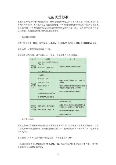
一、电能的质量指标频率:额定频率:50Hz;频率偏差:±0.2Hz(≥3000MW系统)±0.5Hz(<3000MW系统)质量标准:正弦波电压和电流见下表。
谐波的危害与抑制:对于电网、电力设备、通讯都会产生负面影响;二、电压允许偏差用电设备的运行指标和额定寿命是对其额定电压而言的。
当其端子上出现电压偏差时,其运行参数和寿命将受到影响,影响程度视偏差的大小、持续的时间和设备状况而异,电压偏差计算式如下:电压偏差(%)=(实际电压-额定电压)/额定电压×100%《电能质量供电电压允许偏差》(GB12325-90)规定电力系统在正常运行条件下,用户受电端供电电压的允许偏差为:(1)35kV及以上供电以上正、负偏差的绝对值之和小于10%,对电压质量有特殊要求的用户为额定电压的+5%~-5%;(2)10kV及以下高压供电和低压电力用户为额定电压的+7%~-7%;(3)低压照明用户为额定电压的+5%~-10%。
为了保证用电设备的正常运行,在综合考虑了设备制造和电网建设的经济合理性后,对各类用户设备规定了如上的允许偏差值,此值为工业企业供配电系统设计提供了依据。
三、改善电压偏差的主要措施1、就地进行无功功率补偿,及时调整无功功率补偿量,无功负荷的变化在电网各级系统中均产生电压偏差,它是产生电压偏差的源,因此,就地进行无功功率补偿,及时调整无功功率补偿量,从源上解决问题,是最有效的措施。
2、调整同步电动机的励磁电流,在铭牌规定植的范围内适当调整同步电动机的励磁电流,使其超前或滞后运行,就能产生超前或滞后的无功功率,从而达到改善网络负荷的功率因数和调整电压偏差的目的。
提高10kV线路重合闸成功率的措施发表时间:2019-12-16T13:59:02.330Z 来源:《基层建设》2019年第26期作者:吕峰[导读] 摘要:10kV配电线路点多、面广、线长,分为架空、电缆和混合线路,线路稳定运行受外力破坏、恶略天气、设备等多方面因素影响。
国网山东省电力公司邹城市供电公司 273500摘要:10kV配电线路点多、面广、线长,分为架空、电缆和混合线路,线路稳定运行受外力破坏、恶略天气、设备等多方面因素影响。
影响因素的复杂化、线路条件的参差不齐,造成线路跳闸次数多,且重合闸成功率低。
因此,本文针对如何提高10kV线路重合闸成功率进行了多维度的分析,从管理和治理两方面双管齐下,有效降低线路的故障率且提升线路重合闸成功率。
关键词:10kV线路;重合闸;故障率;成功率引言某供电局10kV配电线路155条,全年共发生跳闸292条次,其中重合成功的10kV线路231条次,重合闸成功率为79.1%。
重合闸失败达61条次,经统计,造成重合不成功的原因如表1所示。
针对以上问题,采取如下措施,从管理方面有效降低线路故障跳闸次数,从技术措施方面进一步提升线路重合闸成功率。
一、减少外力破坏导致的线路故障1.1加大宣传力度,保护电力设施运检部、安监部针对专变用户、施工企业开展电力安全知识普及工作,号召各部门深入开展电力行政执法宣传工作,广泛发动全旗人民共同参与。
通过开展“三百活动”将电力安全知识、电力服务电话宣传至用户家中,通过宣传日与各企业、学校、政府部门组织开展安全用电知识讲解、电力宣传手册发放,号召大家安全用电、保护电力设施。
同时,对施工工地做到闭环管理,及时下发《安全防护通知书》和各种电力设施保护宣传单,对于电缆线路附近的挖掘施工和架空线路附近的吊装施工派专人蹲守,及时制止施工人员的不安全行动,向他们宣传保护电力设施安全的责任和义务,严防违规行为危害电力设施安全,力争减少此类案件的发生。
电网电能质量标准随着国民经济和科学技术的蓬勃发展,冶金、化学等现代化大工业和电气化铁路的发展,电网负荷加大,电力系统中的非线性负荷(硅整流设备、电解设备、电力机车)及冲击性、波动性负荷(电弧炉、轧钢机、电力机车运行)使得电网发生波形畸变(谐波)、电压波动、闪变、三相不平衡,非对称性(负序)和负荷波动性日趋严重。
电能质量的下降严重地影响了供用电设备的安全、经济运行,降低了人民的生活质量。
所以在世界各国都十分重视电能质量的管理。
衡量电能质量的主要指标是电网频率和电压质量。
频率质量指标为频率允许偏差;电压质量指标包括允许电压偏差、允许波形畸变率(谐波)、三相电压允许不平衡度以及允许电压波动和闪变。
国家技术监督局已公布了上述电能质量的五个国家标准。
我国《电力法》明确规定"供电企业应当保证供给用户的供电质量符合国家标准,对公用供电设施引起的供电质量问题,应当及时处理",在《供电营业规则》中也明确规定用户的非线性负荷、冲击负荷、波动负荷、非对称负荷对供电质量产生影响或对安全运行构成干扰和妨碍时,用户必须采取措施予以消除,如不采取措施或采取措施不力,达不到国家标准,供电企业可中止对其供电。
在市场经济条件下,供电企业有依法向用户提供质量合格电能产品的责任,用户也有依法用电,不污染电网的义务。
因此如何加强电能质量管理,提高电能质量,是市场经济条件下,电网建设管理中必须认真探讨的重要课题。
本文主要介绍电能质量的具体指标。
1.电网频率我国电力系统的标称频率为50Hz ,GB/T15945-1995《电能质量一电力系统频率允许偏差》中规定:电力系统正常频率偏差允许值为±0.2Hz,当系统容量较小时,偏差值可放宽到±0.5Hz,标准中没有说明系统容量大小的界限。
在《全国供用电规则》中规定"供电局供电频率的允许偏差:电网容量在300万千瓦及以上者为±0.2HZ;电网容量在300万千瓦以下者,为±0.5HZ。
电解铝对电能质量的要求一、电能质量定义:IEEE: 国际电力电子工程师协会IEEE对电能质量的定义是:“合格电能质量的概念指给敏感设备提供的电力和设置的接地系统是均适合于该设备正常工作的”,并已正式采用了“Power quality'’(电能质量)这一术语。
这提醒我们,在许多情况下,接地系统对电能质量的确存在很大的影响,而过去并没有引起足够的重视。
但这个定义的缺点是不够直接和简明。
IEC: 国际电工委员会IEC没有采用“Power quality'’这一术语,而是提出使用“EMC'’(电磁兼容)的概念,它对电磁兼容的定义是:“系统或设备在所处的电磁环境中能正常工作,同时不对其它系统和设备造成干扰”。
指出和强调设备与设备之间、电源与设备之间的相互作用和影响,并确定了谐波电压的兼容性水平。
EMC采用“排放”反映电流质量问题,表示设备产生的电磁污染;采用“抗扰”反映电压质量问题,表示设备免除电磁污染的能力。
IEC以此为基础制定了一系列相关的电磁兼容性技术报告和文件。
由于电磁兼容的技术术语与电能质量术语有很大的重叠性,包括了许多同义词,同时EMC提出的计算电气化铁路牵引站注入电网谐波电流允许值的原则和方法,在现场应用中与电网运行的实际情况并不完全吻合,因而也受到一些非议。
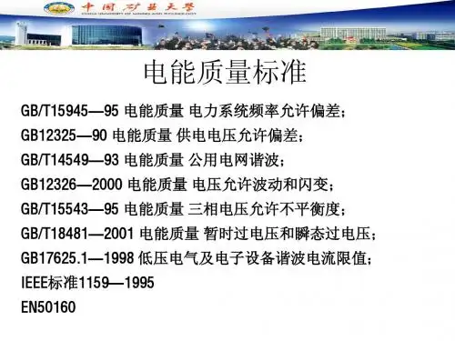
二、我国电能质量标准我过电能质量标准主要有六个,即:《电能质量——公用电网谐波》 GB/T 14549——93;《电能质量——供电电压允许偏差》 GB 12325——90;《电能质量——电压允许波动和闪变》 GB 12326——2000;《电能质量——三相电压允许不平衡度》 GB/T 15543——95;《电能质量——电力系统频率允许偏差》 GB 15945——95;《电能质量——暂时过电压和瞬态过电压》 GB/T 18481——2001;根据我国电能质量标准,主要从以下几个方面对电能质量进行了分析:1、供电电压允许偏差供电电压允许偏差是电能质量的一项基本指标。
电气设备电能质量的规范要求电气设备在供电过程中对电能质量的要求越来越高。
为了确保电气设备运行的可靠性和稳定性,各种标准和规范被制定出来,以规范电气设备电能质量的要求。
本文将介绍一些电气设备在电能质量方面需要满足的规范要求。
一、电能质量的概念和分类电能质量是指供电系统的电参数能够满足电气设备的正常操作要求,没有导致设备故障或性能下降的电气现象。
根据其影响因素和影响程度,电能质量可以被分为几个方面:电压质量、电流质量、频率质量、波形质量和扰动质量等。
不同应用场景下,对这些方面的要求可能有所不同。
二、电压质量的规范要求电压质量是指供电系统提供给用户设备的电压参数,包括电压的大小、偏差、波动和闪变等。
电压质量的规范要求多通过标准和规范文件来进行确定。
国家和国际上广泛采用的一些标准和规范有:国家标准GB/T 12325-1990《电力系统变电所电力负荷电压(电力负荷电压波动)的规范》、国际标准IEC 61000-4-30《电力质量测量—电力负荷电压特性测量的方法》等。
这些标准和规范文件对电压的最大允许偏差、短时电压闪变限值等进行了规定,以确保电压质量能够满足设备的运行要求。
三、电流质量的规范要求电流质量是指电气设备运行过程中所需要的电流参数,包括电流的大小、波形失真和谐波等。
电流质量对于设备的运行稳定性和安全性有重要影响。
国内外有一些标准和规范文件对电流质量进行了规定。
例如,国家标准GB/T 12326-1990《电源设备、电网系统电流质量的规范》、IEEE Std 519-1992《Recommended Practices and Requirements for Harmonic Control in Electrical Power Systems》等。
这些标准和规范文件主要针对设备运行过程中电流的谐波进行了限制,以确保谐波不会对系统造成过大的影响。
四、频率质量的规范要求供电系统的频率稳定性对电气设备的正常运行有着重要的影响。
电网电能质量标准随着国民经济和科学技术的蓬勃发展,冶金、化学等现代化大工业和电气化铁路的发展,电网负荷加大,电力系统中的非线性负荷(硅整流设备、电解设备、电力机车)及冲击性、波动性负荷(电弧炉、轧钢机、电力机车运行)使得电网发生波形畸变(谐波)、电压波动、闪变、三相不平衡,非对称性(负序)和负荷波动性日趋严重。
电能质量的下降严重地影响了供用电设备的安全、经济运行,降低了人民的生活质量。
所以在世界各国都十分重视电能质量的管理。
衡量电能质量的主要指标是电网频率和电压质量。
频率质量指标为频率允许偏差;电压质量指标包括允许电压偏差、允许波形畸变率(谐波)、三相电压允许不平衡度以及允许电压波动和闪变。
国家技术监督局已公布了上述电能质量的五个国家标准。
我国《电力法》明确规定"供电企业应当保证供给用户的供电质量符合国家标准,对公用供电设施引起的供电质量问题,应当及时处理",在《供电营业规则》中也明确规定用户的非线性负荷、冲击负荷、波动负荷、非对称负荷对供电质量产生影响或对安全运行构成干扰和妨碍时,用户必须采取措施予以消除,如不采取措施或采取措施不力,达不到国家标准,供电企业可中止对其供电。
在市场经济条件下,供电企业有依法向用户提供质量合格电能产品的责任,用户也有依法用电,不污染电网的义务。
因此如何加强电能质量管理,提高电能质量,是市场经济条件下,电网建设管理中必须认真探讨的重要课题。
本文主要介绍电能质量的具体指标。
1.电网频率我国电力系统的标称频率为50Hz ,GB/T15945-1995《电能质量一电力系统频率允许偏差》中规定:电力系统正常频率偏差允许值为±0.2Hz,当系统容量较小时,偏差值可放宽到±0.5Hz,标准中没有说明系统容量大小的界限。
在《全国供用电规则》中规定"供电局供电频率的允许偏差:电网容量在300万千瓦及以上者为±0.2HZ;电网容量在300万千瓦以下者,为±0.5HZ。
电能质量指标第5章电能质量指标5.1电能质量指标概述电能质量问题涉及多学科不同的领域,主要和发⽣在电⽹中的电磁现象相关,因⽽与电磁兼容领域有着较⼤的知识交叉。
关于电能质量,⽬前还没有⼀个被各⽅普遍接受的定义。
美国电⽓电⼦⼯程师协会IEEE采⽤“Power quality”这⼀术语描述电能质量,定义为:合格电能质量的概念是指给敏感设备提供的电⼒和设备的接地系统是均适合于该设备正常⼯作的。
这⼀定义主要基于敏感设备进⾏的。
通俗地,可以这样认为:电能质量是与电⼒系统安全经济运⾏相关的、能够对⽤户正常⽣产⼯艺过程及产品质量产⽣影响的电⼒供应的综合技术指标描述。
它涉及电压电流波形形状、幅值及其频率这三⼤基本要素。
电能质量指标的下降是继发电环节以后理想电能在输配供这⼀延续环节中被“污染”造成的。
相当于在理想电能载体上所依附的其它“坏”信息,其主要影响因素包括电⽹结构缺陷、电⽓设备可靠性指标及维护缺陷、继电保护缺陷、环境⽓候及外来因素如雷电等因素、供电设备⾮线性特性、不同⽤户的负荷⽤电特性等。
⼀般来说,描述电能质量的技术参数位该具有明确的物理意义,要能够进⾏监测、评判,并能够根据相关理论研制出有效的控制产品。
⽬前所认识的电能质量问题以电⽹运⾏⽅式⽽⾔可以粗略地分为稳态电能质量问题及暂态电能质量问题,但这两类问题在许多⽅⾯⼜相互交织在⼀起,因此应正确对待。
稳态电能质量参数刻划了电⼒系统稳态运⾏⽅式下的运⾏状态,主要参数包括电压偏差、频率偏差、三相不平衡度、谐波电压电流、电压波动闪变等5类电能质量指标。
稳态电能质量影响范围⼴,程度深,并且具有累积效应。
⽬前,对稳态电能质量的研究已趋于深⼊.IEC及我国均有严格的限值标准,针对稳态电能质量的监测⽅法、监测设备及其监测系统、专业的分析仿真软件、控制⼿段及其控制设备均较成熟,发挥着越来越重要的作⽤。
所谓暂态电能质量即电⼒系统暂态事件或局部暂态事件所引起的运⾏参数的变化以有效值为出发点。
IEEE Std 1159-1995 IEEE Recommended Practice for Monitoring Electric Power QualitySponsorIEEE Standards Coordinating Committee 22 onPower QualityApproved June 14, 1995IEEE Standards BoardAbstract: The monitoring of electric power quality of ac power systems, definitions of power quality terminology, impact of poor power quality on utility and customer equipment, and the measurement of electromagnetic phenomena are covered.Keywords: data interpretation, electric power quality, electromagnetic phenomena, monitoring, power quality definitionsIEEE Standards documents are developed within the Technical Committees of the IEEE Societies and the Standards Coordinating Committees of the IEEE Standards Board. Members of the committees serve voluntarily and without compensation. They are not necessarily members of the Institute. The standards developed within IEEE represent a consensus of the broad expertise on the subject within the Institute as well as those activities outside of IEEE that have expressed an interest in partici-pating in the development of the standard.Use of an IEEE Standard is wholly voluntary. The existence of an IEEE Standard does not imply that there are no other ways to produce, test, measure, purchase, mar-ket, or provide other goods and services related to the scope of the IEEE Standard. Furthermore, the viewpoint expressed at the time a standard is approved and issued is subject to change brought about through developments in the state of the art and com-ments received from users of the standard. Every IEEE Standard is subjected to review at least every Þve years for revision or reafÞrmation. When a document is more than Þve years old and has not been reafÞrmed, it is reasonable to conclude that its contents, although still of some value, do not wholly reßect the present state of the art. Users are cautioned to check to determine that they have the latest edition of any IEEE Standard.Comments for revision of IEEE Standards are welcome from any interested party, regardless of membership afÞliation with IEEE. Suggestions for changes in docu-ments should be in the form of a proposed change of text, together with appropriate supporting comments.Interpretations: Occasionally questions may arise regarding the meaning of portions of standards as they relate to speciÞc applications. When the need for interpretations is brought to the attention of IEEE, the Institute will initiate action to prepare appro-priate responses. Since IEEE Standards represent a consensus of all concerned inter-ests, it is important to ensure that any interpretation has also received the concurrence of a balance of interests. For this reason IEEE and the members of its technical com-mittees are not able to provide an instant response to interpretation requests except in those cases where the matter has previously received formal consideration.Comments on standards and requests for interpretations should be addressed to:Secretary, IEEE Standards Board445 Hoes LaneP.O. Box 1331Piscataway, NJ 08855-1331USAIntroduction(This introduction is not part of IEEE Std 1159-1995, IEEE Recommended Practice for Monitoring Electric Power Quality.)This recommended practice was developed out of an increasing awareness of the difÞculty in comparing results obtained by researchers using different instruments when seeking to characterize the quality of low-voltage power systems. One of the initial goals was to promote more uniformity in the basic algorithms and data reduction methods applied by different instrument manufacturers. This proved difÞcult and was not achieved, given the free market principles under which manufacturers design and market their products. However, consensus was achieved on the contents of this recommended practice, which provides guidance to users of monitoring instruments so that some degree of comparisons might be possible.An important Þrst step was to compile a list of power quality related deÞnitions to ensure that contributing parties would at least speak the same language, and to provide instrument manufacturers with a common base for identifying power quality phenomena. From that starting point, a review of the objectives of moni-toring provides the necessary perspective, leading to a better understanding of the means of monitoringÑthe instruments. The operating principles and the application techniques of the monitoring instruments are described, together with the concerns about interpretation of the monitoring results. Supporting information is provided in a bibliography, and informative annexes address calibration issues.The Working Group on Monitoring Electric Power Quality, which undertook the development of this recom-mended practice, had the following membership:J. Charles Smith, Chair Gil Hensley, SecretaryLarry Ray, Technical EditorMark Andresen Thomas Key John RobertsVladi Basch Jack King Anthony St. JohnRoger Bergeron David Kreiss Marek SamotyjJohn Burnett Fran•ois Martzloff Ron SmithJohn Dalton Alex McEachern Bill StuntzAndrew Dettloff Bill Moncrief John SullivanDave GrifÞth Allen Morinec David VannoyThomas Gruzs Ram Mukherji Marek WaclawlakErich Gunther Richard Nailen Daniel WardMark Kempker David Pileggi Steve WhisenantHarry RauworthIn addition to the working group members, the following people contributed their knowledge and experience to this document:Ed Cantwell Christy Herig Tejindar SinghJohn Curlett Allan Ludbrook Maurice TetreaultHarshad MehtaiiiThe following persons were on the balloting committee:James J. Burke David Kreiss Jacob A. RoizDavid A. Dini Michael Z. Lowenstein Marek SamotyjW. Mack Grady Fran•ois D. Martzloff Ralph M. ShowersDavid P. Hartmann Stephen McCluer J. C. SmithMichael Higgins A. McEachern Robert L. SmithThomas S. Key W. A. Moncrief Daniel J. WardJoseph L. KoepÞnger P. Richman Charles H. WilliamsJohn M. RobertsWhen the IEEE Standards Board approved this standard on June 14, 1995, it had the following membership:E. G. ÒAlÓ Kiener, Chair Donald C. Loughry,Vice ChairAndrew G. Salem,SecretaryGilles A. Baril Richard J. Holleman Marco W. MigliaroClyde R. Camp Jim Isaak Mary Lou PadgettJoseph A. Cannatelli Ben C. Johnson John W. PopeStephen L. Diamond Sonny Kasturi Arthur K. ReillyHarold E. Epstein Lorraine C. Kevra Gary S. RobinsonDonald C. Fleckenstein Ivor N. Knight Ingo RuschJay Forster*Joseph L. KoepÞnger*Chee Kiow TanDonald N. Heirman D. N. ÒJimÓ Logothetis Leonard L. TrippL. Bruce McClung*Member EmeritusAlso included are the following nonvoting IEEE Standards Board liaisons:Satish K. AggarwalRichard B. EngelmanRobert E. HebnerChester C. TaylorRochelle L. SternIEEE Standards Project EditorivContentsCLAUSE PAGE 1.Overview (1)1.1Scope (1)1.2Purpose (2)2.References (2)3.Definitions (2)3.1Terms used in this recommended practice (2)3.2Avoided terms (7)3.3Abbreviations and acronyms (8)4.Power quality phenomena (9)4.1Introduction (9)4.2Electromagnetic compatibility (9)4.3General classification of phenomena (9)4.4Detailed descriptions of phenomena (11)5.Monitoring objectives (24)5.1Introduction (24)5.2Need for monitoring power quality (25)5.3Equipment tolerances and effects of disturbances on equipment (25)5.4Equipment types (25)5.5Effect on equipment by phenomena type (26)6.Measurement instruments (29)6.1Introduction (29)6.2AC voltage measurements (29)6.3AC current measurements (30)6.4Voltage and current considerations (30)6.5Monitoring instruments (31)6.6Instrument power (34)7.Application techniques (35)7.1Safety (35)7.2Monitoring location (38)7.3Equipment connection (41)7.4Monitoring thresholds (43)7.5Monitoring period (46)8.Interpreting power monitoring results (47)8.1Introduction (47)8.2Interpreting data summaries (48)8.3Critical data extraction (49)8.4Interpreting critical events (51)8.5Verifying data interpretation (59)vANNEXES PAGE Annex A Calibration and self testing (informative) (60)A.1Introduction (60)A.2Calibration issues (61)Annex B Bibliography (informative) (63)B.1Definitions and general (63)B.2Susceptibility and symptomsÑvoltage disturbances and harmonics (65)B.3Solutions (65)B.4Existing power quality standards (67)viIEEE Recommended Practice for Monitoring Electric Power Quality1. Overview1.1 ScopeThis recommended practice encompasses the monitoring of electric power quality of single-phase and polyphase ac power systems. As such, it includes consistent descriptions of electromagnetic phenomena occurring on power systems. The document also presents deÞnitions of nominal conditions and of deviations from these nominal conditions, which may originate within the source of supply or load equipment, or from interactions between the source and the load.Brief, generic descriptions of load susceptibility to deviations from nominal conditions are presented to identify which deviations may be of interest. Also, this document presents recommendations for measure-ment techniques, application techniques, and interpretation of monitoring results so that comparable results from monitoring surveys performed with different instruments can be correlated.While there is no implied limitation on the voltage rating of the power system being monitored, signal inputs to the instruments are limited to 1000 Vac rms or less. The frequency ratings of the ac power systems being monitored are in the range of 45Ð450 Hz.Although it is recognized that the instruments may also be used for monitoring dc supply systems or data transmission systems, details of application to these special cases are under consideration and are not included in the scope. It is also recognized that the instruments may perform monitoring functions for envi-ronmental conditions (temperature, humidity, high frequency electromagnetic radiation); however, the scope of this document is limited to conducted electrical parameters derived from voltage or current measure-ments, or both.Finally, the deÞnitions are solely intended to characterize common electromagnetic phenomena to facilitate communication between various sectors of the power quality community. The deÞnitions of electromagnetic phenomena summarized in table 2 are not intended to represent performance standards or equipment toler-ances. Suppliers of electricity may utilize different thresholds for voltage supply, for example, than the ±10% that deÞnes conditions of overvoltage or undervoltage in table 2. Further, sensitive equipment may mal-function due to electromagnetic phenomena not outside the thresholds of the table 2 criteria.1IEEEStd 1159-1995IEEE RECOMMENDED PRACTICE FOR 1.2 PurposeThe purpose of this recommended practice is to direct users in the proper monitoring and data interpretation of electromagnetic phenomena that cause power quality problems. It deÞnes power quality phenomena in order to facilitate communication within the power quality community. This document also forms the con-sensus opinion about safe and acceptable methods for monitoring electric power systems and interpreting the results. It further offers a tutorial on power system disturbances and their common causes.2. ReferencesThis recommended practice shall be used in conjunction with the following publications. When the follow-ing standards are superseded by an approved revision, the revision shall apply.IEC 1000-2-1 (1990), Electromagnetic Compatibility (EMC)ÑPart 2 Environment. Section 1: Description of the environmentÑelectromagnetic environment for low-frequency conducted disturbances and signaling in public power supply systems.1IEC 50(161)(1990), International Electrotechnical V ocabularyÑChapter 161: Electromagnetic Compatibility. IEEE Std 100-1992, IEEE Standard Dictionary of Electrical and Electronic Terms (ANSI).2IEEE Std 1100-1992, IEEE Recommended Practice for Powering and Grounding Sensitive Electronic Equipment (Emerald Book) (ANSI).3. DeÞnitionsThe purpose of this clause is to present concise deÞnitions of words that convey the basic concepts of power quality monitoring. These terms are listed below and are expanded in clause 4. The power quality commu-nity is also pervaded by terms that have no scientiÞc deÞnition. A partial listing of these words is included in 3.2; use of these terms in the power quality community is discouraged. Abbreviations and acronyms that are employed throughout this recommended practice are listed in 3.3.3.1 Terms used in this recommended practiceThe primary sources for terms used are IEEE Std 100-19923 indicated by (a), and IEC 50 (161)(1990) indi-cated by (b). Secondary sources are IEEE Std 1100-1992 indicated by (c), IEC-1000-2-1 (1990) indicated by (d) and UIE -DWG-3-92-G [B16]4. Some referenced deÞnitions have been adapted and modiÞed in order to apply to the context of this recommended practice.3.1.1 accuracy: The freedom from error of a measurement. Generally expressed (perhaps erroneously) as percent inaccuracy. Instrument accuracy is expressed in terms of its uncertaintyÑthe degree of deviation from a known value. An instrument with an uncertainty of 0.1% is 99.9% accurate. At higher accuracy lev-els, uncertainty is typically expressed in parts per million (ppm) rather than as a percentage.1IEC publications are available from IEC Sales Department, Case Postale 131, 3, rue de VarembŽ, CH-1211, Gen•ve 20, Switzerland/ Suisse. IEC publications are also available in the United States from the Sales Department, American National Standards Institute, 11 West 42nd Street, 13th Floor, New York, NY 10036, USA.2IEEE publications are available from the Institute of Electrical and Electronics Engineers, 445 Hoes Lane, P.O. Box 1331, Piscataway, NJ 08855-1331, USA.3Information on references can be found in clause 2.4The numbers in brackets correspond to those bibliographical items listed in annex B.2IEEE MONITORING ELECTRIC POWER QUALITY Std 1159-1995 3.1.2 accuracy ratio: The ratio of an instrumentÕs tolerable error to the uncertainty of the standard used to calibrate it.3.1.3 calibration: Any process used to verify the integrity of a measurement. The process involves compar-ing a measuring instrument to a well defined standard of greater accuracy (a calibrator) to detect any varia-tions from specified performance parameters, and making any needed compensations. The results are then recorded and filed to establish the integrity of the calibrated instrument.3.1.4 common mode voltage: A voltage that appears between current-carrying conductors and ground.b The noise voltage that appears equally and in phase from each current-carrying conductor to ground.c3.1.5 commercial power: Electrical power furnished by the electric power utility company.c3.1.6 coupling: Circuit element or elements, or network, that may be considered common to the input mesh and the output mesh and through which energy may be transferred from one to the other.a3.1.7 current transformer (CT): An instrument transformer intended to have its primary winding con-nected in series with the conductor carrying the current to be measured or controlled.a3.1.8 dip: See: sag.3.1.9 dropout: A loss of equipment operation (discrete data signals) due to noise, sag, or interruption.c3.1.10 dropout voltage: The voltage at which a device fails to operate.c3.1.11 electromagnetic compatibility: The ability of a device, equipment, or system to function satisfacto-rily in its electromagnetic environment without introducing intolerable electromagnetic disturbances to any-thing in that environment.b3.1.12 electromagnetic disturbance: Any electromagnetic phenomena that may degrade the performance of a device, equipment, or system, or adversely affect living or inert matter.b3.1.13 electromagnetic environment: The totality of electromagnetic phenomena existing at a given location.b3.1.14 electromagnetic susceptibility: The inability of a device, equipment, or system to perform without degradation in the presence of an electromagnetic disturbance.NOTEÑSusceptibility is a lack of immunity.b3.1.15 equipment grounding conductor: The conductor used to connect the noncurrent-carrying parts of conduits, raceways, and equipment enclosures to the grounded conductor (neutral) and the grounding elec-trode at the service equipment (main panel) or secondary of a separately derived system (e.g., isolation transformer). See Section 100 in ANSI/NFPA 70-1993 [B2].3.1.16 failure mode: The effect by which failure is observed.a3.1.17 ßicker: Impression of unsteadiness of visual sensation induced by a light stimulus whose luminance or spectral distribution fluctuates with time.b3.1.18 frequency deviation: An increase or decrease in the power frequency. The duration of a frequency deviation can be from several cycles to several hours.c Syn.: power frequency variation.3.1.19 fundamental (component): The component of an order 1 (50 or 60 Hz) of the Fourier series of a periodic quantity.b3IEEEStd 1159-1995IEEE RECOMMENDED PRACTICE FOR 3.1.20 ground: A conducting connection, whether intentional or accidental, by which an electric circuit or piece of equipment is connected to the earth, or to some conducting body of relatively large extent that serves in place of the earth.NOTEÑ It is used for establishing and maintaining the potential of the earth (or of the conducting body) or approxi-mately that potential, on conductors connected to it, and for conducting ground currents to and from earth (or the con-ducting body).a3.1.21 ground loop: In a radial grounding system, an undesired conducting path between two conductive bodies that are already connected to a common (single-point) ground.3.1.22 harmonic (component): A component of order greater than one of the Fourier series of a periodic quantity.b3.1.23 harmonic content: The quantity obtained by subtracting the fundamental component from an alter-nating quantity.a3.1.24 immunity (to a disturbance): The ability of a device, equipment, or system to perform without deg-radation in the presence of an electromagnetic disturbance.b3.1.25 impulse: A pulse that, for a given application, approximates a unit pulse.b When used in relation to the monitoring of power quality, it is preferred to use the term impulsive transient in place of impulse.3.1.26 impulsive transient: A sudden nonpower frequency change in the steady-state condition of voltage or current that is unidirectional in polarity (primarily either positive or negative).3.1.27 instantaneous: A time range from 0.5Ð30 cycles of the power frequency when used to quantify the duration of a short duration variation as a modifier.3.1.28 interharmonic (component): A frequency component of a periodic quantity that is not an integer multiple of the frequency at which the supply system is designed to operate operating (e.g., 50 Hz or 60 Hz).3.1.29 interruption, momentary (power quality monitoring): A type of short duration variation. The complete loss of voltage (< 0.1 pu) on one or more phase conductors for a time period between 0.5 cycles and 3 s.3.1.30 interruption, sustained (electric power systems): Any interruption not classified as a momentary interruption.3.1.31 interruption, temporary (power quality monitoring):A type of short duration variation. The com-plete loss of voltage (< 0.1 pu) on one or more phase conductors for a time period between 3 s and 1 min.3.1.32 isolated ground: An insulated equipment grounding conductor run in the same conduit or raceway as the supply conductors. This conductor may be insulated from the metallic raceway and all ground points throughout its length. It originates at an isolated ground-type receptacle or equipment input terminal block and terminates at the point where neutral and ground are bonded at the power source. See Section 250-74, Exception #4 and Exception in Section 250-75 in ANSI/NFPA 70-1993 [B2].3.1.33 isolation: Separation of one section of a system from undesired influences of other sections.c3.1.34 long duration voltage variation:See: voltage variation, long duration.3.1.35 momentary (power quality monitoring): A time range at the power frequency from 30 cycles to 3 s when used to quantify the duration of a short duration variation as a modifier.4IEEE MONITORING ELECTRIC POWER QUALITY Std 1159-1995 3.1.36 momentary interruption:See: interruption, momentary.3.1.37 noise: Unwanted electrical signals which produce undesirable effects in the circuits of the control systems in which they occur.a (For this document, control systems is intended to include sensitive electronic equipment in total or in part.)3.1.38 nominal voltage (Vn): A nominal value assigned to a circuit or system for the purpose of conve-niently designating its voltage class (as 120/208208/120, 480/277, 600).d3.1.39 nonlinear load: Steady-state electrical load that draws current discontinuously or whose impedance varies throughout the cycle of the input ac voltage waveform.c3.1.40 normal mode voltage: A voltage that appears between or among active circuit conductors, but not between the grounding conductor and the active circuit conductors.3.1.41 notch: A switching (or other) disturbance of the normal power voltage waveform, lasting less than 0.5 cycles, which is initially of opposite polarity than the waveform and is thus subtracted from the normal waveform in terms of the peak value of the disturbance voltage. This includes complete loss of voltage for up to 0.5 cycles [B13].3.1.42 oscillatory transient: A sudden, nonpower frequency change in the steady-state condition of voltage or current that includes both positive or negative polarity value.3.1.43 overvoltage: When used to describe a specific type of long duration variation, refers to a measured voltage having a value greater than the nominal voltage for a period of time greater than 1 min. Typical val-ues are 1.1Ð1.2 pu.3.1.44 phase shift: The displacement in time of one waveform relative to another of the same frequency and harmonic content.c3.1.45 potential transformer (PT): An instrument transformer intended to have its primary winding con-nected in shunt with a power-supply circuit, the voltage of which is to be measured or controlled. Syn.: volt-age transformer.a3.1.46 power disturbance: Any deviation from the nominal value (or from some selected thresholds based on load tolerance) of the input ac power characteristics.c3.1.47 power quality: The concept of powering and grounding sensitive equipment in a manner that is suit-able to the operation of that equipment.cNOTEÑWithin the industry, alternate definitions or interpretations of power quality have been used, reflecting different points of view. Therefore, this definition might not be exclusive, pending development of a broader consensus.3.1.48 precision: Freedom from random error.3.1.49 pulse: An abrupt variation of short duration of a physical an electrical quantity followed by a rapid return to the initial value.3.1.50 random error: Error that is not repeatable, i.e., noise or sensitivity to changing environmental factors. NOTEÑFor most measurements, the random error is small compared to the instrument tolerance.3.1.51 sag: A decrease to between 0.1 and 0.9 pu in rms voltage or current at the power frequency for dura-tions of 0.5 cycle to 1 min. Typical values are 0.1 to 0.9 pu.b See: dip.IEEEStd 1159-1995IEEE RECOMMENDED PRACTICE FOR NOTEÑTo give a numerical value to a sag, the recommended usage is Òa sag to 20%,Ó which means that the line volt-age is reduced down to 20% of the normal value, not reduced by 20%. Using the preposition ÒofÓ (as in Òa sag of 20%,Óor implied by Òa 20% sagÓ) is deprecated.3.1.52 shield: A conductive sheath (usually metallic) normally applied to instrumentation cables, over the insulation of a conductor or conductors, for the purpose of providing means to reduce coupling between the conductors so shielded and other conductors that may be susceptible to, or that may be generating unwanted electrostatic or electromagnetic fields (noise).c3.1.53 shielding: The use of a conducting and/or ferromagnetic barrier between a potentially disturbing noise source and sensitive circuitry. Shields are used to protect cables (data and power) and electronic cir-cuits. They may be in the form of metal barriers, enclosures, or wrappings around source circuits and receiv-ing circuits.c3.1.54 short duration voltage variation:See: voltage variation, short duration.3.1.55 slew rate: Rate of change of ac voltage, expressed in volts per second a quantity such as volts, fre-quency, or temperature.a3.1.56 sustained: When used to quantify the duration of a voltage interruption, refers to the time frame asso-ciated with a long duration variation (i.e., greater than 1 min).3.1.57 swell: An increase in rms voltage or current at the power frequency for durations from 0.5 cycles to 1 min. Typical values are 1.1Ð1.8 pu.3.1.58 systematic error: The portion of error that is repeatable, i.e., zero error, gain or scale error, and lin-earity error.3.1.59 temporary interruption:See: interruption, temporary.3.1.60 tolerance: The allowable variation from a nominal value.3.1.61 total harmonic distortion disturbance level: The level of a given electromagnetic disturbance caused by the superposition of the emission of all pieces of equipment in a given system.b The ratio of the rms of the harmonic content to the rms value of the fundamental quantity, expressed as a percent of the fun-damental [B13].a Syn.: distortion factor.3.1.62 traceability: Ability to compare a calibration device to a standard of even higher accuracy. That stan-dard is compared to another, until eventually a comparison is made to a national standards laboratory. This process is referred to as a chain of traceability.3.1.63 transient: Pertaining to or designating a phenomenon or a quantity that varies between two consecu-tive steady states during a time interval that is short compared to the time scale of interest. A transient can be a unidirectional impulse of either polarity or a damped oscillatory wave with the first peak occurring in either polarity.b3.1.64 undervoltage: A measured voltage having a value less than the nominal voltage for a period of time greater than 1 min when used to describe a specific type of long duration variation, refers to. Typical values are 0.8Ð0.9 pu.3.1.65 voltage change: A variation of the rms or peak value of a voltage between two consecutive levels sustained for definite but unspecified durations.d3.1.66 voltage dip:See: sag.IEEE MONITORING ELECTRIC POWER QUALITY Std 1159-1995 3.1.67 voltage distortion: Any deviation from the nominal sine wave form of the ac line voltage.3.1.68 voltage ßuctuation: A series of voltage changes or a cyclical variation of the voltage envelope.d3.1.69 voltage imbalance (unbalance), polyphase systems: The maximum deviation among the three phases from the average three-phase voltage divided by the average three-phase voltage. The ratio of the neg-ative or zero sequence component to the positive sequence component, usually expressed as a percentage.a3.1.70 voltage interruption: Disappearance of the supply voltage on one or more phases. Usually qualified by an additional term indicating the duration of the interruption (e.g., momentary, temporary, or sustained).3.1.71 voltage regulation: The degree of control or stability of the rms voltage at the load. Often specified in relation to other parameters, such as input-voltage changes, load changes, or temperature changes.c3.1.72 voltage variation, long duration: A variation of the rms value of the voltage from nominal voltage for a time greater than 1 min. Usually further described using a modifier indicating the magnitude of a volt-age variation (e.g., undervoltage, overvoltage, or voltage interruption).3.1.73 voltage variation, short duration: A variation of the rms value of the voltage from nominal voltage for a time greater than 0.5 cycles of the power frequency but less than or equal to 1 minute. Usually further described using a modifier indicating the magnitude of a voltage variation (e.g. sag, swell, or interruption) and possibly a modifier indicating the duration of the variation (e.g., instantaneous, momentary, or temporary).3.1.74 waveform distortion: A steady-state deviation from an ideal sine wave of power frequency princi-pally characterized by the spectral content of the deviation [B13].3.2 Avoided termsThe following terms have a varied history of usage, and some may have speciÞc deÞnitions for other appli-cations. It is an objective of this recommended practice that the following ambiguous words not be used in relation to the measurement of power quality phenomena:blackout frequency shiftblink glitchbrownout (see 4.4.3.2)interruption (when not further qualiÞed)bump outage (see 4.4.3.3)clean ground power surgeclean power raw powercomputer grade ground raw utility powercounterpoise ground shared grounddedicated ground spikedirty ground subcycle outagesdirty power surge (see 4.4.1)wink。