比例放大板调试说明 re30110-b_2004-08
- 格式:pdf
- 大小:819.25 KB
- 文档页数:11
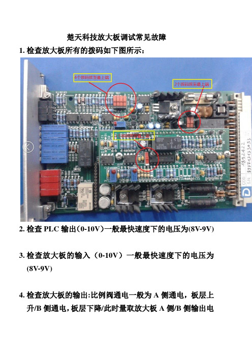
楚天科技放大板调试常见故障1.检查放大板所有的拨码如下图所示:2.检查PLC输出(0-10V)一般最快速度下的电压为(8V-9V)3.检查放大板的输入(0-10V)一般最快速度下的电压为(8V-9V)4.检查放大板的输出:比例阀通电一般为A侧通电,板层上升/B侧通电,板层下降/此时量取放大板A侧/B侧输出电流是多少,电磁阀最大工作电流为1.88A,1V=1I 此时板层运动最快的时候测得的电压应为1.88V慢速一般取1.2-0.75-0.45-0V可变,根据PLC输入的电压及放大板的最大电流/偏置电流来相互调整。
5.上升太慢,可调整A侧最大电流得到一个满意速度为止,最大为1.88V。
可以用电压表一边测一边上升一边调整。
6.下降太慢,可调整B侧最大电流得到一个满意速度为止,最大为1.88V。
可以用电压表一边测一边下降一边调整。
7.加载模式下即(自动模式)时按上升按钮,(A侧通电)板层上升停止后上下窜动,此时应将B侧的最大电流往小调整直至板层停止。
加载模式下,按上升按钮,(A侧通电)使能信号停止板层不停止,继续上升,此时应把A 侧的最大电流往小调整,直至停止。
加载模式下下降调整与上升调整相反。
8.上升定位不精准,减速不明显,可调整A侧偏置电流得到一个满意值为止,可以用电压表一边测一边上升一边调整,一般以1圈为一个单位。
9.下降定位不精准,减速不明显,可调整B侧偏置电流得到一个满意值为止,可以用电压表一边测一边下降一边调整一般以1圈为一个单位。
10.备注:按上述方式操作的前提是PLC输出为电压(0-10V)A侧通电为板层上升,B侧通电为板层下降。
10.。

MAX20048EVKIT#Evaluates: MAX20048 MAX20048 Evaluation KitGeneral DescriptionThe MAX20048 evaluation kit (EV kit) is a fully assembled and tested application circuit for the MAX20048 current-mode buck-boost controller IC. The EV kit is designed to deliver up to 16A (max) input current with input voltages from 2V to 36V. The output-voltage accuracy is ±2% within the normal 9V to 18V operation input range and a ±3% accuracy in the 2V to 18V range. Voltage quality can be monitored by observing the PGOOD signal.The IC offers 5V fixed output voltage and a 4V to 25V OUT programmable range. Switching frequency is adjustable from 220kHz to 2.2MHz, which allows for small external components, reduced output ripple, and guarantees no AM interference. The IC automatically enters skip mode at light loads with low 55µA quiescent current at no load. The IC comes with a spread-spectrum frequency-modulation option designed to minimize EMI-radiated emissions and a SYNCOUT option that outputs 180° out-of-phase clock. Benefits and Features●2V to 36V Input Supply Range●Delivers Up to 16A Input Current●Enable Input●Frequency Synchronization Input●Voltage-Monitoring PGOOD Output●BIAS Voltage-Monitoring Test Point●Fully Assembled and Tested●Proven PCB LayoutOrdering Information appears at end of data sheet.Quick StartRequired Equipment●MAX20048 EV kit●2V to 36V, 20A power supply capable of providing20A at 2V input●Voltmeter●Electronic loadProcedureThe MAX20048 EV kit is fully assembled and tested. Follow the steps below to verify board operation:1)Verify that all jumpers are in their defaultpositions, as shown in Table 1.2)Connect the positive and negative terminals of thepower supply to IN and GND test pads, respectively.3)Set the power-supply voltage to 14V and 10A currentlimit.4)Connect the positive terminal of the voltmeter to OUTand the negative terminal to GND2.5)Turn on the power supply.6)Verify that OUT is approximately 12V.Additional Evaluation7)Connect the positive terminal of the electronic load toOUT and the negative terminal to GND2.8)Set the electronic load to 2A and turn on the load.9)Verify output voltage on the voltmeter is 12V ±2%.10)With the load still on, slowly reduce the input voltagefrom 14V to 8V. Verify output voltage on the voltmeter is 12V ±2%Table 1. Default Jumper SettingsJUMPER DEFAULT SHUNTPOSITION FUNCTIONS EN ON-Middle Buck-boost enabled PGOOD PU InstalledPGOOD pulls up toVBIAS when OUT isin regulationSYNC FPWM-Middle Forced-PWM modeClick here for production status of specific part numbers.Evaluates: MAX20048 MAX20048 Evaluation KitDetailed Description of HardwareThe MAX20048 EV kit provides a proven layout for the MAX20048 buck-boost controller IC. The IC accepts input voltage as high as 36V and can deliver high-load currents, with a 20A (max) input current in boost mode. The EV kit can handle an input-supply transient up to 40V. Various test points are included for evaluation. The EV kit comes installed with a 3mΩ current-sense resistor on the input (R1) and a 4mΩ sense resistor on the output (R2). This sets the input current limit to 16.67A and the runaway current limit to 18.75A. A higher current limit can be set by changing the sense resistors. An optional filter input (IN_FILTER) is provided to test designs with an additional input filter. The default EV kit comes with no filter installed, so input terminal IN must be used.External SynchronizationThe IC can operate in fixed-PWM (FPWM) mode or skip mode. The EV kit comes with a default jumper setting of FPWM. T o enable skip mode operation, change the jumper to Skip-Middle. The IC can be synchronized to an external clock by connecting the external clock between the middle and ground pins on the SYNC jumper. The IC is forced to operate in FPWM mode when SYNC is connected to a clock source.Output Monitoring (PGOOD)The EV kit provides a power-good output test point (PGOOD) to monitor the status of the buck output (OUT). PGOOD is an open-drain output and is high impedance when the output voltage is in regulation. PGOOD is low impedance when the output voltage drops below 92% (typ) of its nominal regulated voltage. To obtain a logic signal, pull up PGOOD to BIAS by installing a shunt on the PGOOD jumper.Evaluating Other VoltagesThe EV kit comes installed with the MAX20048ATGCA/ VY+ and is configured for 12V OUT at a 420kHz switching frequency set for 16A (max) input current in boost mode. For evaluating other configurations, refer to the Design Example table in the MAX20048 IC data sheet. Other IC options for spread spectrum/SYNCOUT can be installed as well.EMC PerformanceEV kit provides a proven layout that is compliant with CISPR-25 requirements for EMC testing. The default EV kit (12V OUT, 420kHz configuration, without spread spectrum) requires no additional filtering to meet the CISPR-25 EMC standards. The IC also comes with the spread-spectrum option, which can be ordered to improve EMC performance.Specifications Summary●V IN (min): 2V●V IN (max): 36V●V OUT: 12V●f SW: 420kHz●I OUT (max): 5A●Input Current: 16.67A peak current●Runaway Current: 18.75A peak current●SPS: Off●FSYNC: Jumper set to PWM (default)#Denotes RoHS-compliant.PART TYPEMAX20048EVKIT#12V Output/420kHz EV kit Ordering InformationEvaluates: MAX20048MAX20048 Evaluation Kit REF DES QTY MFG PART #MANUFACTURERDESCRIPTIONC1, C2, C33CGA6P3X7S1H106M TDK CAP CER 10UF 50V X7S 1210C41EEH-ZE1H680PPanasonic CAP ALUM POLY 68UF 20% 50V SMDC5, C6, C173CGA2B3X7R1H104M050BB TDK CAP CER 0.1UF 50V X7R 0402C71CGA4J1X7R1V475K125AE TDK CAP CER 4.7UF 35V X7R 0805C81CGA2B2X7R1E103K050BA TDK CAP CER 10000PF 25V X7R 0402C91C0402C101K4RACAUTOKEMET CAP CER SMD 0402 100PF 10% X7R 1L20----Do Not InstallC10, C11, C153CAA572X7R1V107M TDK CAP CER 100uF, 35V, 2220, X7R C12, C13, C143CGA3E3X7R1H474K080AE TDK CAP CER 0.47UF 50V X7R 0603C161CGA4J1X7R1V225M125ACTDK CAP CER 2.2UF 35V X7R 0805C18, C192----Do Not InstallD11BAT54AWFILMY ST MicroelectronicsDIODE ARRAY SCHOTTKY 40V SOT323L11XAL1060-222E Coilcraft Inductor, 2.2uHR11PMR18EZPFV3L00ROHM RES 0.003 OHM 1% 1W 1206R21PMR18EZPFV4L00ROHM RES 0.004 OHM 1% 1W 1206R31ERJ-2GEJ473X Panasonic RES SMD 47K OHM 5% 1/10W 0402R51ERA-2AEB7322X Panasonic RES SMD 73.2K OHM 5% 1/10W 0402R6, R102ERA-2AED103X Panasonic RES SMD 10K OHM 0.5% 1/16W 0402R11, R14, R15, R164ERJ-2GEJ2R0X Panasonic RES SMD 2 OHM 5% 1/10W 0402R7, R12, R133RC0402JR-070RL Yageo RES SMD 0 OHM JUMPER 1/16W 0402R81ERJ-2GEJ200X Panasonic RES SMD 20 OHM 5% 1/10W 0402R91ERA-2AEB8662X Panasonic RES SMD 86.6KOHM 0.1% 1/16W 0402R171RC0603JR-0710KLYageo RES SMD 10K OHM 5% 1/10W 0603R41----Do Not Install R18, R19, R20, R214----Do Not InstallU11MAX20048ATGA/VY+Maxim Integrated Automotive 40V, 55uA Iq, 2.2MHz, H-BridgeBuck-Boost ControllerQ1, Q2, Q3, Q44NVMFS5C460NLON Semiconductor MOSFET N-CH 40V 21A 78A 5DFN IN_FILTER, IN, OUT, GND,GND2, GND365020Keystone Electronics TEST POINT PC LOW PRO W/OUT BASE FBR, PGOOD, VCC 35012Keystone ElectronicsTEST POINT PC MULTI PURPOSE WHT ENABLE, SYNC2PEC03SAAN Sullins CONN HEADER .100 SINGL STR 3POS J41PEC02SAANSullinsCONN HEADER .100 SINGL STR 2POSMAX20048 EVKIT BOMMAX20048 EV Kit Bill of MaterialsEvaluates: MAX20048 MAX20048 Evaluation KitMAX20048 EV Kit SchematicMAX20048 EV Kit Component Placement Guide―TopEvaluates: MAX20048 MAX20048 Evaluation KitREVISION NUMBER REVISIONDATE DESCRIPTIONPAGESCHANGED07/18Initial release—Revision HistoryFor pricing, delivery, and ordering information, please contact Maxim Direct at 1-888-629-4642, or visit Maxim Integrated’s website at .MAX20048EVKIT#。
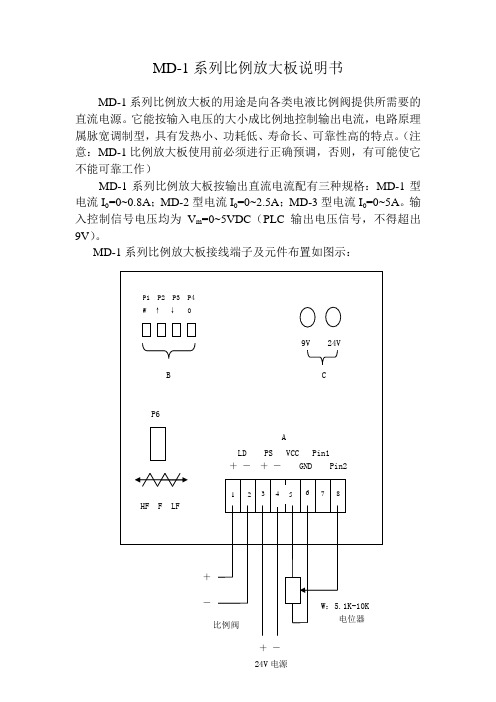
MD-1系列比例放大板说明书MD-1系列比例放大板的用途是向各类电液比例阀提供所需要的直流电源。
它能按输入电压的大小成比例地控制输出电流,电路原理属脉宽调制型,具有发热小、功耗低、寿命长、可靠性高的特点。
(注意:MD-1比例放大板使用前必须进行正确预调,否则,有可能使它不能可靠工作)MD-1系列比例放大板按输出直流电流配有三种规格:MD-1型电流I0=0~0.8A;MD-2型电流I0=0~2.5A;MD-3型电流I0=0~5A。
输入控制信号电压均为V m=0~5VDC(PLC输出电压信号,不得超出9V)。
MD-1系列比例放大板接线端子及元件布置如图示:图中A区为接线端子:PS+(3)—24VDC正输入端子;PS-(4)—24VDC负输入端子;LD+(1)—比例阀电磁铁绕组正端;LD-(2)—比例阀电磁铁绕组负端;V CC(5)—直流+9V输出端子(对GND),可作控制信号使用;GND(6)—控制信号的参考地;P in1(7)和P in2(8)—控制信号的输入端子(对GND)。
使用两位数并联数码盘调节输入信号时,P in1和P in2应分别接入;其它情况,可任意选用P in1和P in2 ,接线时应绝对避免GND端与PS一端相连,否则,将烧坏比例放大板。
图中B区位调整电位器:P1(M)—增益调整(用于满量程定标,逆时针减小,出厂为最大状态);P2(↑)—输出电流上升斜率调节(出厂最快状态,逆时针减慢);P3(↓)—输出电流下降斜率调节(出厂最快状态,逆时针减慢);P4(0)—输出电流初值调节(出厂为零电流状态)。
图中C区为显示二极管:二极管点亮显示DC24V供电及DC9V控制电源正常工作。
其预调方法有下列二种:1、电位器输入信号法¢1.1按上述布置图正确接线,通入24V电压(必须接入电流表)。
1.2将电位器W转至最小,调节电位器P4,可获得初始电流值。
1.3慢慢转动电位器W,使电流表读数为1A,再逆时针转动电位器P1,使电流表读数为0.8A。
![[说明]注塑机比例流量、压力的调校](https://img.taocdn.com/s1/m/3c8f930211661ed9ad51f01dc281e53a58025184.png)
[说明]注塑机比例流量、压力的调校[说明]注塑机比例流量、压力的调校比例流量、压力的调校1、比例阀与电子放大板比例流量阀和比例压力阀统称比例阀。
它有阀体和油摯线圈组成。
它的主要作用是通过油摯线圈受电的大小来控制阀的流量开放多少。
而油摯线圈受电和阀体流量开放程度是按一定比例线性关系而变化的。
当注塑机注塑预置叁数后,通过CPU中央处理器的处理和电子放大板的处理后,注塑机的注塑工作压力和流量就由比例阀控制。
具体可以用电箱旁的DPCA和DSCA电流表来显示比例线性关系。
具体叁数如下。
当S=00时,比例流量DSCA电流电流表显示200Ma;当S=99时,比例流量阀在DSCA表上显示680Ma当P=00时,比例压力阀在CPCA表上显示0mA;当P=99时,比例压力阀在DPCA表上显示800Ma。
而相对的压力表在15~145kg/CM2范围内呈现性变化。
DSCA电流表上和DPCA电流表上显示的电流叁数也就是比例流量、比例压力油摯阀线圈电压变化索取的。
它受控于电脑CPU中央处理器和电子放大板控制。
电子放大板输出电压控制比例流量、比例压力阀。
控制比例流量、比例压力阀的线圈吸合程度来控制油压和油流量。
2、比例阀与电脑CPU中央处理单元比例阀与电脑CPU中央处理单元是紧密相连,密切相连,共为一体,共同来完成注塑工作。
其运行过程应当为:叁数预置——>电脑处理——>电子放大板——>比例流量——>注塑各动作。
了解比例阀与电脑CPU中央处理单元的关系,对维修工作提供依据。
预置叁数使得数据进入电脑CPU中央处理单元,经过对叁数的运算和处理,将数据量通过D/A变换器转换成模拟量信号。
而该模拟量信号又经比例放大处理后,输出再通压力、流量最高控制和压力、流量最低限额控制4电位器进行控制调校,输出信号的幅值实际中应在0~3V范围内变化。
在维修过程中,一般调校好后才可以上机工作,不宜调节压力最高限额控制电位器,否则会改变工作点,给下一级控制带来困难。

Bosch Rexroth AG ,RC 30110,版本:2013-04目录特点 1订货代码 2功能2电路图/插脚分配,选件 T1 4电路图/插脚分配,选件 T5 5技术数据 6特性曲线7显示/调节元件,选件 T1 8显示/调节元件,选件 T5 9尺寸11项目规划/维护说明/附加信息11特点▶差分输入(±10 V)▶ 4 个可调用控制值输入(±10 V) ▶电流输入(4 … 20 mA)▶通过 24 V 输入或跳线改变内部控制值信号极性▶通过相位识别(24 V 输入)或斜坡时间调用(24 V 输入)选择斜坡时间(选件 T5) ▶通过跳线选择斜坡时间范围▶通过可分别调节的阶跃电平和最大值进行特性曲线校正 ▶选通输入 ▶"斜坡开/关"输入 ▶"准备就绪"输出信号▶可通断的测量插口(选项 T5) ▶电源反向极性保护▶电源带直流/直流转换器, 不改变零电位H7299用于比例方向阀和比例压力阀的阀放大器▶组件系列 2X ▶模拟,欧洲板卡格式 ▶适用于控制比例方向阀:– 4WRA 6…-2X,4WRA 10…-2X,– 4WRZ…-7X,以及比例压力阀:– 3DREP 6..2XRC 30110版本:2013-04替代对象:05.12型号 VT-VSPA2-1注意事项:使用 VT-VSPA2-1-2X 放大器板卡作为 VT 3000-3X,VT 3006-3X,VT 3013-3X,VT 3014-3X,VT 3017-3X,VT 3018-3X,VT 3026-3X,VT-VSPA2-1-1X/… 或VT-VSPA2-50-1X/… 的替代品时,确保遵守符合 30110-Z 附加信息的配置和设置信息。
2/12VT-VSPA2-1 | 阀放大器Bosch Rexroth AG ,RC 30110,版本:2013-04订货代码01用于比例方向阀和比例压力阀的阀放大器,模拟,欧洲板卡格式VT-VSPA202用于控制比例方向阀 4WRA 6…-2X,4WRA 10…-2X 和 4WRZ…-7X 以及比例压力阀 3DREP 6..2X 103组件系列 20 至 29(20 至 29:技术数据和插脚分配不变)2X 04型号:标准V005选项:对于一个斜坡时间T1选项:对于五个斜坡时间T506明文形式的更多详细信息*010203040506VT-VSPA2–1–2X /V0//*功能开放式板卡插槽 VT 3002-1-2X/48F(请参阅样本 29928)附件供电设备 [1]放大器板卡随附了带接通电流限制器的供电设备。

1/8模拟放大器类型 VT-VRPA1-50 至 VT-VRPA1-521X 系列RC 30117/07.06替代对象:05.06目录内容 页码特点 1订货代码 2功能说明2 - 3电路框图/插脚分配 4技术数据 5 - 6单元尺寸 6指示/调节元件7工程/维护注意事项/补充信息8特点– 适用于控制带有电气位置反馈的先导式比例流量控制阀(节流阀),类型 FE(规格 16 和 25)和 FES(规格 25 至 63)– 在插头方面,兼容放大器类型 VT 5011,VT 5012 和 VT 5062 至 VT 5066(视阀类型和规格而定)– 带可提高零电位的供电设备– 控制值信号输入:• 0 至 +6 V;0 至 +9 V;0 至 +10 V • 0 至 20 mA;4 至 20 mA(跳线)– 前面板上用于实现零电位和振幅衰减的电位计调节 – 斜坡时间的测量插口– 选通输入和"斜坡关闭"输入– 用于将最大斜坡时间从 0.02 s 更改至 5 s 或从 0.2 s 更改至 50 s 的跳线– 用于调整阀类型和规格的跳线– 控制值(0 至 +6 V)和实际值(0 至 –6 V)的输出– LED 指示灯"准备就绪"– 反向极性保护H6197_d订货代码用于带电气位置反馈的比例阀的模拟放大器,带1 个输出级用于以下比例流量控制阀(节流阀)的放大器:– 类型 FE 16,FE 25 和 FES 25(各类型均自系列 2X 起) = 50– 类型 FES 32 和 FES 40(各类型均自系列 3X 起) = 51– 类型 FES 50 和 FES 63(各类型均自系列 3X 起) = 52明文形式的更多详细信息1X =10 至 19 系列(10 至 19:技术数据和插脚分配不变)VT-VRPA11X*订购用于机架安装的 VT 5011,VT 5012 和 VT 5062 至 VT 5066 放大器备件时,盲板 4TE/3HE 必须单独订购。
比例放大板实验调试报告VT-3013(3014)BS30型一、实验目的:1、DA模块接线。
2、比例放大板接线。
3、比例放大板输出电流检测。
(1)电流表或万用表接电阻(40W,20Ω)串接进电路直接测输出电流。
注:比例放大板是恒流源,必须串接电阻,否则会烧坏万用表。
(2)测量DA模块差动电压(16A,16C)再换算。
(3)测试孔BU2,BU3用直流电压档测,约等于电流值。
4、组态。
5、电位器及电位器型传感器调整比例阀板电流。
6、拉绳传感器及AD模块接线。
二、实验原理:1、D/A模块:模拟信号与数字信号的转换模块。
(AD模块将模拟信号转成数字信号,DA模块是将数字信号转成模拟信号)2、放大板工作原理就是几级放大,把弱的模拟信号放大几百倍后再输出,是按比例放大的,就是输入信号×放大倍数=输出信号。
3、PLC加DA转换模块,就是把PLC内的数字量转化成模拟量,变成0-10V电压,而比例阀是可以接受模拟的电压电流信号的,但是与PLC的DA模块输出的电压、电流信号可能不一致,所以需要一个中间放大环节,把PLC的D/A模块输出的信号放大成比例阀能接受的电压或电流信号。
4、实验台系统采用24v开关电源供电,根据比例阀的输出特性,选择电流表、功率表等作为测量工具。
使用PC机作为上位机,读取模拟量模块数值、编写调试程序。
三、实验器材四、具体接线步骤:(一)比例放大板接线:(1)比例电磁铁线圈A两端分别接30A和24A;两端可以互换。
(30a,+V)比例电磁铁线圈B两端分别接28A和22A;两端可以互换。
(28a,+V)(2)比例控制器需直流24V供电电源正极接32A(或32C);电源负极接26A(或26C);本控制器需单独使用电源,不能与其他用电元件共用一个电源。
(二)可编程控制器(PLC)、DA模块接线函数发生器(此处为DA模块)等给出±10V差动电压从16A,16C两端输入正电压控制电磁铁B,负电压控制电磁铁A。
比例放大板调试指导
T he Debugging Roution of ATOS proportional amplifier
该调试说明以盘刹使用的放大板为例.对于猫头扭矩限制使用的放大板,调节方法相同.
1.调试工具:
数字式万用表一只,一字螺丝刀一把.
2.最大输出电压的调节
a)将万用表调整到直流电压检测挡(DC),再把万用表正极表笔接
触到a26号端子,负极表笔接触到a28号端子,如图
b)观察万用表上是否有电压值,如果有,用螺丝刀调节放大板S1
死区调整旋钮,使得万用表上显示电压为0V。
c)拉动盘刹制动手柄到最大位置, 观察万用表上电压值.通过S1
调节增益调整旋钮使得万用表读数为10VDC.
3.最大输出电流调节
a)将万用表调整到直流电压检测挡,再把万用表正极表笔插
入到前面板的电流输出正极孔内,负极表笔插入到负
极孔内.
b)拉动盘刹制动手柄到最大位置, 观察万用表上电压值.通过
调节S1增益调整旋钮使得万用表读数为2.1V.此时对
应放大板最大输出电流2.1A.
3.上升及下降斜坡设定(默认设置即可).
宏天公司技术部
2011.4.19。
Proportional T echnology1/8” and 1/4” portedCatalogue No. PDE2534TCUK-ab Issue 02/05Proportional Regulator ER08Proportional technology05-01/euro_pneumatic2Man-machine interfaceHigh visibility LED display Easy to read characters All controls on the same faceTotal flexibilityUser friendly and easily accessible softwareOne basic unit suits all customer requirementsSpecial applicationsFood version:Clean line design Suitable for washdownCompact & light weightSmall envelopeLight weight (P3PH = 285 gram)Flexible mounting optionsStand-aloneFoot bracket mounting DIN-rail mountingProportional technology05-01/euro_pneumatic3Applications for this innovative product in the Automotive industry can be seen in major manufacturers ‘body-in-white’ lines.The control of clamping and welding forces during panel assembly is an ideal application,also accurate control in paint dipping and spraying can be achievedGeneric IndustriesProportional technology05-01/euro_pneumatic4Why proportional technology ?The difference between open or closed circuit controlStandard pressure regulators, designed as part of our FRL series go a long way towards meeting our customersneeds. In most cases these regulators work well in general pneumatic and automation applications. However,sometimes the application calls for more precise pressure control. The effects of time, cycling, input, back pressure or pressure and flow variation can all cause inconsistencies in pneumatic systems. Our newProportional Regulators are designed to eliminate those inconsistencies.Open Control CircuitIn a normal pressure regulated control system, the inlet pressure (p1) is converted into the output pressure (p2) by the regulator. The set pressure (set value) is usuallymanually set by adjusting the control knob and in normal circumstances the regulator maintains the output pressure (actual value).No facility for monitoring the output pressure is provided and there is consequently no way of checking that the set value and the actual value are the same. Also, no account is taken of external influences such as air consumption by the system, which can drastically alter the actual value.Closed Loop Control CircuitThe input signal (set value) is converted into the output value (actual value) - as in control systems but this output value is continuously measured and compared with the input signal. If they are different, the regulation unitintervenes and adjusts the output value to correspond to the set value.Proportional Pressure RegulatorsThe new ER08 provides all the advantages of a closed circuit regulated system. When a set value is defined via the input signal (e.g. 0-10V), the pressure regulator sets the corresponding output pressure (e.g. 0-10 bar). At the same time the integrated pressure sensor measures the actual pressure at the unit’s outlet (actual value).If the electronic regulation system finds that the actual value has deviated from the set value, it immediately corrects the actual value. This is a continuous process ensuring fast, accurate pressure regulation.Typical application in automotive body inwhite welding pressure controlProportional technology05-01/euro_pneumatic5Order KeyPopular OptionsDIN railFoot bracketMounting OptionsProportional technology05-01/euro_pneumatic6Technical Information PneumaticsWorking mediumCompressed air or inert gasses, filtered to min. 40µ,lubricated or non-lubricated, dried or un-dried, pressure dewpoint 3-5o C.Supply pressurePrimary (input pressure):10,5 bar:0 - 10 bar output range 7,5 bar:0 - 7 bar output range 2,5 bar:0 - 2 bar output range (others on request)Pressure control rangeAvailable in three pressure ranges, 0-2 bar, 0-7 bar or 0-10bar. Other ranges on request. Pressure range can bechanged through the software at all times. (parameter 19)Burst pressure of sensor 2 x F .S.*Air consumptionNo consumption in stable regulated situation.DisplayThe regulator is provided with a digital display, indicating the output pressure, either in BAR or PSI.The factory setting is as indicated on the label, can be changed through to software at all times (parameter 14).ElectronicsSupply voltage 24 VDC +/- 10%Current consumptionMax. 200 mA with unloaded signal outputsControl signalsThe electronic pressure regulator can be externally controlled through an analogue control signal of either 0-10V or 4-20mA. (Digital control on request).Output signalsAs soon as the output pressure is within the signal band a signal is given of 24V DC, PNP Ri = 1 K ohm Outside the signal band this connection is 0V.ConnectionsCentral M12 connector 4-poleThe electrical connections are as follows:Pin no.FunctionColour 124V supplybrown 20-10V control signal Ri = 100k white 30V (GND)supplyblue 424Valarm output signalblack*F.S. = Full scale = chosen max. output pressure = 100% pressure control range.SchematicProportional technology05-01/euro_pneumatic7Technical InformationDead bandThe dead band is preset at 1,1% F .S.*AccuracyHysteresis is equal to the dead band setting (1,1% F.S.*)Linearity: = < 0,3% F.S.*Signal bandThe signal band is preset at 5% F .S.*Proportional bandThe proportional band is preset at 10% F .S.*Fail safe operationAfter interrupting the power supply the present output pressure is maintained at approximately the same level.After switching on the power supply again the pressure can be adjusted immediately by giving a new control signal.Full exhaustComplete exhaust of the regulator is obtained at 1% of F.S.*Temperature range 0o C up to +50o C Degree of protection IP 65timea = proportional effectpressurerequiredpressure 1required pressure 2control signaldead bandsignal band proportional bandαRegulation characteristics*F.S. = Full scale = chosen max. output pressure = 100% pressure control range.EU conformity CE: standardEMC: according to directive 89/336/EECThe new pressure regulator is in accordance with:EN 61000-6-1:2001EN 61000-6-2:2001EN 61000-6-3:2001EN 61000-6-4:2001These standards ensure that this unit meets the highest level of EMC protection.Mounting positionPreferably vertically, with the cable gland on top.Air consumptionUnder normal conditions and in steady state there is no air consumption.MaterialsParts in contact with the working medium:• magnet core: steel• solenoid valve poppet: FPM • core housing: brass• solenoid valve housing: Techno polymer • regulator housing: Techno polymer • valve: Polyurethane• seats and auxiliary piston: Delrin, Brass • remaining seals: NBR • port connectionsstandard version : brass food : stainless steelProportional technology05-01/euro_pneumatic8Flow characteristicsInput protectionThe unit has built-in protection against failure and burnout resulting from incorrect input value, typically:The 24v DC supply is incorrectly connected to the setpoint input, the display will show ‘OL ’, as an overload indication.The unit will need to be rewired and when correctly connected will operate normally.The overload indicator ‘OL ’ will also appear should the wrong input value be applied or the wrong input value be programmed: (0 - 10v instead of 4 - 20mA or conversely 4 - 20mA rather than 0 - 10v). To correct this a different set point value should be input or the unit reprogrammed to correct the set point value acceptance. (via parameter 4).Response timesTo fill volume of 100cm ³, connected to the outlet of the regulator:Pressure increase from 2 to 4 bar » 30 msecs Pressure increase from 1 to 6 bar »120 msecs Pressure decrease from 4 to 2 bar » 60 msecs Pressure decrease from 6 to 1 bar »160 msecsSettingsThe regulator is pre-set at the factory. If required,adjustments can be made.Advanced functionalityPilot valve protectionWhen the required output pressure can not be achieved because of a lack of input pressure the unit will open fully and will display NoP. Approximately every 10 seconds the unit will retry . The output pressure will then be approximately equal to the inlet pressure. As soon as the input pressure is back on the required level, the normal control function follows.Safety exhaustShould the control signal fall below 0,1 volts the valve will automatically dump downstream system pressure .Fail safeWhen the supply voltage drops below 19VDC, theelectronic control reverts to the fail safe mode. The last known output pressure is maintained at approximately the same level depending upon air consumption. The digital display indicates the last known pressure setting.When the supply voltage is reinstated to the correct level,the valve moves from the fail safe mode and the output pressure immediately follows the control signalrequirement. The display indicates the actual output pressure.Proportional technology05-01/euro_pneumatic9Changeable SettingStandard Description Unit Action Resultuservalueparameters*03green key Back to factory settings Back to normal settings401mA Set setpoint input to mA 0(4)-20mA, (P29)1VSet setpoint input to volt 0-10V 600Alarm output Set output to digital alarm output 24V= in band 1Analog outputSet output to analogue output 0-10V~P_out9-+ adjust display value1250 to 250100x 10 mbar Set proporitonal band 0,5 to 2,5 bar 13 2 to 4015x 10mbarSet deadband area20 to 400 mbar140bar set pressure indicating value displayed in bar 1psivalue displayed in psi 180 to 2000x 10 mbar Set preset pressure (x10 mBar)0 to 2 bar 190 to 100100% F .S.Pressure correction 0 to P-max 200Custom set Set behaviour controlP 12,13, 211Fastest 2Fast 33Normal 4Slow 5Slowest21510Set proportional effect fastest regulation to 100slowest regulation 39--Software versionthree digitsoftware version*Other parameter settings are available. Consult factory.How to change parametersPressing the Accept key for more than 3 seconds, willactivate parameter change mode. The user can then select the parameters by pressing up or down key. (display will show Pxx). When parameter number is correct, pressing accept again will enter parameter number.(display will show parameter value).Pressing the up or down key will change the parameter itself. (display will flash indicating parameter editing mode).Pressing the accept key will accept the new parameter value. (all digits will flash whilst being accepted).After releasing all keys , the next parameter number will be presented on the display. (you may step to the nextparameter). When no key is pressed, after 3 seconds the display will show the actual output pressure.Manual modeWhen keys DOWN and UP are pressed during startup,(connecting to the 24V power supply) manual mode is activated. This means that the user is able to in/decrease the output pressure of the P3H, by pressing the UP or DOWN key. During this action the display will blink,indicating that the manual mode is activated.Back to factory setting After start up. (Power is on)Parameter 0 = 3 (green_key function)Entering this value in parameter 0 will store the calibrated factory data into the working parameters. (Default calibration data is used)Behaviour controlThe regulation speed of the pressure regulator can be modified by means of one parameter. (P 20)The value in this parameter has a range from 0-5, a higher value means slower regulation speed but it will be more accurate. When the value 0 is entered, you are able to create your own custom settings true parameters 12,13and 21.Preset pressureIf there is a need to keep secondary side pressurized at all times. The pre-set pressure can be set through parameter 18. (Note: value is set in mbar.)Proportional technology05-01/euro_pneumatic10SALE CONDITIONSThe items described in this document are available for sale by Parker Hannifin Corporation, its subsidiaries or its authorized distributors. Any sale contract entered into by Parker will be governed by the provisions stated in Parker’s standard terms and conditions of sale (copy available upon request).Troubleshooting guideProblemDisplay will not light up Unit will not, or not correctly respond to given setpointDisplay shows NoP.Unit behaviour is not considered normalDesired pressure can not be reachedSecondary side stays pressurizedDisplay shows unrealistic valueUnit response time too slow or too quickUnit gives too much overshoot Unit is adjusting/regulating constantlyCan not enter software through touchpadDisplay indicates ‘OL ’Any other problemPossible ReasonNo 24 volts power supply Wrong current applied ( I.e. Volt instead of mA or mA instead of VoltSetpoint signal is not stable enoughUnit detects that required output pressure is higher than the supplied pressureNo inlet pressure at allFaulty settings made in the software Setpoint value to lowPre-set pressure limit has been changed to a lower max. outlet pressure Supply pressure is to lowSetpoint value is higher than 0,1 Volt Pre-set pressure has been enabled to a certain pressureDisplay maybe configured in the wrong value ( bar instead of psi)Volume behind the unit is either too big or too smallRelation between volume and response time is out of balanceAirleakage in the system behind the unit Constant changing volume behind the unit“Deadband “area is set too smallUnit is currently working/processing Activating time is too shortWiring not according to diagram (24 volt connected on the setpoint connection pin)Wrong setpoint value given in relation to programmed setpoint value acceptanceSolutionCheck if the wiring is connected according to the schematic wiring diagramChange setpoint current or re configure the setpoint current through the software by changing parameter 4Check wiring if the setpoint signal lead isconnected to the right pin within the male M12connector ( should be pin 2)Stabilize setpoint signal inputAdjust the inlet pressure to a higher value,preferably 0,5 bar higher than requested output pressureG ive lower setpoint value which corresponds to a output pressure lower than the inlet pressureConnect port 1 to the supply pressure Reset the unit to factory settings by using the green key function under parameter 0Increase setpoint valueChange max. outlet pressure back to required pressure by changing parameter 19Increase supply pressureLower your setpoint value, preferably to 0 Volts Reset parameter 18 to 0Check through parameter 14, if the display value is set on either psi or bar, if necessary change it to the required settingAdjust the regulating speed of the unit through parameter 20Adjust response time to a higher value through parameter 20, to acheive more accurate behaviour Resolve leakageUnit needs to regulate to keep required pressure at the same levelTry to minimize the volume changesEnlarge deadband setting through parameter 13 in the software ( parameter 20 has to be set to 0 before changing parameter 13)Make sure that the unit is in steady state while activating the softwareHold the accept button for at least 3 seconds Rewire so that on the setpoint connection pin will be either 0-10v or 4-20mAChange over setpoint value to either V or mA orReprogramme the unit to the correct setpoint value via parameter 4Please consult factoryProportional technology05-01/euro_pneumatic11Side exhaust versionDimensional drawingsBottom exhaust versionParker Hannifin plc Wilkerson Service Centre Walkmill Lane, Bridgtown,Cannock, Staffs. WS11 0LR United Kingdom Tel:01543 456000Fax:01543 456001Web:/euro_pneumaticWilkerson Operations 1201 West Mansfield Avenue Englewood, CO 80110 USA Tel:(303) 761-7601Fax:(303) 783-2300Web: We reserve the right to make alterations without prior notification.Edition 04.04WILKERSON OPERA TIONSREGISTERED TO ISO 9001CERTIFICATE NO. A2192FM21121Certificate No。