creo4.0-新功能graphics-rendering
- 格式:pdf
- 大小:687.76 KB
- 文档页数:4
资讯· 4 ·IMcadcam@IMCHINA@投稿邮箱Gartner:2016年第四季度全球智能手机销量增长7%近日,信息技术研究和顾问公司Gartner 表示,2016年第四季度全球智能手机对终端用户销售量(以下简称智能手机销售量)总计4.32亿部,较2015年同期增长了7%。
苹果(Apple)在2016年第四季度销售7703.89万部智能手机,超越三星(Samsung)7678.26万部的销量,拿下全球智能手机厂商销量第一名。
2016年全年智能手机销售量总计15亿部,较2015年增加5%。
在智能手机操作系统市场方面,Google 的Android 系统扩大了领先优势,在2016年第四季度整体市场占有率达82%。
就2016年全年来看,Android 市场占有率也增长了3.2个百分点,达到84.8%,而且是各操作系统中唯一市场占有率较前一年有所增长的系统。
Anshul Gupta 指出:“Google 推出Pixel 手机后,顶级Android 智能手机更具竞争力,而(诺基亚的)HMD 手机重返基本款(中阶)智能手机领域,则将近一步提升该款操作系统在新兴市场的竞争力。
”IBM推出面向认知工作负载的全闪存存储器日前,IBM 宣布推出专为大中型企业而设计的闪存存储解决方案,以满足其高可用性、连续运行和性能方面的需求。
这些全闪存存储解决方案将提供大中型企业所需的速度及可靠性,处理企业资源规划(ERP)、金融交易以及认知应用(如机器学习和自然语言处理)等工作负载。
此次宣布推出的全闪存存储解决方案旨在支持那些认知工作负载,这些负载能帮客户发现趋势和模式,从而提升决策能力、改进客户服务并提高投资回报率。
IBM 将继续推动闪存解决方案突破设计界限,以提供卓越性能来管理最苛刻的工作负载,例如,那些需要“六个九可用性”(即99.9999%连续运行时间)的工作负载。
通过深入集成来自IBM 存储和IBM z Systems 方面的能力,这些全新解决方案已经将面向大中型企业的数据保护、远程复制和优化功能嵌入其中。

新增功能:Creo Parametric4.0日期代码F000及更高版本4详细绘图(细节化)详细绘图中更直观的基准特征符号创建和编辑工作流 (34)详细绘图中基准特征符号的自动命名 (35)在详细绘图中指定基准特征符号附近的附加文本 (35)将弯头添加到详细绘图中的基准特征符号 (36)详细绘图中更直观的基准目标创建和编辑工作流 (37)在详细绘图中指定基准目标的基准参考 (38)详细绘图中基准目标的基于标准语法检查 (39)详细绘图中的智能内建目标区域 (40)目标区域尺寸在详细绘图中可能位于符号外侧 (40)详细绘图中支持可移动基准目标注释 (41)详细绘图中基准目标的虚线指引线 (42)详细绘图中更直观的几何公差(GTOLS)创建和编辑工作流 (43)详细绘图中几何公差(GTOL)的灵活且符合标准基准参考 (44)详细绘图中几何公差(GTOL)的灵活公差值和基准规范 (44)详细绘图中几何公差的基于标准语法检查 (45)详细绘图中改进的复合几何公差(GTOL) (46)详细绘图中几何公差(GTOL)中的ISO GPS指示符支持 (47)详细绘图中更直观的尺寸创建和编辑工作流 (48)详细绘图中改进的尺寸原点支持 (48)详细绘图中改进的尺寸文本 (49)详细绘图中用于控制尺寸方向的更多选项 (50)详细绘图中对尺寸孤连接的改进 (51)详细绘图中对驱动尺寸修改的更多控制 (52)快速将图像添加至详细绘图 (52)快速替换绘图视图的模型 (53)详细绘图中的非线性剖面线样式 (54)详细绘图中符合标准的文本和符号字体 (55)详细绘图中通过多线程处理隐藏线移除计算 (56)33详细绘图中更直观的基准特征符号创建和编辑工作流用于创建和编辑基准特征符号的工作流更为直观。
用户界面位置:单击“注释”(Annotate)▶“基准特征符号”(Datum Feature Symbol)。
版本:Creo Parametric4.0优点和说明您可以观看演示此功能的视频。

Pro/ENGINEER Wildfire野火版4.0议程…..PTC简介Pro/ENGINEER Wildfire野火版4.0基本抱演示问题和回答Pro/ENGINEER 是业界首套参数化CAD 解决方案发布了Pro/ENGINEER率先在市场上推出参数化、基于全相关特征的实体建模技术以PMTC 首次公开上市公司成立发布了Windchill率先在市场上推出基于互联网的PLM 解决方案收购了ComputervisionPTC 客户超过20,000家《工业周刊》表彰Pro/ENGINEER 为“年度突出科技”PTC 客户超过25,000家快速启动摂软件包将PLM 实施时间缩短至数周发布了Windchill ProjectLink推出针对项目协作的纯互联网体系结构解决方案PTC 的产品开发体系(PDS )市场上唯一的一体化PLM 解决方案发布了WindchillPDMLink推出针对产品数据管理的纯互联网体系结构解决方案PTC 客户超过35,000家因ECAD 集成而收购了俄亥俄设计自动化公司推出全球产品开发(GPD )创新活动发布了按需即推PLM与IBM 建立了战略伙伴关系收购了ITEDO领先的2D 技术插图解决方案收购了Mathsoft工业标准工程计算解决方案Windchill XML 内容管理发布了Pro/ENGINEER Wildfire 野火版首套完全支持Web 服务的CAD 系统《工业周刊》再次表彰Pro/ENGINEER 为“年度突出科技”收购了NC Graphics一流的CAM 高速精密机加工解决方案重大里程碑收购了Arbortext动态发行领域的领先供应商因MPM 收购了Polyplan 科技公司,因鞋类和服装而收购了Aptavis 科技公司收购了LBS航空/航天与国防和民用航空ILS 解决方案的领先供应商为满足医疗器械品质体系管理需要而收购了NetRegulus打算收购CoCreateCAD 和PLM宏思达斯科技有限公司简介宏思达斯科技有限公司是专业致力于计算机软件销售、服务、实施为一体的专业性软件公司。

PROE野火版4.0,系统配置文...关于配置文件选项为配置文件输入所需的设置,可以预设环境选项和其它全局设置。
要设置配置文件选项,使用“选项”对话框(“实用工具”>“选项”)。
本帮助模块含有一个按字母顺序显示每一选项或相关选项组的配置选项列表:·配置选项名称。
·相关变量或值。
选项的缺省值显示为斜体。
·简单说明。
accuracy_lower_bound 数值(在1.0e-6和1.0e-4之间)输入一个精确值来覆盖缺省下限0.0001。
上限固定为0.01add_java_class_path <搜索路径>此选项涉及到有关JA V A环境变量CLASSPA TH的选项值,它用于查找J-Link程序中使用的类。
可在同一行上指定多个搜索路径,在UNIX中用“:”隔开,在WindowsNT中用“;”隔开。
设定此选项后,启动第一个J-Link应用程序时才会生效add_weld_mp yes, noyes - 系统在计算质量属性时,包括焊接。
no - 系统在计算质量属性时,排除焊缝。
allow_anatomic_features yes, no将此配置文件现象设置为yes,使得下列选项可用:“扭曲”菜单中:“局部拉伸”、“半径圆顶”、“截面圆盖”、“耳”、“唇”。
“实体”菜单中:“开槽”、“轴肩”、“凸缘”、“退刀槽”。
“基准”菜单中:“计算”。
allow_cycle_optimize yes, no在18.0以前的版本中,有一个孔加工序列参数,允许用户优化孔加工序列CL-数据的循环输出。
自版本18.0以来,该参数不再有效。
yes - 使该参数在序列中可见no - 该参数在序列中不可见allow_move_attach_in_dtl_move yes, no确定绘图模式中的“移动”和“移动附属”命令是(yes) 否(no) 一起执行allow_move_view_with_move yes, no设置为“yes”时,可以使用“绘图”模式中的“移动”命令,移动绘图视图。

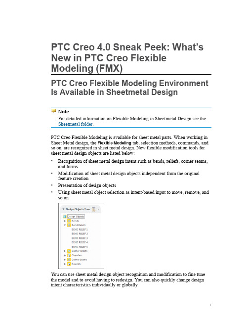
PTC Creo4.0Sneak Peek:What’s New in PTC Creo Flexible Modeling(FMX)PTC Creo Flexible Modeling Environment Is Available in Sheetmetal DesignNoteFor detailed information on Flexible Modeling in Sheetmetal Design see the Sheetmetal folder.PTC Creo Flexible Modeling is available for sheet metal parts.When working in Sheet Metal design,the Flexible Modeling tab,selection methods,commands,and so on,are recognized in sheet metal design.New flexible modification tools for sheet metal design objects are listed below:•Recognition of sheet metal design intent such as bends,reliefs,corner seams, and forms•Modification of sheet metal design objects independent from the original feature creation•Presentation of design objects•Using sheet metal object selection as intent-based input to move,remove,and so onYou can use sheet metal design object recognition and modification to fine tune the model and to avoid having to redesign.You can also quickly change design intent characteristics individually or globally.New Geometry Search Tool in PTC Creo Flexible ModelingUse this powerful Geometry Search tool to quickly find similar geometry or design objects as input for a simultaneous modification.You can create rules for searching geometry are described below:•Create a rule based on geometry or design-intent characteristics.•Derive rule parameters based on a seed selection.•Save or load rules for reuse.Examples of rules are listed below:•Select all holes with diameter d>mm and d<3mm•Select all rounds with radius r<1mm•Find all similar geometric shapes.When you open the Geometry Search tool from within another tool you can select to do one of the actions listed below:•Add as a selection—Search results are added to the selection.•Use as query in active feature—Search results are added as query that is saved to the reference collector to the tool from which you opened the Geometric Search tool.2D Box Selection Is Available in PTC Creo Flexible ModelingFor faster selection and higher design productivity,selection using the2D Box is available for most object-action workflows.This easy-to-use selection type supports left-to–right selection to select all objects in the box and right-to-left selection to select all objects touched by the box.Selection filters are also applied during the selection.NoteBox selection is not recommended for intent-based selection.Shape Selection Is Improved in PTC Creo Flexible ModelingThere is improved shape recognition for bosses and cuts.Through automatic detection of bleeding surfaces,more local shapes are found during selection.In addition shapes that are found are more seed independent.More intuitive results from shape selection improves ease of use.Mini Toolbar Is Available in PTC Creo Flexible ModelingThere is a PTC Creo mini tool bar is further optimized for PTC Creo Flexible Modeling.Within the Flexible Modeling environment,the mini toolbar shows an additional row with a set of selection options.These include various shape selection types and selection using geometry rules.When you right-click,the shortcut menus are also available.Whether using a shortcut menu or the mini toolbar,only those commands that apply to the current selection are available. When selecting geometry,context-sensitive commands are available at the pointer next to your selection.Faster and more intuitive access to commands makes work easier and more productive.Appearance is Maintained During PTC Creo Flexible Modeling OperationsColor and transparency is preserved for geometry modified in flexible modeling operations.New geometry is created in the part color where applicable and where possible.This saves time by minimizing time needed to reapply appearance settings.PTC Creo Flexible Modeling Tools Are EnhancedThe Move,Remove,Substitute,Attach,and Flexible Pattern tools in PTC Creo Flexible Modeling are enhanced as described in the table below:PTC Creo Direct Features Are Grouped in PTC Creo Flexible ModelingModifications that are made in PTC Creo Direct to a PTC Creo Parametric model, are represented as an automatically-created group of features,when loading the model into PTC Creo Parametric.©2016PTC Inc.The information contained herein is provided for informational use and is subject to change without notice.The only warranties for PTC products and services are set forth in the express warranty statements accompanying such products and services and nothing herein should be construed as constituting an additional warranty.PTC shall not be liable for technical or editorial errors or omissions contained herein.Important Copyright,Trademark,Patent,and Licensing Information:See the About Box,or copyright notice,of your PTC software.。
creo4.0怎么使⽤阴影法创建分型⾯?
分creo4.0中的分型⾯的设计⽅法有三种:⼀般分型⾯设计⽅法、阴影法、裙边法。
今天我们就来看看使⽤阴影法创建分型⾯的教程。
PTC CREO 4.0 M030 官⽅中⽂特别版(附破解⽂件+许可证+安装教程) 64位
类型:3D制作类
⼤⼩:5.86GB
语⾔:简体中⽂
时间:2017-09-26
查看详情
1、打开creo软件,创建⼀个模具类型⽂件(CP3.ASM).
2、⽤“组装参考模型”命令组装参考模型(CP3_REF_2.prt).
3、⽤“⾃动创建⼯件”创建坯料(CP3_WRK_2.PRT)。
4、单击模具功能选项卡分型⾯与模具体积块区域中的“分型⾯”。
5、单击“分型⾯”功能中的“曲⾯设计”右边下拉按钮,选择“阴影曲⾯”。
弹出“阴影曲⾯”对话框。
6、发现投影⽅向相反。
单击选择“阴影曲⾯”对话框中的”⽅向“,单击“阴影曲⾯”对话框中的⽅向”定义“。
7、弹出“菜单管理器”,单击选择坯料上表⾯。
8、单击“菜单管理器”中的“反向”。
单击“菜单管理器”中的“确定”。
9、单击“阴影曲⾯”对话框中的”确定“。
10、单击“分型⾯”功能中的”确定“按钮。
完成分型⾯创建。
以上就是creo4.0阴影法创建分型⾯的技巧,希望⼤家喜欢,请继续关注。
使用前须知Creo®:Creo Parametric、CreoSimulate、Creo Options Modeler、Creo Layout、Creo Direct4.0F000在线信息目录Copyright2016PTC,inc.。
4.0F000Creo®:Creo Parametric、Creo Simulate、Creo Options Modeler、Creo Layout、CreoDirect在线信息目录(续上页)2Creo Parametric,Creo Simulate,Creo Layout,Creo Options Modeler,Creo DirectCreo4.0可供安装Creo4.0是可扩展的套装软件,由数个具有互用性、大小合理的设计应用程序组成,便于企业内所有用户参与和推进产品设计过程。
借助这些应用程序,企业可以改进概念设计、详细设计以及校验和验证等过程,从而能够将更好的产品以更快的速度推向市场。
安装Creo4.0内含基于FlexNet Publisher11.14.0的PTC许可证服务器。
要运行Creo4.0,必须将PTC许可证服务器升级到11.14.0。
如果已针对Pro/ENGINEER®Wildfire®3.0或更高版本、Creo Elements/Direct5.0或更高版本、PTC Mathcad®14.0、PTC Arbortext®Isodraw®7.0或PTC Arbortext Editor6.0运行许可证服务器,PTC建议将PTC许可证服务器升级到11.14.0。
使用PTC安装助手为使Creo4.0应用程序的安装更顺利,可以使用DVD光盘上的PTC安装助手。
打开安装程序,输入销售订单号,安装助手会开始自动安装:•从PTC获取许可证文件•确定该许可证是浮动许可证还是固定许可证,然后根据需要安装许可证服务器•基于许可证文件中的授权提供可用产品的列表,并自动从下载和安装该软件。
过程: Creo 图形功能增强过程设置:为避免命名冲突,建议您先保存您的工作,然后单击“文件”(File)> “关闭”(Close)直到不显示任何模型,再单击“文件”(File) > “管理会话”(Manage Session) > “拭除未显示的”(Erase Not Displayed)。
单击“文件”(File)> “管理会话”(Manage Session)> “设置工作目录”(Set Working Directory),然后导航到PTCU\CreoParametric1\Enhancements\Graphics文件夹并单击“确定”(OK)单击“文件”(File) > “打开”(Open)然后双击GRAPHICS_ENHANCE3.PRT。
任务 1. 练习使用图形选项。
仅启用下列“基准显示”类型:。
请注意基准显示。
图1禁用“轴显示”(Axis Display) 、“点显示”(Point Display) 与“坐标系显示”(Csys Display) 。
图2在功能区中,选择“视图”(View)选项卡。
从“显示”(Show) 组中启用“平面标记显示”(Plane Tag Display) 。
图3禁用“平面标记显示”(Plane Tag Display) 。
在图形窗口中,将光标置于基准平面FRONT 上。
图4在“图形中”工具栏中禁用“平面显示”(Plane Display) 。
图5在“图形中”工具栏中,从“显示样式”(Display Style) 类型下拉菜单中选择“利用边着色”(Shading With Edges) 。
图6编辑“拉伸1”(Extrude 1)的定义。
在操控板中,单击“曲面”(Surface) 。
单击“完成特征”(Complete Feature) 。
单击背景,取消选择所有几何。
图7在“图形中”工具栏中,从“显示样式”(Display Style) 类型下拉菜单中选择“着色”(Shading) 。
PTC Creo4.0Sneak Peek:What’s New in Graphics and Rendering? Line Style Display
In collaboration with NVIDIA there is support in PTC Creo Parametric4.0for new GPU libraries for the display of line styles as described below:
•The overall quality of all lines styles is improved.
•Disconnected line sections when defining a thick line are addressed.
•The pattern flow issues visible in earlier releases of PTC Creo Parametric are resolved.
The new GPU supported line styles are available by default,however,you can use the configuration and detail options described below to make further adjustments:•force_cpu_style_rendering(configuration option)—Forces the previous CPU line style in the current session for all parts,assemblies,and drawings.
•pre_creo4_dwg_use_cpu_rendering(configuration option)—Forces CPU line style display on a given machine for drawings created in a release prior to PTC Creo Parametric4.0.
•pre_creo4_dwg_use_cpu_rendering(Detail option)—Updates the drawing so that it always uses CPU line style on all machines.
Model View Dialog Box
There is a single dialog box to access saved orientation states for a model,create new orientation states,or to modify the perspective settings.To open the View dialog box click View▶Saved Orientations▶Reorient.
Appearance State in View Manager
You can define different appearance states for your model in the View Manager from the Appearance tab.You can define different color combinations for specific use cases easily,without compromising your design.
Updated In-graphics Toolbar for General Rendering
For general rendering,the following commands are added to the In-graphics toolbar for easy access:
•Ambient occlusion
•Scene Background
The Render tab is not available in PTC Creo Parametric4.0.The core components from this tab,Scenes,Appearances,and Perspective View are in the View and Model tabs.
Advanced Rendering
A new rendering mode replaces the former Advanced Rendering Extension.The new application is accessible from the Applications tab in PTC Creo Parametric. You can switch between rendering and modeling without exiting the rendering application.Real-Time Raytracing powered by Luxion Keyshot,is provided.You can use the existing scenes and appearances applied to your design,such as lights, High Dynamic Range Image(HDRI)environment,and textures,and create a screen shot or output a fully rendered image.If you have an existing license of Keyshot,you can easily export your PTC Creo data to standalone Keyshot.
As you interact with your model,improved realistic rendering updates automatically.Existing Advanced Rendering Extension customers receive this solution at no extra cost.
©2016PTC Inc.The information contained herein is provided for informational use and is subject to change without notice.The only warranties for PTC products and services are set forth in the express warranty statements accompanying such products and services and nothing herein should be construed as constituting an additional warranty.PTC shall not be liable for technical or editorial errors or omissions contained herein.Important Copyright,Trademark,Patent,and Licensing Information:See the About Box,or copyright notice,of your PTC software.。