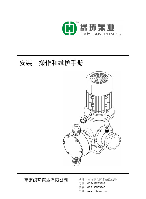
greenpro水泵说明书
- 格式:doc
- 大小:290.05 KB
- 文档页数:3

水泵安装、使用、维护说明书Type NG slurry PumpINST ALL TION, OPERA TION, MAINTENANCEMANUAL一、水泵的安装Pump installation水泵的安装Pump installation1、水泵安装准备工作1. The preparation work for pump installation.(1)检查水泵和电机,确知在运输和装卸过程中没有损伤。
Check the pump and motor, ensure there were no damage during the transportation and load or unload.(2)检查工具和起重机械,并检查机器的基础。
Check the tools and lifting equipment and also the basement of machine. (3)检查配套提供的压力表及表座。
Check the manometer and gauge stand of affiliated equipments2、水泵安装顺序Pump installation order(1)整套泵运抵现场时,都已装好电机;校平底座时,可不必卸下水泵和电机。
The motor have been installed when a whole set of pump arrived scene. When collate the basement, no need to demount the pump and motor.(2)在水泥基础上安装水泵时,基础平面应用水平找平,待基础水泥凝固后将泵安装在基础上,并用水平仪检查水平情况,如不平,应用垫铁调正,直到水平为止,然后通过灌浆孔由混凝土浇灌底座和地脚螺栓孔眼。
When install pump on the cement base, regulate the foundation flat by the standard. Check the condition of standard by thegradienter, if not flat, regulate it by the parallels until horizontal, use concrete to irrigate basement and foundation bolt hole by the grout hole. (3)水泥干固后,检查底座和地脚螺栓是否松动,合适后拧紧地脚螺栓的螺母,最后再检查一下整台机组的水平度,稍有不平时,可用斜铁找平。

ENTERALITE INFINITY PUMPInstructions for useKey points:1. Wash your hands with antibacterial soap before handling yourfeeding tube and supplies.2. If you have more than one catheter (example: feeding tube and I.V.),always double check to make sure you are infusing your formula intothe feeding tube and not into the I.V. line.3. Use a new Infinity feeding set each day.You may save your last feeding bag and reuse it for one additional day if youhave not received your delivery yet. Please contact HomeMed 3-4 days inadvance if you think you are going to run out of feeding bags.4.In case of a pump failure or power outage, refer to page 12 forinstructions.5. Store supplies and formula in a dry, clean area.6. Do not use supplies if: the seal is broken, the package is torn, or theinside or outside of the package is wet.7. Check your formula for expiration dates. Do not use formula if theexpiration date has passed. See page 5 for instructions on howmuch formula you can add to the bag each time you fill.8. Clean your pump weekly to avoid frequent errors (see page 7).9. Keep your pump plugged into the wall as much as possible.10. Unless otherwise directed, never mix your medications in with theformula. Medicine that needs to be put in your feeding tube shouldbe given separately with a syringe.How to use the Enteralite Infinity PumpIf you view the DVD provided by Zevex on how to use the Infinity pump, you willnotice some differences in our instructions below. We have designed theseinstructions to make setting up the pump as easy as possible.Step 1: Prepare the feeding seta. Place your feeding set on a clean surface.b. Prepare your formula as shown to you by a clinician.Note: If you blenderize your formula, let the mixture stand for ten to fifteenminutes before adding to the feeding set. This will decrease the chance of an alarm due to air in the tubing.c. Open the plastic cap of the feeding set and pour the formulainto the bag. Ask your nutritionist how much formula to add tothe feeding bag at a time. Formula can spoil if it hangs in thebag too long.d. Remove the excess air from the bag by squeezing the formulato the top of the plastic rim before closing the plastic cap.e. Remove the plastic protector from the end of the feeding set.f.Hang the bag on the I.V. pole so the bottom of the bag just above the pump. Step 2: Attaching the feeding set to the pumpa. Press the tab on the front of the pump door and lift up the door.b. To load the tubing into the pump, hold the cassette so that the clear plasticportion faces toward you and the loop of tubing is to the left (Figure 1). Loop the blue tubing around the wheel of the pump and stretch it slightly to the right(Figure 2). The plastic portion should drop into place.c. Close the lid by pressing the tabin until the latch clicks into place.Figure 1Figure 2Step 3: Priming the tubing Arraya. The feeding set must be primed with formula beforeconnecting it to the feeding tube.b. Press and hold the ON/OFF button for 2 seconds. Thepump will beep and run through a short self-test.c. Press and hold the PRIME key until the formula reaches the end of the red tip onthe feeding set. (The DVD that comes with the pump shows how to manuallyprime the feeding set although we have found this to be more difficult.)Step 4: Programming the pumpa. When you turn on the pump, it should be at the RATE screen. The word “RATE”should be displayed in the lower left corner of the screen. If not, press theRATE/DOSE key until “RATE” appears. Then press the + key until the desired rate is shown on the screen. The rate is the speed at which the formula isinfused (mL/hour). This is different than dose.b. Press the RATE/DOSE key to display DOSE in the lower left corner of thescreen. It should read INF. If INF is not displayed, then press and hold the + key until INF appears on the screen. (INF will appear on the screen after the dosereaches 3000.) INF stands for “infuse” which allows the pump to deliver theentire amount of formula that was put in the bag.c. You will not be using the FEED INTERVAL function and it should always be setto NONE. Press the FEED INT key, and then press the CLEAR key. The screen will read NONE.d. The VOL/TOTAL key keeps track of how much formula has been delivered. It isnot necessary to use this key since you are not setting a dose. If your push thisbutton, you can press RATE/DOSE to return to the RATE screen.Continues on next page…Step 5: Run the pumpa. Connect the red tip of the feeding set to the patient’s feeding tube.b. Press the RUN/PAUSE key. The word run will appear in the upper right hand corner of the screen with an arcmoving around it to indicate that the pump is deliveringformula.c. When the feeding is finished, press the ON/OFF key to turn the pump off.Step 6: Rinsing the feeding setIf you need to continue your feeding, the feeding set should be rinsed out before you add more formula (the same feeding bag should be used for 24 hours).a. Before refilling the bag, disconnect the feeding set from the patient’s feeding tube and remove the tubing from the pump.b. Place some hot water in the bag, shake well and dump out (repeat if necessary).c. Place more hot water in the bag and snap the cap closed.d. Locate the droplet symbol on the blue tubing. Gently pinch the tubing right below the droplet symbol (Figure 3). This will allow the water to flow through the tubing.e. While pinching the tubing, squeeze the bag to force water through the tubing until the water runs clear.f. To continue feeding start at Step 1. If you are not going to restart the feeding right away, store the bag in an air tight container in the refrigerator.NOTE: The feeding set can also be rinsed by disconnecting the feeding set from thepatient and pouring hot water into the bag. Hold the end of the feeding set over a sink and use the PRIME key to push the water through the tubing. Repeat until the feeding set is clear. To continue feeding, start at Step 1.Figure 3Formula Hang Time∙Formula may spoil if it is left at room temperature for too long after being opened∙Different types of formula have different hang times∙Only add enough formula to the feeding bag so that it does not hang longer than recommended (see below)To figure out how much formula you can add to your bag each time you refill, usethis simple calculation:rate x maximum hang time = mL of formula you can add to the bag Example: Your pump rate is 40mL/hr and you use powdered formulawith water added (4 hour hang time).40 mL/hr x 4 hr = 160 mLThat means that you can add up to 160 mL of formula to the bag each time. ALWAYS RINSE OUT THE FEEDING BAG AND TUBING WITH WATER BEFOREADDING MORE FOMULA.Battery Information∙ Keep the pump plugged into the wall outlet when not in use to keep the battery fully charged. The pump will charge whether it is turned off or running. When the pump is plugged into the wall outlet and isrecharging, a plug icon will appear in the lower right hand corner and bars will move on the fuel gauge from E to F.∙ The pump can be fully recharged in 6 hours. When fully charged, the pump will run for 24 hours if the pump is running less than a rate of 125 mL/hour.∙ When the pump is operating on the battery, a battery icon will appear in the lower right hand corner. Each bar on the fuel gauge represents about 6 hours of battery charge.∙ When there is only one hour of charge time left, the pump will alarm LOW BATT indicating that the pump needs to be plugged into a wall outlet.∙ If the pump completely shuts down from a depleted battery, it will needto be plugged in for at least 10 minutes before turning it on again. It is recommended that the pump stay plugged in until fully recharged. If the pump is plugged in for less than 10 minutes after the battery is depleted, an error will occur. Turn off the pump to clear the alarm and allow to recharge for at least 10 minutes before turning on.Pump Cleaning Guidelines∙Turn off the pump and unplug from the outlet before cleaning∙Clean the pump at least one time per week or whenever anything is spilled on it.∙Use warm soapy (dish soap) water and a soft sponge or cloth to wipe the pump.You may use a cotton swab to gently clean the tubing pathways inside the door.∙Rinse the pump by holding it under a stream of warm water. Do not immerse the pump in water.∙Dry the pump after cleaning with a clean cloth.∙Do not use alcohol or harsh disinfectants for cleaning.∙Never use sharp objects (fingernails, pens or pencils, paper clips, or needles) to clean the pump.∙The Infinity carry packs are machine-washable. Use cold water and gentle cycle.Hang to dry.Pump Safety∙AVOID dropping or hitting the pump. If the pump is dropped, always recheck the pump to be sure it is still infusing correctly∙Electromagnetic emissions may affect the operation of the feeding pump.However, the Infinity will not be affected by most sources. Possible sources of interference include: cell phones, cordless telephones, microwave ovens,security systems etc. If an electromagnetic device is used within one yard of the Infinity, the pump may automatically shut off and loose the saved settings.Travel∙If you plan to travel for an extended period of time, please make sure you are prepared in advance with enough supplies to take with you.∙If you use a pump to give your feedings and you are traveling out of state, we may be able to provide you with a back-up pump to take with you.∙If you will be taking your feeding pump on an airplane, please call HomeMed for further instructions.Trouble Shooting GuidelinesFor all pump alarms, press the RUN/PAUSE key to silence the alarm, then identify andcorrect the problem and press the RUN/PAUSE key again to restart the pump.NO FLOW IN NO FLOW OUT1. Remove the cassette from the pump2. Clear the occlusion (kink or blockage)3. Reinsert the cassette into the pump and press run4. Before connecting to patient, verify that formula is dripping from the end5.Reconnect to patient and resume feedingTrouble shooting continues on next page…Do not press the PRIME key for NO FLOW IN or NO FLOW OUT errors - This may cause the pump to malfunction. The pump may appear to be running, but formula may not infuse. If these errors happen follow these instructions :Continues on next page…In the Event of Pump Failure or Power Outage1. Feeding with a syringe (page 13)2. Feeding with a gravity bag using hourly rate calculations (page 14-15) NOTE: Pediatric patients with small bowel feedings will not be provided with a gravity bag. Please refer to syringe feeding instructions for back-up.Syringe Feeding Method1. Wash your hands with soap and water.2. Flush feeding tube with water before the feeding.3. Prepare your formula as instructed by your HomeMed clinician.–Using a syringe, pull up ¼ of the hourly rate of formula–Slowly push into the feeding tube–Repeat the process every 15 minutes. For example, if the pump rate is 20 ml/hr, slowly administer 5 mL every 15 minutes.4. Flush the feeding tube with water after the formula has been given.If the volume is well tolerated, try giving half the volume of formula every 30 minutes. If formula is usually given at night, the syringe feedings can be given during the following day.Gravity AdministrationTHE INFINITY FEEDING SET WILL NOT RUN BY GRAVITY. PLEASE USE THE GRAVITY FEEDING SET THAT WAS SENT IN YOUR FIRST DELIVERY. (Pediatric patients with small bowel feedings should refer to syringe instructions on page 13.)Gather the following supplies:✓Gravity tube feeding bag✓Formula✓A cup of warm water✓Syringe for flushingSetting up:1. Wash your hands with soap and water.2. Flush your feeding tube with the prescribed amount of water.3. Prepare your formula as instructed by your HomeMed clinician.4. Be sure the roller clamp on the tube feeding bag is closed (roll the wheel all theway down).5. Pour 1-2 cans of formula into the feeding bag.6. Place the feeding bag above the level of your chest and stomach. Use somethingsecure such as an IV pole, hook, nail in the wall, etc.7. To prime the tubing, squeeze and release the drip chamber until the formula fills tothe line etched in the chamber. Open the roller clamp to allow the formula to flow to the end of the tubing. Close the clamp.8. Insert the end of the feeding bag into your feeding tube, unroll the roller clamp andallow formula to flow until the feeding bag is empty (refer to the chart below for rate calculations).9. Flush your feeding tube with the prescribed amount of water.Example of Gravity Bag AdministrationWith Hourly Rate CalculationsYou can control how fast your formula is administered by gravity by adjusting the roller clamp. Watch the drip chamber and time the drips according to the calculations below.Executive Officers of the University of Michigan Health SystemOra Hirsch Pescovitz, M.D., Executive Vice President for Medical Affairs; James O. Woolliscroft, M.D., Dean, U-M Medical School;Douglas Strong, Chief Executive Officer, U-M Hospitals and Health Centers; Kathleen Potempa, Dean, School of Nursing.The Regents of the University of MichiganJulia Donovan Darlow, Laurence B. Deitch, Denise Ilitch, Olivia P. Maynard, Andrea Fischer Newman,Andrew C. Richner, S. Martin Taylor, Katherine E. White, Mary Sue Coleman (ex officio).Revised: August 2009© 2009, The Regents of the University of Michigan.。


Flows rates up to:200m 3/hHeads up to:16m Max. immersion:10mMax. particle size:Ø 75 and 100 mm*ND of discharge:80/100 mm*Protection index:IP 68* depending on the modelN.T. N°145-17/ENG. - Ed.1/05-05SUBMERSIBLE PUMPS Lifting of polluted waterCommercial use 4 pole - 50 HzLifting of polluted water in the collective housing, tertiary and industrial sectors. Lifting of:•Wastewater and drainage water •Valve water •Sludgy water•Draining of septic tanks.61411016130200Qm /h3HmAPPLICATIONS•The combination of the two materials Cast iron + 316L Stainless Steel ensures protection against corrosion and increased reliability.•Particle size of up to 100mm.•Two types of standard installation:fixed flooded sump installation and mobile installation.•Possibility of dry well installation with the cooling sleeve’s option.•Possibility of ATEX installation, thanks to the ATEX option and ATEX accessories.•FVO-Cast iron hydraulic part + 316L stainless steel motor.-10 m detachable cable.-Vortex impeller.-Installation on base elbow with Ø 33/42 guide bars or installation on stainless steel legs for a mobile installation.-Available in a version with a cooling sleeve.-Available in an anti-deflagrating version (ATEX).• Hydraulic part -Submersible.- Axial suction under casing, horizontal discharge outlet with flanged fixing.-Intermediate chamber between the pump and the motor, filled with oil, isolated by a fluid side mechanical seal and a motor side lip seal.-A single impeller type: VORTEX.-With a particle size of 75mm for the FVO408s and 100mm for the FVO410s.• Motor-Submersible, direct starting or Y ∆.-Built-in temperature probe protecting the motor against overheating (WSK tempera-ture probe).-Direct starting up to 4 kW; star-delta star-ting beyond this level.-Speed: 1450rpm -Winding:~3; 400V -Frequency:50 Hz -Insulation class:F -Protection index:IP 68-Compliance:CE -Operation:- Continuous S1- Intermittent S3, 20 start/hr recommended-Options :ATEXCooling sleeveModelFVO 408 FVO 410Pump body EN GJL 250EN GJL 250Impeller EN GJL 250EN GJL 250ShaftAISI 420AISI 420Mechanical seal SiC/SiC SiC/SiC Motor side seal NBR NBR Motor frameAISI 316LAISI 316LSTANDARD CONSTRUCTION0048121620HmHft00481216HmHft• FVO 408Mobile installation ND 80TECHNICAL DATAND1ND2A BC D E F G H I J K L M a b c d e k H1N O T 8080200160191498122866030070185355180315200170170220141463585200409Curve Operation Max.P1P2I Speed Mains IP Cable Weight Particle Starting nr starts/h kW kW A RPM voltage m kg size FVO 408-16/2.0T41S120 2.7 2.0 6.114503~400V, 50Hz 68107075directFVO 408-17/2.4T42S120 3.4 2.4 6.714503~400V, 50Hz 68107075direct FVO 408-18/2.7T43S120 3.7 2.77.014503~400V, 50Hz 68107075direct FVO 408-19/3.2T44S120 4.5 3.28.014503~400V, 50Hz 68107075direct FVO 408-21/4.0T45S1205.34.08.914503~400V, 50Hz68107075direct• FVO 410TECHNICAL DATAND1ND2A B C D E F G H I J K L M a b c d e k H1N O T 100100220180181699125582578090195440225400260220220250152089090250450Curver Operation Max.P1P2I Speed Mains IP Cable Weight Particle Starting nr starts/hr kW kW A RPM voltage m kg size FVO 410-20/5.9T46S1207.1 5.914.214503~400V, 50Hz 681096100star-deltaFVO 410-22/7.2T47S1208.87.216.514503~400V, 50Hz 681096100star-delta FVO 410-25/8.4T48S12010.18.418.514503~400V, 50Hz681096100star-deltaMobile installation ND 1002601: Mobile installation base support2: Pipe bend3 & 4: Quick coupling5: Flexible pipe6: Lifting chain•IPAEElectronic Air Pressure Switch for clear and polluted water.-Suitable for operation in an explosive atmosphere.-Useable for draining and filling.-Complies with directive 94/9/CE (ATEX):protection against explosive atmospheres.-Remote control.-Anti-deflagrating.-Insensitive to water temperature and foam.-Acid-resistant.-Undisruptable, highly accurate to within 2cm and economical.-Power supply voltage: 220V -50Hz.-Use with YN 5000E.For an ATEX installation, use the Zener barrier (see IPAE manual for more informa-tion).a) Electrical400V – 50 Hz three-phase direct starting for the FVO 408 model400V – 50 Hz three-phase star-delta starting for the FVO 410 modelMandatory thermal protection againstovercurrents via discontactor, circuit breaker or control unit with level regulator.b) AssemblyPump in a vertical position for fixed or mobile installations.Mobile installation: discharge orificeconnected by an elbow to a flexible pipe of a diameter greater than that of the pump’s discharge.Double installation: the pumps may be twinned via manifold.Check valve and valves to preferably be fitted in the upper part of the discharge duct.Connection via flexible or rigid pipe.c) PackagingPump supplied on a pallet with electric cable H07RN-F (10 m).Screws and fixing for assembling on the base elbow set supplied with the pump.Accessories packaged separately.•Yn4000: control and protection box for 1 or 2 lifting pumps. Management of pump(s) in fixed flooded sump or dry well installations; level monitoring and protecting of motor(s) against overcurrents, overloads and dry running.Control unit order reference Intensity range Yn4100Yn4200in A 1 PUMP 2 PUMPS1.6 to 05 (Yn4105)4035801(Yn4205)40358033.7 to 12 (Yn4112)4035802(Yn4212)4035804Probe management card: 44033562 for S400 (I ≤12A).•YN5000EManagement of one or two pumps by micro-processor in flooded sump or dry well fixed installations. Level monitoring and protecting of motor(s) against overcurrents, thermaloverloads and dry running.•NIVO430Ecological, mercury-free polluted water float switch.Useable for draining and filling, withdiscontactor.Starting intensity rangeREFERENCE A YN 5110E 25212170.5 - 10direct YN 5210E 25212180.5 - 10direct YN 5109E 2521219 6.3 - 9∆Y YN 5209E 2521220 6.3 - 9∆Y YN 5111E 252122110 - 11∆Y YN 5211E 252122210 - 11∆Y YN 5116E 252122312.5 - 16∆Y YN 5216E 252122412.5 - 16∆Y YN 5120E 252122516 - 20∆Y YN 5220E 252122616 - 20∆Y YN 5132E 252122724 - 32∆Y YN 5232E 252122824 - 32∆Y YN 5142E 252122933.1 - 42∆Y YN 5242E 252123033.1 - 42∆Y YN 5155E 252123142.1 - 55∆Y YN 5255E 252123242.1 - 55∆Y YN 5171E 252123371∆Y YN 5271E 252123471∆Y53 bd de la République - Espace Lumière - Bât. 6 - 78403 Chatou Cedex FRANCE Tel: +33 (0)1 30 09 82 39 - Fax: +33 (0)1 30 09 82 34 - 。
operation manual23table of contentsIntroduction 4 Using the Operators ManualProduct Identification 5 Water Pump5 EngineSafety 6 Safety Rules6 Hazard Symbols and MeaningsWater Pump Components 11 Component ChartAssembly 12 Connect Suction Hose to Pump12 Attach Suction Hose to Strainer Basket12 Connect Discharge HoseOperation 14 What is “Head”14 Move Water Pump to Safe Location15 Prime the Water Pump16 Locate Strainer Basket Into Water SourceStarting The Water Pump 17 Starting the Water PumpStopping The Water Pump 19 Stopping the Water Pump19 Drain and Flush Water Pump4Using the Operator’s manual The operating manual is an important part of your water pump and should be read thoroughly before initial use, and referred to often to make sure adequate safety and service concerns are being addressed.Reading the owner’s manual thoroughly will help avoid any personal injury or damage to your machine. By knowing how best to operate this machine you will be better positioned to show others who may also operate the unit.This manual contains information for the complete range of BE water pumps, and is placed in order starting from the safety requirements to the operating functions of your machine. You can refer back to the manual at any time to help troubleshoot any specific operating functions, so store it with the machine at all times.Attention: Read through the complete manual prior to the initial use of your water pumpintroduction5product identificationRecord Identification NumbersWater Pump If you need to contact an Authorized Dealer or Customer Service line (1-866-850-6662) for information on servicing, always provide the product model and identification numbers.You will need to locate the model and serial number for the machine and record the information in the places provided below. Date of Purchase:Dealer Name:Dealer Phone:Product Identification NumbersModel Number:Serial Number:EngineHorse Power:6you to hazards. DANGER indicates a hazard which, if not avoided, will result in death or serious injury. WARNING indicates a hazard which, if not avoided, could result in death or serious injury. CAUTION indicates a hazard which, if not avoided, might result in minor or moderate injury. NOTICE indicates a situation that could result in equipment damage.Follow safety messages to avoid or reduce the risk of injury or death.Hazard Symbols and MeaningsSave these InstructionsSafety Rules safetyThis is the safety alert symbol. It is used to alert you to potential personal injury hazards. Obey all safety messages that follow this symbol toavoid possible injury or death.7safety Running engine gives off carbon monoxide, an odorless, 8safety9safety Starter cord kickback (rapid retraction) can result in• NEVER place hands or body parts inside of running pump or hoses.10safety Excessively high operating speeds increase risk of injury and damage 11Read this operator’s manual and safety rules before operating your water pump.water pump components1. Fuel Tank Fill tank with regular unleaded fuel. Always leave room for fuel expansion.2. Priming Plug Fill pump with water here to prime pump before starting.3. Discharge Outlet Connect discharge hose here.4. Choke Lever Prepares a cold engine for starting.5. Air Cleaner Protects engine by filtering dust and debris out of intake air.6. Recoil Starter Used for starting the engine manually.7. Engine Speed Lever Used to adjust engine speed to control pump output.8. On/Off Switch Set this switch to “On” before using recoil starter. Set switch to “Off” to stop a running engine.9. Oil Drain Drain engine oil here.10. Oil Fill Check and add engine oil here.11. Suction Inlet Connect reinforced suction hose here.12. Water Drain Plug Remove to drain water from pump and flush internal components with clean water.13. Pump Chamber Be sure to fill with water before starting.14. Fuel Shutoff Valve Used to turn fuel supply on and off to engine.Item Not Shown:Strainer Basket Used to limit passage of abrasive materials into the pump.1.4.6.8.9.10.11.12.13.14.7.5.2. 3.assemblyYour water pump requires some set up and is ready for use after it has been properly serviced with the recommended oil and fuel.ewdriver.hose with an inside diameter smaller than the pump’s discharge port size.1.Slide barb cuff over hose barb. Insert rubber seal into end of barb cuff as shown earler.2.Screw hose barb assembly onto pump in clockwise rotation until hose barb assembly is tightened securely.assembly discharge port size.1.Slide barb cuff over hose barb. Insert rubber seal into 2.Screw hose barb assembly onto pump in clockwise rotation until hose barb assembly is tightened securely.14What is “Head”Head refers to the height of a column of water that can be delivered by the discharge of the pump.Suction Head is the vertical distance between the center of the pump and the surface of the liquid on the suction side of the pump. May also be referred to as “suction lift”. The atmospheric pressure of 14.7 psi at sea level limits suction head lift to less than approximately 26 feet for any pump.Discharge Head is the vertical distance between the pump’s discharge port and the point of discharge, which is the liquid surface if the hose is submerged or pumping into the bottom of a tank.Total Head is the sum of the suction head value plus the discharge head value.As water pumping height increases, pump output decreases. The length, type, and size of the suction and discharge hoses can also significantly affect pump output. It is important for the suction operation to be the shorter part of the total pumping action. This will decrease the priming time and improve pump performance by increasing the discharge head.Suction head is a maximum of 25 feet and discharge head should be a maximum of 81 feet. Total head can not be more than 106 feet as shown on next page.Move Water Pump to Safe Operating Location For best pump performance, locate the pump on a flat, level surface as close as possible to the water to be pumped. Secure water pump to avoid tipover. Use hoses that are no longer than necessary.IMPORTANT: Direct open end of discharge hose away from home, electrical devices or anything not desired to get wet.operation15Prime the Water Pump 1. Remove priming plug from top of pump.2. Fill pump with clean, clear water up to top of discharge outlet.3. Replace priming plug.operation16Locate Strainer Basket Into Water Source Place strainer basket into water to be pumped. Basket must be fully immersed.operation17Starting the Water Pump Use the following start instructions:1. Make sure unit is on a flat, level surface and pump chamber is primed.2. Turn fuel valve (1) to “On” position. The fuel valve handle will be starting the water pump18IMPORTANT: If excessive fuel is present in the air/fuel mixture causing a “flooded” condition, move choke lever to “Run” position and pull handle repeatedly until engine starts.7. Move choke lever to “Run” position a short distance at a time over several seconds in warm weather or minutes in cold weather. Let engine run smoothly before each change. Operate with choke in “Run” position.IMPORTANT: It may take a few minutes for water pump to begin pumping water.Pump output is controlled by adjusting engine speed. Moving the engine speed lever in the “Fast” direction will increase pump output, and moving the engine speed lever in the “Slow” direction will decrease pump output.starting the water pump19stopping the water pumpStopping the Water Pump 1. Move engine speed lever to “Slow” position.2. Push on/off switch to “Off” position.3. Turn fuel valve to “Off” position.Drain and Flush Water Pump 1. Disconnect and drain suction and discharge hoses.2. Remove drain plug at bottom of pump.3. Remove primer plug from top of pump and flush internal components of pump with clean water.If you need assistance with the assembly or operation of this Water Pump please call 1-866-850-6662。
潜水泵的使用方法
潜水泵是一种将液体从低处抽移到高处的泵,通常用于排水、灌溉、排污等场合。
以下是潜水泵的使用方法:
1. 安装:将潜水泵放入液体中,确保泵的进水口完全浸泡在液体中,同时确保电源接头和电源线干燥。
2. 预备:接通电源前,先将泵内的空气排出,可通过泵体上的排气阀或排气孔进行排气操作。
3. 接通电源:根据潜水泵的额定电压和电流要求,将电源线插入电源插座。
4. 启动:启动潜水泵前,确保电源和电线的接触良好,没有松动或接触不良的情况。
按下启动开关或调节调速器,使泵开始工作。
5. 监控:在潜水泵运行期间,要随时关注泵的运行状态,如电流、噪音、振动等。
如发现异常情况,应立即停止泵的运行,并进行排除故障。
6. 停止:使用完毕后,按下停止开关,或将调速器调至最低档位,使潜水泵停止工作。
7. 维护:定期清洗潜水泵的进水口和泵体,防止污物堵塞。
同时检查电源线是否磨损或老化,如果有损坏应及时更换。
需要注意的是,在使用潜水泵时,应根据实际情况选择合适的型号和功率,避免超负荷运行,防止损坏设备。
另外,在操作过程中应注意电源和电器的安全,并遵守相关的安全操作规程。
微型泵专用调速器产品说明书文档版本13发布日期2021-03-08版权所有©成都海霖科技有限公司2018。
保留一切权利。
非经本公司书面许可,任何单位和个人不得擅自摘抄、复制本文档内容的部分或全部,并不得以任何形式传播。
商标声明商标为成都海霖科技有限公司的商标。
本文档提及的其他所有商标或注册商标,由各自的所有人拥有。
注意您购买的产品、服务或特性等应受成都海霖科技有限公司相关合同和条款的约束,本文档中描述的全部或部分产品、服务或特性可能未包含在您的购买或使用范围之内。
除非合同另有约定,成都海霖科技有限公司对本文档内容不做任何明示或默示的声明或保证。
由于产品版本升级或其他原因,本文档内容会不定期进行更新。
除非另有约定,本文档仅作为使用指导,本文档中的所有陈述、信息和建议不构成任何明示或暗示的担保。
成都海霖科技有限公司地址:成都市双流区牧华路二段杰邦孵化谷邮编:610000网址:电话:************前言摘要本文为微型泵专用调速器系列产品的相关说明,用于指导相关技术人员初步了解该产品特性。
读者对象本文档适用于负责产品研发的技术人员,您应该非常了解您产品,并对所需微型泵的相关参数、规格大小等信息有明确概念。
关键字调速功能、开放式安装、触控显示器、报警功能修改记录修改记录累积了每次文档更新的说明。
最新版本的文档包含以前所有文档版本的更新内容。
目录前言 (I)修改记录 (II)目录 (III)1产品特性 (1)1.1.调速功能 (1)1.2.开放式安装 (1)1.3.防松螺母 (1)1.4.触控显示器 (1)1.5.保护功能 (2)1.6.报警功能 (2)1.7.数字信号控制 (2)1.8.转速闭环控制 (2)1.9.状态记忆功能 (2)1.10.型号说明 (3)2使用说明 (4)2.1.工作模式说明 (4)2.2.接线与操作说明 (4)2.3.告警与处理 (6)3安装说明 (7)3.1.多功能安装说明 (7)4注意事项 (9)5三维示意图 (10)6产品外观 (11)1产品特性1.1.调速功能与泵配套,可以实现对泵电机转速的调节,从而调节泵的输出流量。
LRP 700 – 1000 VSD+ Intelligent Liquid Ring Vacuum PumpA culture of innovationand collaborationAtlas Copco’s culture is one of innovation, continually pushing thelimits of possibility, forging and fostering new ideas and making them reality. We do not develop our products in isolation yet listen intently to our customers to develop truly game changing technologies that suit their real world needs. This customer focused approach is one of the key pillars of our innovation culture and process.New breakthroughs in proven technologyLiquid ring vacuum technology is perfectly suited to wet, humid and dirty applications across many industries. In these applications thepump will face high temperatures, extreme vapor loads and evenliquid and solid carry over from the process. Atlas Copco’s Intelligent liquid ring pumps build on this foundation and through gamechanging innovation take the next step in LRP evolution. We nowintroduce our revolutionary product, the LRP 700-1000 VSD+.The LRP VSD+ is a truly unique liquid ring vacuum pump, offering best in class performance and connectivity. It is a state-of-the-art vacuum2Cleverly engineered ina smart designAtlas Copco’s LRP 700-1000 VSD+ is unique in many ways.The core of the pump is innovative engineering andoptimised design which is then enclosed under a strongcanopy ensuring this pump is as robust as it is beautiful.This sleek look is also ergonomic - HMI, inlet, outlet andmain cable connections are all located at easy to reachpositions on top of the canopy – making this a truly plugand play product.The compact nature of the pump is also striking, havingone of the smallest footprints per unit capacity meansthat the LRP VSDperformance. This tidy unit does not sacrificefunctionality either, included in the pump are a host ofperformance optimising accessories that would normallytake up additional space, piping and installation work.The LRP VSDHaving a noise containing, IP54 rated cubicle, the LRPVSD+ significantly reduces noise pollution and is resistantto dust and water from any direction. Making it ideallysuited for tough applications and environments. Thecanopy follows a wet/dry design principle. The criticalelectronics within the pump are protected from the wetDistinctive compactdesign ~70% spacePlug and play principleInlet – Outlet and mainscable entry at the topIP54 Cubicle with NeosNEMA 4 inverter andMk5 controllerWet/dry conceptNoise containingcanopy ~ 69 dBA34Taking a proven Hick Hargreaves design that already draws on over 150 years of engineering excellence and infusing Atlas Copco innovation has resulted in one of the most intelligent and resilient pumps in the industrial vacuum market today. The LRP 700-1000 VSD + offers optimized performance through VSD + set point control and improved internal geometry. With stainless steel impeller, endplates, liquid reservoir and heat exchanger the LRP 700-1000 VSD + has a high resilience against corrosion and harsh process gases. Along with the robust nature of the pump, the design allows for ease of serviceability when required. Multiple features have been introduced with this in mind, reducing the amount of time needed to service the pump to an absolute minimum.• Horizontal serviceability, no need to position the pump vertically • No oil, no regular filter exchange • Mechanical seals – eliminate leaking gland sealing • Lantern flange arrangement – automatic alignment of the motor • Removable heat exchanger with flexible piping for continued operation • Ease of cleaning the vessel by convenient access portA heritage of reliability and resilienceVacuum DemandEnergy ConsumptionTimeVacuum DemandEnergy ConsumptionFixed speed vacuum pumpVacuum Demand Energy ConsumptionTimeVacuum DemandVSD + energy consumption5A Liquid Ring Pump in absolute harmony using twin VSDVSD for set point controlVSD for water controlOur LRP 700-1000 VSD + has not one VSD, but two! The first VSD is for the vacuum set point control to maintain and match required vacuum levels. This allows you to optimize your energy consumption by accurately maintaining the required vacuum level to suit your process. The minimum required flow is maintained by altering the motor speed as needed. With no wastage, you optimize your process efficiency and performance. LRP 700-1000 VSD + delivers exactly to the process demand and consumes only for what is required. It is the perfect vacuum arrangement.The second VSD regulates the water circulation pump optimizing water flow and maintaining stable vacuum levels throughout the operating range and pump running speeds. Coupled with the integrated inlet spray nozzles, the inverter driven circulation pump safeguards the LRP 700-1000 VSD + performance even at lower inlet pressures.A patented algorithm to balance the operation of the water pump with the speed of the main motor brings a harmony between the twin VSD. Guaranteeing that the pump is always in a state of optimal performance and bringing maximum energy efficiency for our customers.The Automatic Seizure Prevention algorithmsafeguards the LRP 700-1000 VSD + by preventing the pumping element from seizure after a prolonged period of inactivity. The result - maximized lifetime and reduced maintenance requirements.Smart monitoring andremote controllabilityElektronikon®The Atlas Copco MkV Elektronikon® controller is a standard feature of the LRP VSD+ series. Elektronikon® is a state-of-the-art monitoring system for your vacuum pumps. It is user friendly, comprehensive and powerful. It can also integrate your plant management system for full pump and therefore vacuum process control.The Elektronikon® also provides market leading feedback on the status of yourLRP 700-1000 VSD+ including pump operating status, set point control and inlet conditions to name a few. Access all of the information for everyday managementof your vacuum pump such as warning alarms, safety shutdowns andmaintenance information.ES Central ControllersAtlas Copco’s ES central controllers allow you to monitor and control multiple LRP VSD+ vacuum pumps simultaneously. Thanks to smart control, the ES gives you the most suitable product performance mix at all times. This maximizes energy savings using set-point control and by mapping equal running hours across multipleinstalled pumps, keeping servicing requirementsto a minimum. The ES controller also allowsyou to run your vacuum net within anarrow, predefined pressure band. Thisincreases the stability of the processand optimizes overall energyconsumption.E S vc o nn e ct i v it y67SMART LINK; central + are connected to pumps is enormous.Process OutletLiquid Fill Over owLiquid Fill Valve Separator Cooler Inlet Cooler Outlet CoolerGas & LiquidLiquid8An energy-efficient, reliable and robust mode of operationThe LRP VSD + series is the most energy efficient solution for applications with a high vapor load. The closed loop water circuit withintegrated heat exchanger ensures the sealant water exiting the pump discharge is collected in the seal liquid reservoir and recirculated. The gained heat load is removed by passing through the stainless-steel heat exchanger contained within the LRP 700-1000 VSD +. All water level monitoring and top-up is a fully automated standard feature of the LRP VSD +. No more worrying about whether your pump will run out of water or when, with our total recovery mode of operation you can expect improved performance, maximised energy savings and reduced water costs.9Suited for wet and humid applicationsseries is ideally suited for humid, wet andTechnical specificationsLRP 700 VSD+LRP 900 VSD+LRP 1000 VSD+ Nominal capacity Dry-m3/h (m3/h)7409401050Dry-cfm436553618Saturated-m3/h91010901140Saturated-cfm536642671 Ultimate pressure(Absolute) mbar25inch Hg0.7Nominal installed motor kW18.52637hp24.834.949.6 Footprint mm1950 x 810 x 1020(WxDxH)inch76,8 x 31,9 x 40,2Inlet/ Outlet EN1092-1/01/B1/DN100/PN10 Connection Liquid fill/ Manual drain G 1/2" BSP(F)Overflow G 1" BSP(F)6996 0066 00 © 2019, A t l a s C o p c o . A l l r i g h t s r e s e r v e d . D e s i g n s a n d s p e c i fi c a t i o n s a r e s u b j e c t t o c h a n g e w i t h o u t n o t i c e o r o b l i g a t i o n . R e a d a l l s a f e t y i n s t r u c t i o n s i n t h e m a /vacuum。
greenpro水泵说明书
浙江威格泵业有限公司成立于2008年,是专业从事热水循环泵设计、开发、生产的制造企业,位于温岭市大溪镇,占地面积2500㎡,建筑面积9000㎡,年销售量达80万台。
公司已获得“温岭市百强企业”、“重点工业企业”、“出口优胜企业”等荣誉。
公司主要生产EA、RS、GR系列热水循环泵,产品畅销欧盟、美国、南美洲。
是以产品出口为主的外向型企业,并获得国家技术监督局颁发的生产许可。
企业拥有自营进出口权,获得CQC、CE、GS、REACH、ROHS、ERP等认。
主要生产家用型自动增压泵,所生产的屏蔽式自动增压泵、屏蔽式循环泵系列采用耐热180度漆包线、也是国内少数几家有屏蔽泵测试设备的企业,其测试性能参数值达到欧洲标准并得到CE认、屏蔽式热水循环泵年出口量在50万台,而且每年在递增、已经成为同行业中的佼佼者.......
产品特点:
超低噪音,水泵噪音的声强级低于(欧共体(EEC)机械设备标准).
屏蔽式原理,无油封、无泄漏、使用寿命长,维护简单
安装前要仔细阅读说明书,拍下前需要联系卖家,因为卖家为实体店,避免断货发货不及时给您带来不便。
水泵属于机电类产品,不能走航空运输,路途较远的地方时间会较长,推荐您选择近些的卖家去购买。
包装破损请您拒收,如签收了我们无法追究运快递输造的责任。
关于产品购买说明
1:如需开具的客户请您联系客服,普通另加5%,增值税另加8%;
2:关于运输,发货前都已经检查测试并打好包装,签收时候请确认包裹完整无破损变形(包装破损变形的请拒收);
3:关于退货换货:产品支持7天包退,退货原则为不影响卖家二次销售(不能安装使用,包装完好。
我们发货给您一台临时安装使用过的水泵您也是不同意的);
4:关于责任承担:买家自己选择的水泵型号能否达到自己要求由买家承担责任;卖家推荐型号及参数由买家确认是否可用,如果卖家发货的产品与推荐型号参数不符,卖家承担责任;
5:关于退货运费:我们已经为客户购买了运费险,一般退货都由运费险赔付,退货所产生的额外运费由责任方负担;
6:关于质保:格兰富家用水泵质保期24个月,其它品牌质保期12个月,特殊说明质保期的按说明为准;。