保时捷维修手册:996_TI_4c
- 格式:pdf
- 大小:276.15 KB
- 文档页数:13
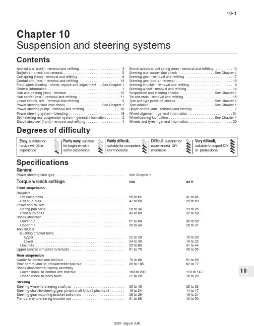
10Chapter 10Suspension and steering systemsGeneralPower steering fluid type . . . . . . . . . . . . . . . . . . . . . . . . . . . . . . . . . . . .See Chapter 1Torque wrench settingsNmlbf ftFront suspension BalljointsRetaining bolts . . . . . . . . . . . . . . . . . . . . . . . . . . . . . . . . . . . . . . . . . .55 to 6241 to 45Ball stud nuts . . . . . . . . . . . . . . . . . . . . . . . . . . . . . . . . . . . . . . . . . . .47 to 6835 to 50Lower control armSpring pan bolts . . . . . . . . . . . . . . . . . . . . . . . . . . . . . . . . . . . . . . . . .26 to 34 19 to 25Pivot nuts/bolts . . . . . . . . . . . . . . . . . . . . . . . . . . . . . . . . . . . . . . . . . .43 to 6832 to 50Shock absorberLower nut . . . . . . . . . . . . . . . . . . . . . . . . . . . . . . . . . . . . . . . . . . . . . .61 to 6845 to 50Upper nut . . . . . . . . . . . . . . . . . . . . . . . . . . . . . . . . . . . . . . . . . . . . . .35 to 4326 to 31Anti-roll barBushing bracket boltsUpper . . . . . . . . . . . . . . . . . . . . . . . . . . . . . . . . . . . . . . . . . . . . . . .22 to 2816 to 20Lower . . . . . . . . . . . . . . . . . . . . . . . . . . . . . . . . . . . . . . . . . . . . . . .24 to 3018 to 22Link nuts . . . . . . . . . . . . . . . . . . . . . . . . . . . . . . . . . . . . . . . . . . . . . . .55 to 6041 to 44Upper control arm pivot nuts/bolts . . . . . . . . . . . . . . . . . . . . . . . . . . . .61 to 7545 to 55Rear suspensionCarrier-to-control arm bolt/nut . . . . . . . . . . . . . . . . . . . . . . . . . . . . . . . .70 to 8051 to 59Rear control arm-to-crossmember bolt/nut . . . . . . . . . . . . . . . . . . . . . .85 to 10562 to 77Shock absorber/coil spring assemblyLower shock-to-control arm bolt/nut . . . . . . . . . . . . . . . . . . . . . . . . .160 to 200118 to 147Upper shock-to-body bolts . . . . . . . . . . . . . . . . . . . . . . . . . . . . . . . .22 to 2816 to 20SteeringSteering wheel-to-steering shaft nut . . . . . . . . . . . . . . . . . . . . . . . . . . .35 to 4526 to 33Steering shaft-to-steering gear pinion shaft U-joint pinch bolt . . . . . . .19 to 2414 to 17Steering gear mounting bracket bolts/nuts . . . . . . . . . . . . . . . . . . . . . .26 to 2919 to 21Tie-rod end-to-steering knuckle nut . . . . . . . . . . . . . . . . . . . . . . . . . . . .61 to 6845 to 50Anti-roll bar (front) - removal and refitting . . . . . . . . . . . . . . . . . . . . .3Balljoints - check and renewal . . . . . . . . . . . . . . . . . . . . . . . . . . . . . .5Coil spring (front) - removal and refitting . . . . . . . . . . . . . . . . . . . . . .8Control arm (rear) - removal and refitting . . . . . . . . . . . . . . . . . . . . .13Front wheel bearing - check, repack and adjustment . .See Chapter 1General information . . . . . . . . . . . . . . . . . . . . . . . . . . . . . . . . . . . . . .1Hub and bearing (rear) - renewal . . . . . . . . . . . . . . . . . . . . . . . . . . . .12Hub carrier (rear) - removal and refitting . . . . . . . . . . . . . . . . . . . . . .11Lower control arm - removal and refitting . . . . . . . . . . . . . . . . . . . . .9Power steering fluid level check . . . . . . . . . . . . . . . . . . .See Chapter 1Power steering pump - removal and refitting . . . . . . . . . . . . . . . . . .18Power steering system - bleeding . . . . . . . . . . . . . . . . . . . . . . . . . . .19Self-levelling rear suspension system - general information . . . . . . .2Shock absorber (front) - removal and refitting . . . . . . . . . . . . . . . . . .4Shock absorber/coil spring (rear) - removal and refitting . . . . . . . . .10Steering and suspension check . . . . . . . . . . . . . . . . . . .See Chapter 1Steering gear - removal and refitting . . . . . . . . . . . . . . . . . . . . . . . . .17Steering gear boots - renewal . . . . . . . . . . . . . . . . . . . . . . . . . . . . . .16Steering knuckle - removal and refitting . . . . . . . . . . . . . . . . . . . . . .6Steering wheel - removal and refitting . . . . . . . . . . . . . . . . . . . . . . . .14Suspension and steering checks . . . . . . . . . . . . . . . . . .See Chapter 1Tie-rod ends - removal and refitting . . . . . . . . . . . . . . . . . . . . . . . . .15Tyre and tyre pressure checks . . . . . . . . . . . . . . . . . . . .See Chapter 1Tyre rotation . . . . . . . . . . . . . . . . . . . . . . . . . . . . . . . . . .See Chapter 1Upper control arm - removal and refitting . . . . . . . . . . . . . . . . . . . . .7Wheel alignment - general information . . . . . . . . . . . . . . . . . . . . . . .21Wheel bearing lubrication . . . . . . . . . . . . . . . . . . . . . . . .See Chapter 1Wheels and tyres - general information . . . . . . . . . . . . . . . . . . . . . . .20SpecificationsContentsDegrees of difficulty1.2 Front suspension (left corner)1Anti-roll bar bushing bracket 2Anti-roll bar link 3Anti-roll bar 4Coil spring pan 5Lower control arm 6Coil spring7Upper control arm 8Lower balljoint 9Steering knuckle 10Tie-rod end 11Tie-rod12Steering gear boot10•2Suspension and steering systems1.1 Front suspension and steering systems1Anti-roll bar2Anti-roll bar bushing brackets 3Anti-roll bar links4Lower control arms 5Steering knuckles 6Tie-rod ends 7Tie-rods 8Steering gear boots 9Steering gear10Suspension crossmember11Lower control arm crossbrace1General informationWarning: Whenever any of thesuspension or steering fastenersare loosened or removed, theymust be inspected and if necessary, replaced with new ones of the same part number or of original equipment quality and design. Torque wrench settings must be followed for proper reassembly and component retention. Never attempt to heat, straighten or weld any suspension or steering component. Instead, renew any bent or damaged part.The front suspension (see illustrations) consists of unequal-length upper and lower control arms, shock absorbers and coil springs. The upper ends of the shocks are attached to the body; the lower ends are attached to the lower control arms. The upper ends of the coil springs are seated against the suspension crossmember; the lower ends are seated against removable plates which are bolted to the lower control arms. The steering knuckles are attached to balljoints in the upper and lower control arms. An anti-roll bar is attached to the suspension crossmember with a pair of bushing brackets and to the lower control arms via a connecting link at each end.The independent rear suspension (seeillustration)uses control arms and integralshock absorber/coil spring units. The upperends of the shocks are attached to the body;the lower ends are connected to the controlarms.The steering system consists of thesteering wheel, a steering column, a universaljoint on the lower end of the steering shaft, arack-and-pinion power steering gear, a powersteering pump and a pair of tie-rods whichconnects the steering gear to the steeringknuckles (see illustration).2Self-levelling rearsuspension system1988 to 1992 models were equipped with asystem that provided hydraulic power for therear suspension and for the power brakes. Asthe vehicle is loaded or unloaded, the rearsuspension is automatically adjusted tomaintain a constant ride height.The system was discontinued on 1993 andlater models, which are equipped withconventional shock absorber/coil spring units.A kit is available from your Jaguar dealershould you decide to retrofit the later,conventional shocks to a pre-1993 vehicle.Complete instructions for refitting the kit areincluded in Section 10.3Anti-roll bar (front)-removal and refitting21Raise the front of the vehicle and support itsecurely on axle stands.2Remove the bolts from the anti-roll barbrackets that attach the anti-roll bar to thesuspension crossmember (see illustration).3Remove the nuts that attach the anti-rollbar to the links (see illustration). If you’rereplacing the links themselves, or removingthe control arm, remove the nuts attaching thelinks to the lower control arms.Suspension and steering systems 10•3101.3 Rear suspension1 Hub carrier2 Control arms3 Crossmember mounting brackets4 Crossmember3.2 To detach the anti-roll bar from thesuspension crossmember, remove thesetwo bolts (arrowed) from each bushingbracket4Remove the anti-roll bar from the vehicle.5Refitting is the reverse of the removal procedure. Be sure to tighten all fasteners to the torque listed in this Chapter’s Specifications.4Shock absorber (front)-removal and refitting2Note: Always renew both left and right shocks at the same time to prevent handling peculiarities and abnormal ride quality.1Loosen but do not remove the front wheel nuts. Raise the front of the vehicle and support it on axle stands. Remove the wheels. 2Support the lower control arm with a trolley jack (see illustration). Place a block of wood between the jack head and the control arm to protect the arm and spring plate.3Remove the nut and bolt that attach the lower end of the shock absorber to the lower control arm (see illustration).4Remove the nut that attaches the upper end of the shock to the body (see illustration).5Remove the shock absorber.6Refitting is the reverse of removal. Tighten the fasteners to the torque listed in this Chapter’s Specifications.5Balljoints- check and renewal3Check1Raise the vehicle and support it securely onaxle stands.2Visually inspect the rubber boot betweenthe balljoints and the steering knuckle forcuts, tears or leaking grease. If you note anyof these conditions, renew the balljoint.3Place a large crowbar between eachcontrol arm and the steering knuckle. If youcan see or feel any movement during eithercheck, a worn-out balljoint is indicated.4Have an assistant grasp the tyre at the topand bottom and shake the top of the tyre withan in-and-out motion. Touch the balljoint studnut. If any looseness is felt, suspect a worn-out balljoint stud or a widened hole in thesteering knuckle. If the latter problem exists,the steering knuckle should be replaced aswell as the balljoint.Renewal5Loosen the wheel nuts, raise the vehicleand support it securely on axle stands.Remove the wheel.6Support the lower control arm with a trolleyjack (see illustration 4.2). Place a block ofwood between the jack head and the controlarm as shown to protect the arm and springplate.Upper balljoint7Loosen - but don’t remove - the ball studnut, fit a small puller (see illustration)andpop the ball stud loose from the steeringknuckle.8Remove the two bolts that attach theballjoint to the upper arm (see illustration).Count the number of shims installed and setthem aside.9Refitting is the reverse of removal. Don’tforget to refit the same number of shims.Tighten the bolts to the torque listed in thisChapter’s Specifications.10Remove the jack from under the controlarm, refit the front wheel, lower the vehicleand tighten the wheel nuts to the torque listedin the Chapter 1 Specifications. Drive thevehicle to an alignment workshop to have thewheel alignment checked, and if necessary,adjusted.Lower balljoint11Loosen - but don’t remove - the ball studnut, then give the steering knuckle a fewsharp raps with a hammer to pop the ball studloose (see illustration). Remove the ball studnut.10•4Suspension and steering systems3.3 To disconnect the anti-roll bar from the link, remove the upper nut (arrowed); to disconnect the link from the lower controlarm, remove the lower nut (arrowed)4.2 Support the lower control arm with a jack; put a block of wood between the jack head and the control arm to protect thearm and coil spring plate4.3 To disconnect the lower end of the shock absorber from the lower controlarm, remove this nut and bolt4.4 To disconnect the upper end of theshock absorber from the body, remove thisnut (arrowed)5.7 To detach the upper balljoint from thesteering knuckle, loosen the ballstud nut,fit a small puller and break the ballstudloose from the knuckle5.8 Remove the bolts and shims from theupper balljoint; be sure to put the shimsback when refitting the new balljoint12Remove the four balljoint retaining bolts (see illustration).13If the dust boot is damaged, pry it out (see illustration).14Remove the balljoint.15Refitting is the reverse of removal. Tighten the balljoint bolts and the ball stud nut to the torque listed in this Chapter’s Specifications. 16Remove the jack from under the control arm, refit the front wheel. Lower the vehicle and tighten the wheel nuts to the torque listed in the Chapter 1 Specifications.6Steering knuckle- removal and refitting31Loosen the wheel nuts, raise the front of the vehicle and place it securely on axle stands. Remove the wheel.2Remove the front brake caliper and mounting bracket (see Chapter 9). Do not disconnect the brake hose. Hang the caliper out of the way with a piece of wire.3Remove the brake disc (see Chapter 9).4Remove the ABS sensor (see illustration). 5Remove the brake shield (see illustration). 6Disconnect the tie-rod end from the steering knuckle (see Section 15).7Disconnect the upper and lower balljoints from the steering knuckle (see Section 5).8Remove the steering knuckle.9Refitting is the reverse of removal. Tighten the balljoint nuts and the tie-rod end nuts to the specified torque. Tighten the brake fasteners to the torque values listed in the Chapter 9 Specifications.7Upper control arm- removal and refitting31Loosen the wheel nuts, raise the vehicle and support it securely on axle stands. Remove the wheel.2Support the lower control arm with a trolley jack (see illustration 4.2).3Disconnect the upper balljoint from the steering knuckle (see Section 5).4If you’re removing the right upper controlarm on a vehicle equipped with the powerhydraulic system, remove the three Torxscrews which attach the accumulator (seeillustration)and push the assembly aside justfar enough to clear the pivot bolt.5Remove the upper control arm pivot boltand nut (see illustration). When removing thenut, note the number of washers used and theorder in which they’re installed. Put theseparts in a plastic bag.6Remove the upper control arm. Inspect thebushings at either end of the arm and renewthem if they’re damaged or worn.7Refitting is the reverse of removal. Be sureto refit the washers in the same order in whichthey were removed. Raise the suspensionwith the trolley jack to simulate normal rideheight, then tighten the upper control armpivot bolt and nut to the torque listed in thisChapter’s Specifications.8Coil spring (front)-removal and refitting3Warning: The coil springs cannotbe removed without a specialspring compressor tool (Jaguartool JD115). Do not try to removea coil spring without this special tool. If youdo, you could be seriously injured.1Loosen the wheel nuts, raise the vehicleSuspension and steering systems 10•5105.11 Strike the steering knuckle in this area to pop the lower ball stud loose fromthe steering knuckle 5.12 To detach the lower balljoint from thelower control arm, remove these four bolts(arrowed)5.13 To detach the dust boot from thesteering knuckle, pry the lower lip of theboot out of its groove in the knuckle6.5 To detach the brake shield from thesteering knuckle, remove these threescrews (arrowed)6.4 To detach the ABS sensor from thesteering knuckle, remove this bolt7.4 Remove these three Torx screws(arrowed) and move the accumulatorassembly to the side a little to provideclearance for pulling out the pivot bolt7.5 To detach the upper control arm fromthe crossmember, remove the nut (at therear) and pull the bolt out from the front;note the fitted order of the spacer washersand support it securely on axle stands. Remove the wheel.2Refit the special spring compressor tool (JD115) as shown (see illustrations).3Tighten the tool until the spacer is tight against the spring pan, then remove the spring pan bolts (see illustration).4Slowly back off the wingnut on the special tool until all tension is relieved from the spring. Remove the tool, remove the pan, and remove the coil spring.5Refitting is the reverse of removal. Place the coil spring in position with the spring pan below it, refit the special tool and carefully tighten the wingnut until the spring is compressed enough to allow the pan to be positioned and bolted to the lower control arm. Be sure to tighten the pan bolts to the torque listed in this Chapter’s Specifications. 9Lower control arm-removal and refitting3Warning: The lower control armscannot be removed without aspecial spring compressor tool(Jaguar tool JD115). Do not try to remove a lower control arm without this tool, or you could be seriously injured.1Loosen the wheel nuts, raise the vehicleand support it securely on axle stands.Remove the wheel.2Remove the spring pan and the coil spring(see Section 8).3Detach the steering gear (see Section 17)and lower it far enough to provide clearancefor the lower control arm pivot bolt.4Remove the pivot bolt and nut (seeillustration). Note any washers behind the nutand store them in a plastic bag.5Remove the lower control arm.6Refitting is the reverse of removal. Be sureto refit any washers removed. Raise thesuspension with the trolley jack to simulatenormal ride height, then tighten the pivot boltand nut to the torque listed in this Chapter’sSpecifications. Refer to Section 8 for coilspring refitting.10Shock absorber/coil spring(rear)- removal and refitting3Note 1: Always renew both left and rightshocks at the same time to prevent handlingpeculiarities and abnormal ride quality.Note 2:If you’re replacing the shock absorberson an earlier vehicle with the self-levellingsystem, we strongly recommend (and so doesJaguar) that you renew the self-levelling unitswith conventional units (available at the dealeras a retrofit kit for older vehicles equipped withthe self-levelling system).1Loosen the rear wheel nuts. Raise the rearof the vehicle and support it securely on axlestands. Remove the rear wheels. Support thecontrol arm with a trolley jack. Place a block ofwood on the jack head to serve as a cushion.2If you are removing/replacing the shocks ona vehicle equipped with the self-levelling rearsuspension system, depressurise the systemby pumping the brake pedal until it feels hardto push (this dissipates the pressure inside theaccumulator), then locate the hydraulic linevalve block just in front of the upper end of theleft rear shock (see illustration). Attach aplastic hose to the bleeder screw (seeillustration), put the other end of the hose in acatch bottle, crack the bleeder and drain offas much fluid as possible. Disconnect thehydraulic line that connects the left shock tothe valve block. Now locate the other valveblock just in front of the right rear shock;disconnect the hydraulic line that connectsthe right shock to this valve block too.3Remove the lower shock absorber-to-control arm nut and bolt (see illustration).4Remove the upper mounting bolts (seeillustration)and remove the shockabsorber/coil spring assembly.10•6Suspension and steering systems9.4 To detach the lower control arm from the crossmember, remove this nut and bolt (arrowed) (unbolt and lower the steeringgear before you can pull out the pivot bolt)10.2a On a vehicle equipped with self-levelling rear suspension, the valve block(arrowed) for the left rear shock is locatedjust in front of the shock absorber10.2b After depressurising the system,attach a bleed hose to the bleed screw onthe left valve block, open the bleed anddrain any residual fluid into a catch bottle8.2a When refitting the spring compressor tool (JD115), insert the upper end of therod into the cross-shaped slot in the suspension crossmember, then rotate the rod 90°so this pin on the upper end of thetool locks into the crossmember8.2b This is how the spring compressortool (JD115) looks when it’s installed; notehow the offset collet is oriented so that it’sflush with the coil spring pan8.3 To detach the coil spring pan from thelower control arm, compress the springand remove these six bolts (arrowed)5The shock/coil spring assemblies must be dismantled, and the coil springs installed on the new shocks. Although the shock/coil spring assembly is similar in appearance to the a MacPherson strut/coil spring assembly, the spring on this unit is much stiffer. Therefore, DO NOT attempt to take apart this unit yourself with a strut spring compressor tool. Instead, take the unit to a Jaguar dealer service department or to a Jaguar specialist workshop and have the springs installed on the new shocks by professionals.6If you are retrofitting conventional shocks -rather than refitting the same or another pairof self-levelling shocks - unplug the electricalconnector at the ride height sensor, and fillthe connector with silicone (see illustration)to prevent it from shorting out and causingelectrical problems. Then disconnect andremove all hydraulic lines (see illustrations).7Refitting is the reverse of removal. Be sureto tighten all fasteners to the torque valueslisted in this Chapter’s Specifications.8Remove the jack supporting the controlarm, refit the rear wheels and lower thevehicle.9Tighten the rear wheel nuts to the torquelisted in the Chapter 1 Specifications.10If you retrofitted conventional shocks to avehicle formerly equipped with the self-levelling rear suspension system, disconnectthe forward end of the hydraulic line from thevalve block and refit the plug included in thekit (see illustrations). Then finish removingthe forward section of hydraulic line and thebrackets for the line (see illustration).Suspension and steering systems 10•71010.6a Where applicable, unplug the connector to the ride height sensor and fillthe connector with silicone . . .10.6b . . . then disconnect and removeboth valve blocks . . .10.6c . . . and remove all associatedplumbing, including the metal line (arrow) tothe valve block in the engine compartment10.3 To detach the bottom of the shock absorber/coil spring fromthe control arm, remove this nut and bolt, then pull out the bolt 10.4 To detach the top of the shock absorber/coil spring from thebody, remove these bolts (arrowed) - not all bolts are visible here10.10a After the vehicle has been lowered,disconnect the forward end of thehydraulic line from the valve block . . .10.10b . . . refit the plug included in theretrofit kit . . .10.10c . . . then remove these bracketscrews (arrowed), the brackets and theforward section of hydraulic line11If you installed another pair of self-levelling shocks, or removed and installed the same pair of self-levelling shocks, be sure to top up the power hydraulic system reservoir (see Chapter 1).11Hub carrier (rear)- removal and refitting41Loosen the wheel nuts, raise the rear of the vehicle and support it securely on axle stands. Remove the wheel.2Remove the rear caliper and brake pads, the caliper bracket, the brake disc, the handbrake cable and the handbrake shoe assembly (see Chapter 9).3Disconnect the outer end of the propshaft from the hub carrier (see Chapter 8).4Remove the ABS sensor, the ABS harness clip and cut off the cable tie which secures the ABS harness to the carrier (see illustration). 5Remove the nut and bolt which attach the carrier to the control arm (see illustration).6Remove the hub carrier assembly.7Refitting is the reverse of removal. Be sure to tighten all fasteners to the torque values listed in this Chapter’s Specifications.12Hub and bearing (rear)-renewal4If you want to renew the rear hub and bearing assembly (or the ABS trigger wheel), remove the hub carrier (see Section 11), then take the carrier to a Jaguar dealer service department or to an automotive machine workshop. These parts require a hydraulic press and special fixtures to dismantle and reassemble.13Control arm (rear)-removal and refitting41Loosen the wheel nuts, raise the rear of thevehicle and support it securely on axle stands.Remove the wheel.2Remove the rear caliper and brake pads,the caliper bracket, the brake disc, thehandbrake cable and the handbrake shoeassembly (see Chapter 9).3Disconnect the outer end of the propshaftfrom the hub carrier (see Chapter 8).4Disconnect the lower end of the shockabsorber/coil spring assembly from thecontrol arm (see Section 10).5Remove the hub carrier (see Section 11).6Remove the control arm pivot bolt nut (seeillustration).7Support the differential/crossmemberassembly with a trolley jack. Place a block ofwood between the jack head and thedifferential to protect the differential.Disconnect the lower end of the differentialtie-bar (see illustration)and carefully lowerthe differential crossmember just enough toallow the control arm pivot bolt to be pulledout to the rear without hitting the boot well.8Remove the control arm.9Inspect the control arm pivot bolt bushings.If they’re cracked, dried out or torn, take thearm to an automotive machine workshop andhave them replaced.10Refitting is the reverse of removal. Tightenall suspension fasteners to the torque listed inthis Chapter’s Specifications. Tighten allbrake fasteners to the torque listed in theChapter 9 Specifications.14Steering wheel-removal and refitting1Warning: If your car is equippedwith an airbag, do not attemptthis procedure. Have it done by adealer service department orother qualified repair workshop.1Disconnect the negative battery cable.Caution: If the radio in your vehicle isequipped with an anti-theft system, make10•8Suspension and steering systems13.6 Hold the pivot bolt and unscrewthe nut 13.7 Remove this nut (arrowed) and bolt from the lower end of each tie-bar (rightabove the control arm pivot)11.4 Before detaching the hub carrier from the rear control arm, remove the ABS sensor (left arrow), detach the ABS harness clip(right arrow) and cut the cable tie securing the harness 11.5 To detach the hub carrier from the rear control arm, removethe carrier-to-control arm nut and boltsure you have the correct activation code before disconnecting the battery.2Pry off the centre pad (see illustration).3Remove the steering wheel nut and mark the relationship of the steering wheel hub to the shaft (see illustration).4Slide the steering wheel off the steering shaft (see illustration).5Refitting is the reverse of removal. Make sure you align the match marks you made on the steering wheel and the shaft. Tighten the steering wheel nut to the torque listed in this Chapter’s Specifications.15Tie-rod ends- removal and refitting21Loosen the wheel nuts, raise the front of the vehicle and support it securely on axle stands. Remove the front wheel.2Back off the locknut that locks the tie-rod end to the tie-rod, then paint an alignment mark on the threads to ensure the new tie-rod end is installed in the same position (see illustration).3Loosen the nut on the tie-rod ball stud, then fit a small puller and pop the ball stud loose (see illustration). Remove the nut and separate the ball stud from the steering knuckle. Unscrew the tie-rod end from the tie-rod.4Refitting is the reverse of removal. Make sure you thread the tie-rod end all the way up to the mark on the threads, but no further. Tighten the ball stud nut to the torque listed in this Chapter’s Specifications. Tighten the locknut securely.5Have the toe-in checked and, if necessary, adjusted at a dealer service department or alignment workshop.16Steering gear boots- renewal21Remove the tie-rod ends (see Section 15).2Cut the boot clamps at both ends of the oldboots (see illustration)and slide off theboots.3While the boots are removed, inspect theseals in the end of the steering gear. If they’releaking, have them replaced by a dealerservice department or other qualified repairworkshop, or replace the steering gear with anew or rebuilt unit (see Section 17).4Slide the new boots into place and refit newboot clamps.5Refit the tie-rod ends (see Section 15).Suspension and steering systems 10•91014.4 To remove the steering wheel,simply pull it straight off15.2 Back off this locknut and mark thethreads to ensure that the new tie-rod endis installed properly15.3 Loosen the ball stud nut, fit a smallpuller and pop the ball stud loose from thesteering knuckle14.2 To remove the centre pad from the steering wheel,simply pry it off14.3 After removing the steering wheel nut, make a pair of alignment marks on the steering wheel and steering shaft toensure proper reassembly16.2 Cut off the boot clamps (arrowed)and slide the boot off the steering gear。
2011款保时捷卡宴电器系统车间维修手册(下册)97 电缆 Cayenne 9PA电缆9700IN 测量闭路电流工具名称类型编号说明P 9718PIWIS 检测仪专用工具工具必须用 PIWIS 检测仪 P 9718模拟式电流表或带长集成时间的数字式万用表(用于滤除电压峰值)来测量闭路电流。
数字式万用表在车辆上进行的准备工作笔记在测量闭路电流之前,请先确定车辆设备(I-编号),并借助附表的帮助来确定预期的闭路电流。
闭路电流的测量只能在冷车(发动机&制动器)上进行。
1. 关闭车辆上的所有车门及盖。
测量闭路电流页 530打印在德国,11/0697 电缆 Cayenne 9PA2. 读取故障记忆,必要时删除所显示的故障。
3. 断开蓄电池。
连接测量设备1. 使用鳄鱼夹将测量设备连接至蓄电池接地设备及车身接地设备。
2. 拔掉车身的接地端,并与车身牢牢接触。
现在,车辆的所有电流都会流过电流表。
测量请选择一个测量范围,确保仪表指针在刻度较大值一端的三分之一处(越大越好)。
在不中断的情况下切换测量范围。
在表中指定的等待时间段后,读取测量值。
1. 打开点火开关 10 秒钟。
2. 关闭点火开关。
3. 打开驾驶员侧车门并在车门开启时用螺丝刀封闭旋转锁销。
4. 用中控锁遥控器锁住车辆,关闭乘客席监控(在 1 秒内按遥控器按钮两次)。
5. 读取闭路电流。
笔记如果闭路电流值高于表中规定的值,则要系统地分析其原因。
推荐的故障诊断程序: 采用所连接的测量装置,先后拆下端子30的保险丝以及继电器。
注意拆卸保险丝和继电器时测量装置上显示的值,以检测电流的减小。
可能的测量值变化范围大约是 20%。
表中列出的值取决于蓄电池状况、室温和发动机温度。
读取测量范围:车辆锁定至少 20 分钟后,才读取测量范围。
mA从到20 分钟。
直到蓄电池没电最多 35测量闭路电流页 531打印在德国,11/0697 电缆 Cayenne 9PA控制单元设备闭合电路电流 mA0.3DME(电机)标准0.424分动箱(纵向锁)标准0.424横向锁0.5自动变速器标准ESP 0.5标准0.425空气悬架0.5驾驶员座椅(带记忆)0.5乘客座椅(带记忆)0.2空调标准0.5辅助加热器0.5倒车辅助1.9Kessy控制单元(带无线电遥控, 无防盗系统/遥控模块)2.8Kessy控制单元(带无线电遥控, 无防盗系统/“Keyless Go”(无钥匙启动))0.3安全气囊标准1车辆电气系统标准0.1拖车 Westfalia0.5风挡刮水器标准0.5轮胎压力控制0.55电气可调节转向柱3组合仪表标准0.25驾驶员侧前门(无驾驶员侧 & 乘标准客侧车门 LED)0.25乘客侧前门标准0.25左后门标准0.25右后门标准1.4带(不带)蓄电池喇叭的后部控制单元0.5全景式天窗0.5收音机 CDR232.4PCM(CDR 23 的更高速档)0.11导航(PCM 的更高速档)测量闭路电流页 532打印在德国,11/0697 电缆 Cayenne 9PA 0.95CD 换碟机0.03天线放大器0.2电话/车载信息系统0.5后部娱乐设备0.3放大器3.6乘客席监控倾斜传感器0.05选档杆模块1.62蓄电池喇叭1拖车防盗控制6. 接上蓄电池并读出故障记忆。

2010 911中文维修手册一、概述2010年发布的911是保时捷汽车公司的一款具有里程碑意义的车型,它融合了现代科技和经典设计,成为了汽车界的一大亮点。
保时捷911车系因其卓越的性能和可靠的质量而备受全球车迷的喜爱,而911中文维修手册的问世更是极大方便了我国地区的车主和维修人员。
二、911中文维修手册的重要性1. 丰富的内容911中文维修手册详细介绍了此车型的结构、原理、维修方法和注意事项,对整车的每个部件、系统和功能都进行了清晰而全面的描述,使车主和专业维修人员能够深入了解和掌握其维修知识。
2. 提高维修效率有了911中文维修手册,维修人员可根据手册内容第一时间找到问题的所在,了解修理的难易程度和耗时程度,为维修过程提供了有力的帮助,提高了维修效率。
3. 确保维修质量手册中包含了品牌冠方认证的技术维修指南,依据最新的维修工艺和标准进行维修操作,能够准确诊断和解决车辆问题,保障维修质量。
三、911中文维修手册的特点1. 全面性911中文维修手册对车辆的机械结构、电气系统、车辆诊断、维修保养等方面进行了全面而深入的介绍,涵盖了车辆的各个系统和维修细节。
2. 高清晰度手册中的图片和图表经过细致处理和编辑,清晰度高,能够让读者一目了然地了解车辆的结构和维修细节,尤其对于维修人员来说,是一份宝贵的参考资料。
3. 实用性911中文维修手册由专业技术团队编写审核,内容准确可靠,操作性强,具有实用性和可操作性。
四、911中文维修手册的更新和持续优化1. 更新频率保时捷公司会根据车型的升级和变化情况,时刻关注车主和维修人员的反馈和需求,不断对维修手册进行更新和完善,确保手册始终与车型保持同步。
2. 客户需求保时捷公司注重客户需求,积极倾听车主和维修人员的建议和意见,不断对维修手册进行持续优化,以满足用户的多样化需求。
五、结语911中文维修手册的推出对于我国地区的车主和维修人员而言无疑是一大利好消息,它不仅方便了车主的日常保养和维修,也提升了维修人员的专业水平。
技术信息911(996)小组3动力传输©Dr.Ing.h.c.F.Porsche AG使用保时捷车辆车间文件的前提条件这些数据包括:保时捷车辆的技术信息和修理说明,以及培训文件。
这些说明信息仅供车间和车间工作人员使用。
笔记•Dr.Ing.h.c.F.Porsche AG保留对版权的独家所有权。
•不得转交给第三方。
•若无Dr.Ing.h.c.F.Porsche AG的明确同意,不得复制图片和文字或将它们用于其他电子或印刷出版物。
修理保时捷车辆的一般前提条件这些说明是正确地进行专业化保养与修理的基础。
所介绍的这些工作过程的内容要求装配工人对产品有全面的了解并接受过一定程度的培训。
装配工人在进行任何工作之前,必须已经通过Dr.Ing.h.c.F.Porsche AG 专门为熟悉产品和装配而设立的培训计划和课程获得有关产品的知识。
掌握这种知识水平是执行所述工作的前提。
如果在未掌握这些知识的情况下进行所述的修理工作,Dr.Ing.h.c.F.Porsche AG概不负责。
保时捷车辆车身作业的前提条件所介绍的修理工作仅适用于标准情况。
只限专门从事车身修理的熟练人员进行此类工作。
车间应根据损坏的总体情况,自行判断是否可将车辆恢复成正常状况。
保时捷车辆的修理工作需要使用Dr.Ing.h.c. F.Porsche AG推荐和批准的工具和车间设备。
必须根据Dr.Ing.h.c.F.Porsche AG的钣金、喷漆和防蚀/防腐工作说明正确实施所有车身修理工作。
警告注释和安全指南警告注释和安全指南按警告符号旁边的相应提示文字(危险、警告、注意)分类。
危险如不遵守操作说明则必然导致死亡或重伤的警告。
警告如不遵守操作说明则可能会导致死亡或重伤的警告。
注意如不遵守操作说明则会导致轻伤或财产损失的警告。
为防止由于工作不当而导致伤害、损失车辆性能和交通安全性、或者损坏车辆,请仔细阅读这些警告注释和安全指南并严格遵守。
Dr.Ing.h.c.F.Porsche AG不可能为执行此项工作的人详细评估所有的危险状况。
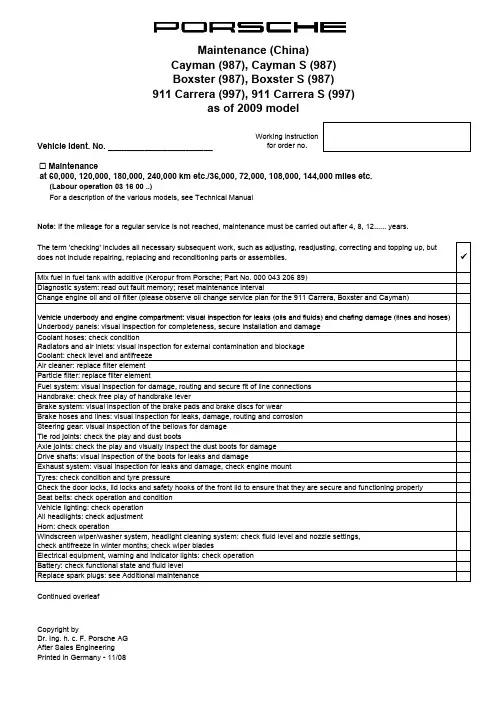
Vehicle Ident. No. _______________________Working instruction for order no.! Maintenanceat 60,000, 120,000, 180,000, 240,000 km etc./36,000, 72,000, 108,000, 144,000 miles etc.(Labour operation 03 16 00 ..)For a description of the various models, see Technical Manual Mix fuel in fuel tank with additive (Keropur from Porsche; Part No. 000 043 206 89)The term 'checking' includes all necessary subsequent work, such as adjusting, readjusting, correcting and topping up, but does not include repairing, replacing and reconditioning parts or assemblies.Change engine oil and oil filter (please observe oil change service plan for the 911 Carrera, Boxster and Cayman)"Note: If the mileage for a regular service is not reached, maintenance must be carried out after 4, 8, 12...... years.911 Carrera (997), 911 Carrera S (997)Boxster (987), Boxster S (987)as of 2009 modelDiagnostic system: read out fault memory; reset maintenance intervalVehicle underbody and engine compartment:visual inspection for leaks (oils and fluids)and chafing damage (lines and hoses)Continued overleaf Copyright byElectrical equipment, warning and indicator lights: check operationVehicle lighting: check operationAll headlights: check adjustmentHorn: check operationHandbrake: check free play of handbrake leverExhaust system: visual inspection for leaks and damage, check engine mountBrake hoses and lines: visual inspection for leaks, damage, routing and corrosionSteering gear: visual inspection of the bellows for damageTie rod joints: check the play and dust bootsSeat belts: check operation and conditionAir cleaner: replace filter elementFuel system: visual inspection for damage, routing and secure fit of line connectionsParticle filter: replace filter elementDrive shafts: visual inspection of the boots for leaks and damageBrake system: visual inspection of the brake pads and brake discs for wearTyres: check condition and tyre pressureCheck the door locks, lid locks and safety hooks of the front lid to ensure that they are secure and functioning properly Axle joints: check the play and visually inspect the dust boots for damageVehicle underbody and engine compartment: visual inspection for leaks (oils and fluids) and chafing damage (lines and hoses)Underbody panels: visual inspection for completeness, secure installation and damageCoolant hoses: check conditionRadiators and air inlets: visual inspection for external contamination and blockageCoolant: check level and antifreezeWindscreen wiper/washer system, headlight cleaning system: check fluid level and nozzle settings,check antifreeze in winter months; check wiper bladesReplace spark plugs: see Additional maintenanceBattery: check functional state and fluid levelpy g y Dr. Ing. h. c. F. Porsche AGAfter Sales EngineeringPrinted in Germany - 11/08Vehicle Ident. No. _______________________Working instruction for order no.! Additional maintenance for spark plugs(Labour operation 03 81 00 ..)"! Additional maintenance for drive belt (Labour operation 03 60 00 ..)! Additional maintenance for convertible top(Labour operation 03 70 00 ..)! Additional maintenance every 90,000 km/54,000 miles or every 6 years (Labour operation 03 83 00 ..)as of 2009 modelService and maintain convertible top (911 Carrera only)every 30,000 km/18,000 miles or every 2 years Replace spark plugs every 30,000 km/18,000 miles or every 4 years Check drive belt every 60,000 km/36,000 miles or every 4 years every 150,000 km/90,000 miles or every 10 years Check drive beltCheck drive belt every 240,000 km/144,000 miles or every 16 years Boxster (987), Boxster S (987)R l d i b lt911 Carrera (997), 911 Carrera S (997)Controlled all-wheel (only Carrera 4) : change oil! Additional maintenance every 180,000 km/108,000 miles or every 12 years(Labour operation 03 88 00 ..)! Every 2 yearsFile condition report for long-life guarantee! Every 4 years! After 4 years, then every 2 years! After 4, 8, 10 years, then every 2 yearsSignature (mechanic): _______________________________Test drive:Oils, fluids: visual inspection for leaksSignature (final check): _________________________Remote control, front seats, footbrake and handbrake (also actuation travel), engine, clutch, steering, transmission, ParkAssist, cruise control, PSM switch, PASM switch, Sport switch, heating, air conditioning and instruments: check operation Manual transmission: change oilAncillary unit mounts and suspension: visual inspection of all rubber mountings and boots for damageChange brake fluidReplace tyre sealantCheck tyre pressure monitoring system batteryPDK transmission: change clutch fluidReplace drive belt PDK transmission: change transmission oilAll-wheel final drive: change oil (911 Carrera only)Copyright byDr. Ing. h. c. F. Porsche AGAfter Sales EngineeringPrinted in Germany - 11/08Porsche Centre。

Cayenne、Cayenne S、Cayenne GTS、Cayenne S Transsyberia驾驶手册Porsche、保时捷盾徽、Cayenne、PCCB、PCM、PSM、Transsyberia、Tiptronic和精装配件均为Dr. Ing. h.c. F. Porsche AG 的注册商标。
中国印刷。
未经 Dr. Ing. h.c. F. Porsche AG 书面授权,不得再版、摘录或复印本手册。
© Dr. Ing. h.c. F. Porsche AGPorscheplatz 1D-70435 Stuttgart行车参考文件请将此文件随车携带,并在转售车辆时移交给新的车主。
建议如果您对您的车辆或本行车参考文件有任何疑问、建议或想法,请与我们联系:Dr. Ing. h.c. F. Porsche AGVertrieb Customer RelationsPorschestraße 15–1971634 Ludwigsburg 设备由于我们对车辆的创新与开发从未停止,因此您车辆的实际设备与规格可能与本驾驶手册中图示或描述的内容有所不同。
在我们出售的车辆中,某些设备可能属于选装件,或者根据法律要求或国家的不同而有所改变。
您的保时捷中心将乐于为您提供这些装备的加装服务。
如果您的保时捷安装了任何本手册中未描述的装备,为您服务的保时捷中心将乐于提供相关的正确操作及保养建议。
由于各个国家的法律要求不同,您车辆上的装备可能与本驾驶手册中的描述略有不同。
在中国市场仅供应 Cayenne 汽油版车型。
WKD 948 093 1002/09354目录概览图示 (4)驾驶员侧驾驶室 (5)方向盘和仪表组 (6)前部中控台 (7)开启和锁止 (8)概述 – 从车外开启和锁止 (9)从车外开启和锁止 (10)从车内开启和锁止 (18)开启和关闭发动机盖 (20)开启和关闭时的故障 (21)关于车匙和中控锁系统的注意事项 (23)座椅、后视镜和方向盘 (25)前排座椅 (26)带位置记忆功能的前排座椅 (27)便捷出入功能 (29)座椅头枕 (30)灭火器 (31)前排和后排座椅加热 (31)安全带 (33)安全气囊系统 (36)儿童约束系统 (38)车门镜 (44)内后视镜 (46)自动防眩目内后视镜 (46)方向盘 (47)加热式方向盘 (47)方向盘调节 (48)多功能方向盘..............................................49遮阳板 (51)化妆镜 (51)后侧车窗遮阳卷帘 (51)空调、辅助加热器和后窗加热系统 (52)开启盖罩 (53)空调系统综述 (53)适用于每一款空调系统 (54)概述 – 手动控制空调系统 (55)手动控制空调系统 (56)概述 – 自动控制2 区域空调系统 (58)自动控制 2 区域空调系统 (59)概述 – 自动控制 4 区域空调系统,前控制面板 (62)概述 – 自动控制 4 区域空调系统,后控制面板 (63)自动控制 4 区域空调系统 (64)出风口 (68)加热式后窗 (69)辅助加热器/附加加热器 (70)车窗和滑动式天窗 (75)电动车窗 (76)概述 – 滑动/举升式天窗 (79)滑动/举升式天窗 (80)概述 – 全景式天窗系统 (84)全景式天窗系统 (85)全景式天窗系统的紧急操作 (89)车灯、转向指示灯和挡风玻璃雨刷器 (91)灯光开关 (92)仪表板照明 (93)手动大灯光束调节 (94)自动大灯光束调节 (94)转向指示灯/远光灯/大灯远近光操纵杆 (95)危险警示灯 (95)车内照明灯 (96)舒适照明 (97)回家照明功能(延迟关闭) (98)门控灯 (98)概述 – 挡风玻璃雨刷器 (99)挡风玻璃雨刷器/清洗器操纵杆 (100)目录1多功能显示器和仪表 (103)汽油发动机车型的仪表板 (104)柴油发动机车型的仪表板 (106)机油温度表 (108)转速表 (108)时钟 (108)燃油表 (108)车速表 (108)里程显示 (108)电位计 (109)冷却系统 (109)Cayenne(V6)和Cayenne Diesel的智能保养电脑 (110)排放控制 (111)柴油发动机故障 (111)操作仪表板上的多功能显示器 (112)打开主菜单 (113)操作示例:显示平均油耗 (113)显示/复位平均车速 (115)显示剩余燃油可达里程 (115)显示轮胎气压 (115)显示罗盘 (115)通过多功能显示器使用电话 (116)在多功能显示器上设置限速 (117)显示警告信息 (118)显示车身水平高度控制系统的状态 (119)显示锁止系统/越野档的状态 (119)显示平均油耗 (120)设置轮胎气压监控 (120)在多功能显示器上关闭车内监控和倾斜传感器 (129)车门镜同步调节 (129)改变车辆解锁和锁止设置 (130)开启/关闭日间行车灯..............................132设置照明延迟关闭. (133)设置时钟 (133)设置罗盘 (134)更改显示语言 (135)更改显示单位 (135)将显示复位到出厂设置 (135)警告信息综述 (136)驾驶和行驶安全 (144)开车之前 (145)磨合技巧 (145)回收利用 (145)技术改造 (146)尾管 (146)Porsche 陶瓷复合制动系统(PCCB) (146)点火锁/转向锁 (147)起动和关闭发动机 (149)手机和双向无线电通讯 (150)Porsche 通讯管理系统(PCM) (150)收音机 (150)iPod、USB 和 AUX 接口 (151)停车制动器 (152)脚制动器 (152)巡航定速控制 (154)手动变速箱、离合器 (156)Tiptronic S (157)选档杆位置 (158)用于公路和越野驾驶的驾驶程序 (165)变速箱和底盘控制系统 (169)带有车身水平高度控制和高度调节功能的气动悬挂系统 (179)Porsche 主动悬挂管理系统(PASM) (182)Porsche 动态底盘控制(PDCC) (183)越野驾驶 (184)用于越野驾驶的行驶系统 (185)上坡道驾驶 (186)下坡道驾驶 (187)涉水驾驶 (188)跨越障碍物 (189)行李厢、装载区和储物空间 (191)向前折叠后排座椅及恢复到竖直位置 (192)装载区 (195)装载区管理系统 (196)装载 (199)行李厢盖 (200)行李安全网兜 (201)滑雪包 (203)车顶运输系统 (205)Cayenne S Transsyberia的车顶越野大灯 (206)储物空间 (207)杯座 (210)烟灰缸,前排 (212)烟灰缸,后排 (212)点烟器 (213)拖车钩 (214)拖车钩 (215)带有可拆卸式球形接头的拖车钩 (217)电动可伸出拖车钩 (222)驻车 (224)停车辅助系统 (225)作为停车辅助功能向下转动后视镜玻璃 (229)车库开门装置 (229)2目录防盗警报系统和防盗保护 (232)防盗警报系统 (233)防盗装置 (235)转向柱锁 (235)防盗保护 (235)保养和车辆养护 (236)保养注意事项 (237)检查机油油位 (238)添加机油 (239)检查冷却液液位并添加冷却液 (241)检查制动液液位并更换制动液 (243)洗涤液的添加 (244)更换空气滤清器 (245)更换微粒滤清器 (245)动力转向 (245)雨刷器刮片 (247)排放控制系统,汽油发动机 (249)燃油罐 (249)柴油微粒滤清器 (250)燃油和加油 (251)车辆养护说明 (253)小修 (261)小修注意事项 (262)轮胎和车轮 (263)千斤顶 (269)工具包 (269)充气泵 (270)厚垫片 (270)车轮螺栓 (271)维修漏气轮胎 (272)轮胎充气(不带车身水平高度控制系统的车辆)........282轮胎充气(带车身水平高度控制系统的车辆) (283)备用轮胎 (285)电气系统 (288)蓄电池 (297)更换遥控器电池 (300)外部电源,跨接起动 (301)更换灯泡 (303)大灯 (304)尾灯 (313)牌照灯 (315)大灯调整 (316)将左侧通行改为右侧通行时的大灯 (316)灯泡规格表 (317)牵引和牵引起动 (318)轮胎气压和技术数据 (322)车辆识别数据 (323)发动机技术数据 (324)耗油量和排放 (325)轮胎、车轮、轮距 (326)冷态(20°C)下的轮胎气压 (330)重量 (332)离地间隙 (333)容量 (335)尺寸 (336)行驶性能 (337)索引 (338)目录3概览图示驾驶员侧驾驶室 (5)方向盘和仪表组 (6)前部中控台 (7)4概览图示概览图示5驾驶员侧驾驶室1.电动车窗请参见第76页。
保时捷售后服务方案模板保时捷售后服务方案模板一、总览保时捷一直以来致力于为客户提供优质的售后服务。
我们深知客户的需求和期望,不仅提供高性能、高品质的汽车,更致力于为客户提供售后服务方案,以确保客户对汽车的满意度和持续支持。
二、售后服务目标我们的售后服务目标是满足客户的需求,确保客户对保时捷汽车的满意度,同时提供持续的支持和关怀。
我们的目标是在保时捷买车的全过程中,为客户提供最优质的售后服务。
三、服务内容1.定期保养:为客户提供定期保养服务,包括更换机油、更换滤清器、检查和调整发动机性能、检查和调整刹车系统、检查和调整悬挂系统等。
2.维修和维护:为客户提供维修和维护服务,包括故障排除、车身维修、电气系统维修、零部件更换等。
3.售后支持:为客户提供售后支持,包括电话咨询、在线咨询、现场支持等,以满足客户在使用过程中遇到的问题和需求。
4.配件供应:为客户提供原厂配件供应,以确保维修和更换零部件的质量和性能。
5.技术培训:为客户提供专业的技术培训,以提高客户对汽车维修和保养的技术能力。
6.车辆检测:为客户提供车辆检测服务,以确保汽车的性能和安全。
7.升级和改装:为客户提供升级和改装服务,包括改装发动机性能、改装悬挂系统、升级电子设备等。
四、服务流程1.售前咨询:客户在购车前可以通过电话、在线咨询等方式了解保时捷汽车的详情和相关服务。
2.购车手续:客户购车后,我们将为客户提供购车手续办理的便利和支持。
3.定期保养:根据车辆使用情况和保养周期,客户可以在指定的服务中心进行定期保养。
4.故障排除和维修:客户在使用过程中出现故障或需要维修时,可以与我们的服务中心联系,我们将为客户提供及时的故障排除和维修服务。
5.售后支持:客户在使用过程中遇到问题或需要帮助时,可以通过电话、在线咨询等方式与我们的客服中心联系,我们将及时提供支持和解决方案。
6.配件供应:客户在需要更换零部件时,可以与我们的服务中心联系,我们将为客户提供原厂配件,确保质量和性能。
最新全套保时捷维修资料------宝驰名车中心语言language:中文Chinese Italiano English Fran?ais Deutsch Espa?ol Japan日本2014-2015保时捷Macan 95B维修手册2014-2015保时捷918 Spyder 维修手册2013-2015保时捷帕拉梅拉Panamera 970维修手册2010-2012保时捷帕拉梅拉Panamera 970维修手册2012-2015保时捷卡雷拉Carrera911 991维修手册2006-2010保时捷卡雷拉Carrera911 996 997维修手册2012-2015保时捷Boxster, Cayman 981维修手册2009-2012保时捷卡曼Cayman 987维修手册2009-2012保时捷博克斯特Boxster 987维修手册2011-2012年保时捷卡宴Cayenne 92A维修手册2013-2015年保时捷卡宴Cayenne 92A维修手册2008-2011保时捷卡宴Cayenne 9PA维修手册2004-2006保时捷卡宴Cayenne 9PA维修手册2011-2014保时捷全车型常用保养维修手册2010-2013保时捷全车型编码故障码数据流汇集2009-2014保时捷全车型故障代码查询诊断帮助老款保时捷Porsche911维修手册老款保时捷Porsche968维修手册保时捷Macan 95B电路图保时捷918 Spyder电路图保时捷帕拉梅拉Panamera 970电路图保时捷帕拉梅拉Panamera 970电路图保时捷卡雷拉Carrera911 991电路图保时捷卡雷拉Carrera911 996 997电路图保时捷Boxster, Cayman 981电路图保时捷卡曼Cayman 987电路图保时捷博克斯特Boxster 987电路图保时捷卡宴Cayenne 92A电路图保时捷卡宴Cayenne 9PA电路图2005-2012保时捷电路图系统WDS2005-2015保时捷电路图系统WDS技术培训:保时捷Macan多媒体课程保时捷Panamera 多媒体课程保时捷918 Spyder多媒体课程保时捷911 Carrera多媒体课程保时捷卡宴Cayenne多媒体课程保时捷Boxster多媒体课程保时捷Hybrid技术多媒体课程保时捷舒适性电气系统多媒体课程保时捷PIWIS II诊断编程操作多媒体保时捷动力传输系统多媒体课程保时捷发动机电气系统多媒体课程保时捷PDK双离合器变速箱多媒体课程2015保时捷MacanDiesel MacanS MacanTurbo 95B培训手册2015保时捷918Spyder技术培训手册2014保时捷培训中心技师培训课件2014保时捷帕拉梅拉Panamera970所有车型技术培训手册2014保时捷卡曼981 Cayman CaymanS技术培训手册2014保时捷卡雷拉Carrera911 991 GT3技术培训手册2014保时捷电器CAN波形高级培训资料2014保时捷Macan 95B技术培训手册2014保时捷918 Spyder技术培训手册2014保时捷911 GT3技术培训手册2014 年款保时捷981 Cayman Cayman CaymanS培训手册2013年保时捷卡雷拉911 991Carrera CarreraS技术培训手册2013保时捷全车型电器诊断技术高级培训资料2013保时捷培训中心技师培训课件2013保时捷帕拉梅拉970 Panamera技术培训手册2013保时捷卡宴92A Cayenne发动机电器系统技术培训2013保时捷卡宴92A CayenneS Diesel技术培训手册2013保时捷卡宴92A Cayenne CayenneS Diesel 培训手册2013保时捷卡宴92A Cayenne CayenneS CayenneTurbo技术培训手册2013保时捷卡曼981 Cayman CaymanS 技术培训手册2013保时捷卡雷拉911Carrera4 Carrera4S技术培训手册2013保时捷博克斯特981 Boxster BoxsterS技术培训手册2012保时捷中心在线车型技师高级培训课程2012保时捷培训中心卡宴92A Cayenne培训课件2012保时捷培训中心技师培训课件2012保时捷帕纳梅拉970 Panamera技术培训手册2012保时捷卡宴92A Cayenne S Hybrid混合动力技术培训手册2012保时捷卡宴92A Cayenne CayenneS CayenneTurbo培训手册2012保时捷卡雷拉Carrera Carrera S 991技术培训手册2012保时捷车型发动机技师培训课件2012保时捷911 Carrera CarreraS技术培训手册2011保时捷培训中心技师培训课件2011保时捷卡宴92A Cayenne技术培训手册2010保时捷帕纳梅拉970 Panamera技术培训手册2009保时捷卡宴9PA Cayenne 技术培训手册2009保时捷卡宴9PA Cayenne Diesel技术培训手册2009保时捷卡雷拉Carrera997技术培训手册2009保时捷卡雷拉Carrera911技术培训手册2009保时捷987 Boxster Cayman技术培训手册2008保时捷卡宴9PA Cayenne CayenneS培训手册2007保时捷卡宴9PA Cayenne培训手册2007保时捷911 Carrera CarreraS技术培训手册2006保时捷卡曼987 CaymanS技术培训手册2006保时捷卡雷拉911 Carrera4 Carrera4S培训手册2006保时捷987 CaymanS技术培训手册2005保时捷卡宴9PA Cayenne CayenneS CayenneTurbo技术培训手册2005保时捷987 Boxster技术培训手册2005保时捷911卡雷拉CarreraS技术培训手册2004保时捷卡宴Cayenne 技术培训手册保时捷传动系统技术培训--认证技师课程保时捷底盘技术培训--认证技师课程保时捷发动机技术培训--认证技师课程保时捷电子和电气技术培训--认证技师课程保时捷发动机电器技术培训--认证技师课程保时捷诊断仪PIWIS_II技术培训课程保时捷金银铜级技师考试资料汇集保时捷技师基础培训资料技术会议与案例研讨:2005年保时捷技术会议与案例研讨2006年保时捷技术会议与案例研讨2007年保时捷技术会议与案例研讨2008年保时捷技术会议与案例研讨2009年保时捷技术会议与案例研讨2010年保时捷技术会议与案例研讨2011年保时捷技术会议与案例研讨2012年保时捷技术会议与案例研讨2013年保时捷技术会议与案例研讨保时捷PPN技术信息保时捷卡宴(92A)车主手册保时捷卡宴(9PA) 车主手册保时捷Macan车主手册保时捷918 Spyder车主手册保时捷帕拉梅拉Panamera 车主手册宝驰名车国际服务中心Bao Chi Super luxury car International Service Center。
车间指南911Carrera(997)小组0整车—概述使用保时捷车辆车间文件的前提条件这些数据包括:保时捷车辆的技术信息和修理说明,以及培训文件。
这些说明信息仅供车间和车间工作人员使用。
笔记♦Dr.Ing.h.c.F.Porsche AG保留对版权的独家所有权。
♦不得转交给第三方。
♦若无Dr.Ing.h.c.F.Porsche AG的明确同意,不得复制图片和文字或将它们用于其他电子或印刷出版物。
修理保时捷车辆的一般前提条件这些说明是正确地进行专业化保养与修理的基础。
所介绍的这些工作过程的内容要求装配工人对产品有全面的了解并接受过一定程度的培训。
装配工人在进行任何工作之前,必须已经通过Dr. Ing.h.c.F.Porsche AG专门为熟悉产品和装配而设立的培训计划和课程获得有关产品的知识。
掌握这种知识水平是执行所述工作的前提。
如果在未掌握这些知识的情况下进行所述的修理工作,Dr.Ing.h.c. F.Porsche AG概不负责。
保时捷车辆车身作业的前提条件所介绍的修理工作仅适用于标准情况。
只限专门从事车身修理的熟练人员进行此类工作。
车间应根据损坏的总体情况,自行判断是否可将车辆恢复成正常状况。
保时捷车辆的修理工作需要使用Dr. Ing.h.c.F.Porsche AG推荐和批准的工具和车间设备。
必须根据Dr.Ing.h.c.F.Porsche AG的钣金、喷漆和防蚀/防腐工作说明正确实施所有车身修理工作。
警告注释和安全指南警告注释和安全指南按警告符号旁边的相应提示文字(危险、警告、注意)分类。
危险如不遵守操作说明则必然导致死亡或重伤的警告。
警告如不遵守操作说明则可能会导致死亡或重伤的警告。
注意如不遵守操作说明则会导致轻伤或财产损失的警告。
为防止由于工作不当而导致伤害、损失车辆性能和交通安全性、或者损坏车辆,请仔细阅读这些警告注释和安全指南并严格遵守。
Dr.Ing.h.c.F.Porsche AG不可能为执行此项工作的人详细评估所有的危险状况。
最新全套保时捷维修资料------寶馳名車中心语言language:中文Chinese Italiano English Français Deutsch Español Japan日本2014-2015保时捷Macan 95B维修手册2014-2015保时捷918 Spyder 维修手册2013-2015保时捷帕拉梅拉Panamera 970维修手册2010-2012保时捷帕拉梅拉Panamera 970维修手册2012-2015保时捷卡雷拉Carrera911 991维修手册2006-2010保时捷卡雷拉Carrera911 996 997维修手册2012-2015保时捷Boxster, Cayman 981维修手册2009-2012保时捷卡曼Cayman 987维修手册2009-2012保时捷博克斯特Boxster 987维修手册2011-2012年保时捷卡宴Cayenne 92A维修手册2013-2015年保时捷卡宴Cayenne 92A维修手册2008-2011保时捷卡宴Cayenne 9PA维修手册2004-2006保时捷卡宴Cayenne 9PA维修手册2011-2014保时捷全车型常用保养维修手册2010-2013保时捷全车型编码故障码数据流汇集2009-2014保时捷全车型故障代码查询诊断帮助老款保时捷Porsche911维修手册老款保时捷Porsche968维修手册保时捷Macan 95B电路图保时捷918 Spyder电路图保时捷帕拉梅拉Panamera 970电路图保时捷帕拉梅拉Panamera 970电路图保时捷卡雷拉Carrera911 991电路图保时捷卡雷拉Carrera911 996 997电路图保时捷Boxster, Cayman 981电路图保时捷卡曼Cayman 987电路图保时捷博克斯特Boxster 987电路图保时捷卡宴Cayenne 92A电路图保时捷卡宴Cayenne 9PA电路图2005-2012保时捷电路图系统WDS2005-2015保时捷电路图系统WDS技术培训:保时捷Macan多媒体课程保时捷Panamera 多媒体课程保时捷918 Spyder多媒体课程保时捷911 Carrera多媒体课程保时捷卡宴Cayenne多媒体课程保时捷Boxster多媒体课程保时捷Hybrid技术多媒体课程保时捷舒适性电气系统多媒体课程保时捷PIWIS II诊断编程操作多媒体保时捷动力传输系统多媒体课程保时捷发动机电气系统多媒体课程保时捷PDK双离合器变速箱多媒体课程2015保时捷MacanDiesel MacanS MacanTurbo 95B培训手册2015保时捷918Spyder技术培训手册2014保时捷培训中心技师培训课件2014保时捷帕拉梅拉Panamera970所有车型技术培训手册2014保时捷卡曼981 Cayman CaymanS技术培训手册2014保时捷卡雷拉Carrera911 991 GT3技术培训手册2014保时捷电器CAN波形高级培训资料2014保时捷Macan 95B技术培训手册2014保时捷918 Spyder技术培训手册2014保时捷911 GT3技术培训手册2014 年款保时捷981 Cayman Cayman CaymanS培训手册2013年保时捷卡雷拉911 991Carrera CarreraS技术培训手册2013保时捷全车型电器诊断技术高级培训资料2013保时捷培训中心技师培训课件2013保时捷帕拉梅拉970 Panamera技术培训手册2013保时捷卡宴92A Cayenne发动机电器系统技术培训2013保时捷卡宴92A CayenneS Diesel技术培训手册2013保时捷卡宴92A Cayenne CayenneS Diesel 培训手册2013保时捷卡宴92A Cayenne CayenneS CayenneTurbo技术培训手册2013保时捷卡曼981 Cayman CaymanS 技术培训手册2013保时捷卡雷拉911Carrera4 Carrera4S技术培训手册2013保时捷博克斯特981 Boxster BoxsterS技术培训手册2012保时捷中心在线车型技师高级培训课程2012保时捷培训中心卡宴92A Cayenne培训课件2012保时捷培训中心技师培训课件2012保时捷帕纳梅拉970 Panamera技术培训手册2012保时捷卡宴92A Cayenne S Hybrid混合动力技术培训手册2012保时捷卡宴92A Cayenne CayenneS CayenneTurbo培训手册2012保时捷卡雷拉Carrera Carrera S 991技术培训手册2012保时捷车型发动机技师培训课件2012保时捷911 Carrera CarreraS技术培训手册2011保时捷培训中心技师培训课件2011保时捷卡宴92A Cayenne技术培训手册2010保时捷帕纳梅拉970 Panamera技术培训手册2009保时捷卡宴9PA Cayenne 技术培训手册2009保时捷卡宴9PA Cayenne Diesel技术培训手册2009保时捷卡雷拉Carrera997技术培训手册2009保时捷卡雷拉Carrera911技术培训手册2009保时捷987 Boxster Cayman技术培训手册2008保时捷卡宴9PA Cayenne CayenneS培训手册2007保时捷卡宴9PA Cayenne培训手册2007保时捷911 Carrera CarreraS技术培训手册2006保时捷卡曼987 CaymanS技术培训手册2006保时捷卡雷拉911 Carrera4 Carrera4S培训手册2006保时捷987 CaymanS技术培训手册2005保时捷卡宴9PA Cayenne CayenneS CayenneTurbo技术培训手册2005保时捷987 Boxster技术培训手册2005保时捷911卡雷拉CarreraS技术培训手册2004保时捷卡宴Cayenne 技术培训手册保时捷传动系统技术培训--认证技师课程保时捷底盘技术培训--认证技师课程保时捷发动机技术培训--认证技师课程保时捷电子和电气技术培训--认证技师课程保时捷发动机电器技术培训--认证技师课程保时捷诊断仪PIWIS_II技术培训课程保时捷金银铜级技师考试资料汇集保时捷技师基础培训资料技术会议与案例研讨:2005年保时捷技术会议与案例研讨2006年保时捷技术会议与案例研讨2007年保时捷技术会议与案例研讨2008年保时捷技术会议与案例研讨2009年保时捷技术会议与案例研讨2010年保时捷技术会议与案例研讨2011年保时捷技术会议与案例研讨2012年保时捷技术会议与案例研讨2013年保时捷技术会议与案例研讨保时捷PPN技术信息寶馳名車國際服務中心Bao Chi Super luxury car International Service Center。
更换保时捷迈凯(Porsche Macan)的水箱散热器风扇可能涉及复杂的操作,建议您在进行任何维修之前仔细阅读车辆的维修手册,或者寻求专业的汽车维修技师的帮助。
以下是一般性的步骤概述,但具体车型和情况可能有所不同,务必谨慎操作。
注意:维修涉及到车辆的机械和电气部件,如果您不熟悉汽车维修,建议寻求专业技术人员的帮助,以确保安全和正确性。
以下是更换保时捷迈凯水箱散热器风扇的一般步骤:
断开电池:为了安全起见,先断开车辆的负极电池连接。
排放冷却液:打开冷却液排放螺栓,将冷却液排放至合适的容器中。
确保环保处理废弃冷却液。
拆卸前部部件:根据车型,可能需要拆卸前保险杠、进气道、引擎罩等部件,以便访问散热器区域。
拆卸风扇连接:找到散热器区域的风扇连接器,将其断开。
卸下散热器风扇:根据车型,可能需要拆卸风扇固定螺栓,然后小心地卸下风扇装置。
安装新风扇:将新的散热器风扇装置安装回位,确保所有连接和固定螺栓正确安装。
连接风扇电源:将风扇连接器插回其原始位置。
重新组装部件:按相反的顺序重新安装拆卸的前部部件,如前保险杠、进气道等。
填充冷却液:根据车辆的冷却系统容量和要求,填充适量的新冷却液。
连接电池:连接车辆的负极电池连接。
测试:启动车辆,观察新的水箱散热器风扇是否正常运转,同时监测车辆冷却系统的温度。
请注意,这只是一般的步骤概述,实际操作可能因车型、年份和细节而有所不同。
强烈建议您在进行任何车辆维修时,参考保时捷迈凯的官方维修手册,并且如果您没有足够的维修经验,请寻求专业技术人员的帮助。
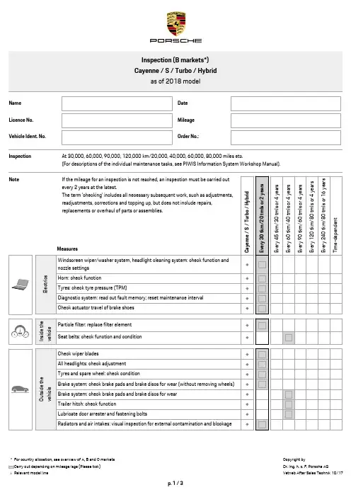
as of 2015modelVehicle Ident.No.Work instruction for order no.o Intermediate maintenance at 30000,90000,150000,210000km /18000,54000,90000,126000miles etc.(Labour operation:031400..)For descriptions of the individual maintenance tasks,see PIWIS Information System Workshop ManualNote:If the mileage for a regular service is not reached,intermediate maintenance must be carried out after 2,6,10...years.The term "checking"includes all necessary subsequent work,such as adjusting,readjusting,correcting and topping up,but does not include repairing,replacing and reconditioning parts or assemblies.üElectricsWindscreen wiper/washer system,headlight cleaning system:check function and nozzle settingsHorn:check functionTyres:check tyre pressure (TPM)Diagnostic system:read out fault memory and transfer gear wear integrator;reset maintenance interval Outside the vehicleCheck wiper bladesAll headlights:check adjustmentMix fuel in fuel tank with additive [Keropur from Porsche,Part No.00004320689(China only)]Under the vehicleDrain engine oilChange oil filterTyres and spare wheel:check conditionBrake lines:visual inspection for damage,routing and corrosionBrake hoses:visual inspection for damageBrake system:check brake pads and brake discs for wear (without removing wheels)Drive shafts:visual inspection of the boots for leaks and damageCardan shaft:visual inspection of the rubber bellows for damageRadiators and air intakes:visual inspection for external contamination and blockageEngine compartmentFill in engine oilCoolant:check level and antifreezeCheck drive belt (only if vehicle is used for off-road driving)Windscreen wiper/washer system:check fluid level;check window cleaner and antifreeze,depending on time of year,only use windscreen cleaners approved by PorschePDCC and power steering:check fluid levelThrottle housing:clean inside (China only)*For country allocation,see overview of A,B and C marketsas of 2015modelVehicle Ident.No.Work instructionfor order no.o Additional maintenance every 2years (Labour operation:035100..)Change brake fluid (use only original Porsche brake fluid)Clutch:change brake fluid;perform test and adaptation (Cayenne S E-Hybrid)Tyre sealing compound:check use-by date and replace if necessaryPrepare condition report for long-life guaranteeo Additional maintenance for spark plugs(Labour operation:038100..)Replace spark plugs every 20,000km/12,000miles or every 2yearso Additional maintenance every 120000km /72000mls or every 4years(Labour operation:038500..)Air cleaner:replace filter element (Cayenne V6/S/Turbo/S E-Hybrid)o Additional maintenance every 240000km /144000mls or every 16years(Labour operation:039500..)Rear final drive:change oilTiptronic transmission:change ATF and ATF filterTransfer gear:change oil (Cayenne Diesel,S E-Hybrid,V6)All-wheel final drive:change oilo Additional maintenance every 90000km /54000mls or every 6years(Labour operation:038300..)Replace PDCC reservoirAir cleaner:replace filter element (Cayenne Diesel/S Diesel)Turbo compressor:replace drive belt (Cayenne 3.0V6,S E-Hybrid)Signature (mechanic):Test drive:Oils,fluids:visual inspection for leaksRemote control,front seats,electric parking brake and footbrake,engine,transmission,steering,ParkAssist,cruise control,PSM switch,heating,sports exhaust system,air conditioning and instruments:check functionSignature (final check):Porsche Centre。
保时捷Cayenne维修保养项目分类保时捷 Cayenne日常用车常规注意事项磨合:1500km首次保养:7500-10000km长期停放应将电瓶线拔掉,轮胎高压停车保时捷 Cayenne定期维护保养项目列表7500公里维护保养发动机传动系、转向系1.润滑系、冷却系、燃油系检查渗漏 1.变速器是否渗漏2.更换机油、机滤 2.万向节护套3.检查防冻液防冻能力3.转向横拉杆护套4.多楔齿带、正时齿带 4.转向节护套5.怠速转速、目视检查排放 5.减震器、叉形壁、橡胶连接件制动系、车轮、车身空调系、电器1.检查制动液 1.检查空调系统渗漏2.制动衬片 2.检查电瓶3.轮胎气压、磨损状态 3.目视检查接线柱、线束包、橡胶管、真空管4.润滑发动机罩铰链、锁舌5.润滑车门铰链、及车门拉手6.天窗、后备箱15000公里保养项目1.检查排气系统2.进行自诊断3.转向横拉杆间隙4.车门锁、儿童安全锁、安全锁扭5.检查灯光、喇叭、雨刮及清洗系6.保养周期复位7.空滤检查、花粉滤清器检查 8.检查火花塞9.检查传动带及张紧器30000公里保养项目1.检查排气系统2.进行自诊断3.转向横拉杆间隙4.车门锁、儿童安全锁、安全锁扭5.检查灯光、喇叭、雨刮及清洗系6.保养周期复位7.空滤检查、花粉滤清器检查 8.检查火花塞9.检查传动带及张紧器60000公里保养项目1.更换自动变速箱油2.更换火花塞4.建议更换正时齿带及张紧器(6-9万) 3.更换制动液(24个月)5.检查三元催化器6.检查氧传感器工作状态7.更换空气滤清器清洗壳体保时捷 Cayenne 维护保养分类12个月维护保养 24个月维护保养36个月维护保养 14年维护保养120000公里更换正时齿带及多携带及张紧器15年更换安全气囊。
997 中文维修手册
《997中文维修手册》是一本详细介绍保时捷911(型号997)维修和保养的手册。
这本手册提供了全面的信息,旨在帮助车主和维修人员了解如何正确维护和修理911(997)车型。
手册的内容包括以下几个方面:
1. 车辆介绍:手册首先会对911(997)车型进行详细介绍,包括车辆的外观、内饰、动力系统、悬挂系统等方面的特点和技术参数。
这部分内容让读者对车辆有一个整体的了解。
2. 维修指南:手册提供了维修和保养的详细指南。
这包括了车辆的常见故障和维修方法,如发动机故障、电气系统故障、制动系统故障等。
手册会给出具体的排查和修复步骤,以及所需的工具和材料。
3. 保养计划:手册还包含了911(997)车型的保养计划。
这包括了定期更换机油、滤清器、火花塞等常规保养项目的时间和方法。
手册还会提供一些保养技巧和注意事项,以确保车辆保持良好的运行状态。
4. 零部件目录:手册提供了911(997)车型的零部件目录。
这包括了车辆的各个系统的零部件图和编号,以及它们的功能和安装位置。
这部分内容对于需要更换零部件或进行维修的人员非常有用。
5. 故障代码解读:手册还包含了911(997)车型的故障代码解读。
这些故障代码是由车辆的电脑系统自动检测并记录的,手册会解释每个故障代码的含义和可能的原因。
这对于快速定位和解决
故障非常有帮助。
总之,《997中文维修手册》是一本非常实用的手册,提供了丰富的信息和指导,帮助车主和维修人员正确维护和修理保时捷911(997)车型。
无论是初学者还是有经验的维修人员,都可以从中受益。