SVI-2中文操作手册
- 格式:pdf
- 大小:2.95 MB
- 文档页数:43

M aso n eilan*S V I*II A P 定位器作业指导书编制:周利鹏审核:王振辉储运公用成品油班组SVI II AP定位器作业指导书1、工作原理SVI II AP是智能电气定位器,它从控制器接收4-20mA电气位置设定点信号并与阀门位反馈传感器比较位置设定点输入信号。
位置设定点和位置反馈之间的差异通过位置控制算法分析计算输出为I/P转换器设定伺服信号。
I/P的输出压力由驱动执行机构的气动气路放大器放大。
一旦设定点和阀门位反馈之间的误差在范围之内,对伺服信号不进行其它纠正,以保持阀位。
阀门定位器外观如图1-1所示。
1-1 SVI II AP2、电气模块接线端子板如图2-1所示。
2-1 接线端子图3、操作按钮本地按钮都位于铰链保护盖后面,显示窗口的正下方。
用一字螺丝刀将中间的螺丝拧开,将黑色盖子掀起,有三个银色按钮分别是‘*’(选择)、‘-’(向后)、‘+’(向前)如图(3-1)3-1 SVI II AP显示屏及操作按钮三个按钮执行以下功能:左按钮:标记为*,允许您选择或接受当前显示的值或参数选项。
中间按钮:标记为-,允许您通过菜单结构返回上一个菜单项目,或者减少数字显示屏上当前显示的值。
当用于减小显示值时,长按按钮就会使值以更快速度减小。
右键按钮:标记为+,允许您通过菜单结构进入下一个菜单项目,或者增加数字显示屏上当前显示的值。
当用于增加显示值时,长按按钮就会使值以更快速度增加。
4、NORMAL 运行模式和 MANUAL 模式菜单当离开NORMAL模式进入MANUAL模式时,阀门处于它离开NORMAL时所处的最后位置。
在MANUAL模式下,设备不会对4-20 mA的信号作出响应。
但是,SVI II AP设备仍然可以对HART命令作出响应,包括定位阀门的HART命令。
当你从NORMAL运行模式菜单切换到VIEW DATA或VIEW ERR菜单,阀门仍然处于NORMAL 模式,并且仍然对4-20mA信号作出响应。

锐捷S3550配置手册第一部分:交换机概述一:交换机的几种配置方法控制台远程登录通过一台连接在网络中的计算机,用Telnet命令登录网络设备进行配置。
其它配置方法除了控制台和远程登录之外,还有其它一些配置方法配置网络设备。
二:命令行(CLI)操作命令模式交换机和路由器的命令是按模式分组的,每种模式中定义了一组命令集,所以想要使用某命令模式的切换交换机和路由器的模式大体可分为四层:用户模式→特权模式→全局配置模式→其它配置CLI命令的编辑技巧CLI(命令行)有以下特点。
常见CLI错误提示% Ambiguous command: "show c"使用no 和default 选项很多命令都有no 选项和default 选项。
三:交换机的初始化配置交换机的初始化配置setup命令四:配置文件的保存、查看与备份查看配置文件模式:特权配置模式。
保存配置文件就是把running-config 保存为startup-config。
删除配置文件删除配置文件就是把NVRAM中的startup-config 删除。
通常我们把配置文件备份到TFTP服务器上,在需要时可以再从TFTP服务器上把配置文五:文件系统文件系统概述交换机和路由器用一个并行Flash作为辅助存储器存储文件,Flash是一个可读可写的存文件操作所有文件操作都是在特权模式下进行。
目录操作Flash中的文件可以使用树形的目录结构,文件可以存放在不同的子目录中,也可以在目六:系统文件的备份与升级搭建环境在备份和升级时需要搭建通信环境,让设备和计算机间可以传输文件。
有三个方案:用TFTP传输文件准备工作:用Xmodem传输文件准备工作:ROM监控模式进入ROM监控模式有两种方法:七:密码丢失的解决方法第二部分:交换机的基本配置一:配置主机名主机名用于标识交换机和路由器,通常它会作为提示符的一部分显示在命令提示符的前二:配置口令配置控制台口令控制台口令是通过控制台登录交换机或路由器时设置的口令。

生料—II微机系统操作规程一、总则1.1 本规程是为确保生料-II微机系统的正常操作、维护和管理,保证生产过程中数据的可靠性和完整性制定的管理规程。
1.2 所有使用生料-II微机系统的人员必须遵守本规程的规定。
1.3 用户使用生料-II微机系统的权限由系统管理员进行管理,具体使用权限根据用户职责和工作需要予以分配。
二、系统登录2.1 在登录生料-II微机系统前,用户应首先了解系统内数据的重要性,保持数据安全和保密。
2.2 用户使用正确的用户名和密码登录系统,系统将自动记录登录时间和用户名,用户应严格遵守有关信息安全的规定。
2.3 用户在登录后必须及时维护其口令的保密性,防止泄漏和被盗用,若口令遗失或被非法窃取,必须立即向系统管理员报告。
2.4 操作完毕后,用户应选择安全退出,以保证数据和系统的安全。
三、数据操作3.1 生料-II微机系统的数据应按照规定的数据结构和数据定义来使用,以保证数据的准确性。
3.2 在使用生料-II微机系统进行数据输入、修改和查询时,用户应按照规定的格式进行操作。
如有录入错误或其他异常情况应及时更正或报告系统管理员。
3.3 生料-II微机系统中的数据仅限本部门或工作岗位人员使用,任何情况下不得向外泄露或转移。
3.4 使用生料-II微机系统时应注意数据的备份和存储,确保数据的安全性和完整性。
四、系统运维4.1 系统管理员应定期维护和管理系统,保证系统的稳定运行。
4.2 系统管理员应定期对系统进行数据备份和存档,以保障数据的安全性和完整性,确保备份数据和原始数据的一致性。
4.3 系统管理员应对系统进行故障排查、处理,确保系统的稳定运行。
在操作过程中,管理员应保证系统的安全稳定,防止不必要的风险发生。
五、制度管理5.1 生料-II微机系统使用过程中出现的问题,应及时报告系统管理员,由管理员进行处理和解决。
5.2 对于严重违规者,系统管理员应立即采取相应的处理措施。
5.3 所有参与生料-II微机系统的用户必须严格遵守有关安全的规定,因操作失误造成的后果由责任人员承担。


原始说明ES-727在可能有爆炸性气体或易燃粉尘的区域中安装MASONEILAN SVI II ESD 的特殊说明目录介绍 (3)定义和缩写 (3)一般要求 (3)SVI-II ESD 的型号说明 (4)防火和防尘燃要求 (4)本安要求 (4)防火和本安标记说明 (5)8.本安安装注意事项 (8)9维修 (9)10历史记录 (11)附图图 1,*本安安装接线要求 (7)附表表 1:4-20mA 输入实体/NIFW 参数8表 2:4-20mA 输出实体/NIFW 参数9表 3:PV 1-5VDC 实体/NIFW 参数9表 4:SW 1 和 SW 2 实体/NIFW 参数9表 5:DI 实体/NIFW 参数9表 6:24 VDC 输入实体/NIFW 参数9介绍本手册涵盖在潜在爆炸性环境或易燃粉尘区域中操作 SVI II ESD 的安全安装、维修和操作要求。
遵守这些要求可确保 SVI II ESD 不会引起周围空气点燃。
与过程控制有关的危险不在本手册范围之内。
有关特定阀门的安装说明,请参阅安装套件随附的安装说明。
安装不会影响 SVI II ESD 在潜在危险环境中使用的适合性。
SVI II ESD 的制造厂商:Dresser LLC.12970 Normandy Blvd.Jacksonville FL 32221 –美国定义和缩写缩写全称解释SVI 智能阀门接口用于控制阀门的 Masoneilan 数字仪器ESD 紧急停机ASD 模拟安全需求4-20mA 为设备供电并启动安全功能DSD 离散安全需求24VDC 为设备供电并启动安全功能A/DSD 模拟/离散安全需求4-20mA 为设备供电,24VDC 启动安全功能一般要求!警告!不遵守本手册中列出的要求可能会导致生命和财产损失。
安装和维护只能由合格人员执行。
区域分类、防护类型、温度类别、气体组和进入防护必须符合标签所示数据。
接线和导线管必须符合管辖安装的所有当地和国家法规。
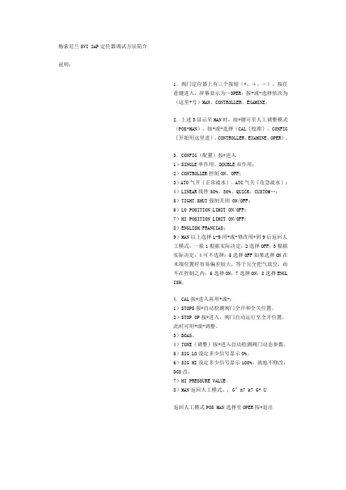
梅索尼兰SVI 2AP定位器调试方法简介说明:1.阀门定位器上有三个按钮(*、+、-),按任意键进入,屏幕显示为~OPER,按+或-选择依次为(这里+号)MAN、CONTROLLER、EXAMINE。
2.上述3显示至MAN时,按*键可至人工调整模式(POS-MAN),按+或-选择(CAL{校准}、CONFIG{开始用这里进}、CONTROLLER、EXAMINE、OPER)。
3.CONFIG(配置)按*进入1)SINGLE单作用、DOUBLE双作用;2)CONTROLLER控制ON、OFF;3)ATO气开{正常疏水}、ATC气关{危急疏水};4)LINEAR线性50%、30%、QUICK、CUSTOM…;5)TIGHT SHUT强制关闭 ON/OFF;6)LO POSITION LIMIT ON/OFF;7)HI POSITION LIMIT ON/OFF;8)ENGLISH/FRANCIAS;9)MAN以上选择1-9用+或-修改用*到9后返回人工模式。
一般1根据实际决定;2选择OFF;3根据实际决定;4可不选择;5选择OFF如果选择ON在末端位置时容易偏差较大,等于完全把气放空,而不在控制之内;6选择ON;7选择ON;8选择ENGLISH。
4. CAL按*进入再用+或-,1)STOPS按*自动检测阀门全开和全关位置。
2)STOP OP按*进入,阀门自动运行至全开位置,此时可用+或-调整。
3)BOAS。
4)TONE{调整}按*进入自动检测阀门动态参数。
5)SIG LO设定多少信号显示0%。
6)SIG HI设定多少信号显示100%。
就地不修改,DCS改。
7)HI PRESSURE VALUE。
8)MAN返回人工模式。
, G" n7 k7 G+ U返回人工模式POS MAN选择至OPER按*退出。
DE: Bedienungsanleitung - FR: Guide de l'utilisateur - ES: Guía del usuario - IT: Guida per l'uso - NL: Gebruiksaanwijzing - PT: Guia do usuário - SVID2USB2Video Capture Cable with Compositeand S-Video InputFCC Compliance StatementThis equipment has been tested and found to comply with the limits for a Class B digital device, pursuant to part 15 of the FCC Rules. These limits are designed to provide reasonable protection against harmful interference in a residential installation. This equipment generates, uses and can radiate radio frequency energy and, if not installed and used in accordance with the instructions, may cause harmful interference to radio communications. However, there is no guarantee that interference will not occur in a particular installation. If this equipment does cause harmful interference to radio or television reception, which can be determined by turning the equipment off and on, the user is encouraged to try to correct the interference by one or more of the following measures:Reorient or relocate the receiving antenna.Increase the separation between the equipment and receiver.Connect the equipment into an outlet on a circuit different from that to which the receiver is connected.Consult the dealer or an experienced radio/TV technician for help.Use of Trademarks, Registered Trademarks, and other Protected Names and SymbolsThis manual may make reference to trademarks, registered trademarks, and other protected names and/or symbols of third-party companies not related in any way to . Where they occur these references are for illustrative purposes only and do not represent an endorsement of a product or service by , or an endorsement of the product(s) to which this manual applies by the third-party company in question. Regardless of any direct acknowledgement elsewhere in the body of this document, hereby acknowledges that all trademarks, registered trademarks, service marks, and other protected names and/or symbols contained in this manual and related documents are the property of their respective holders.Table of ContentsIntroduction (1)Features (1)Before You Begin (1)System Requirements (1)Contents (1)Installation (2)Installing the drivers (2)Installing the GrabBee Mulitimedia Application (3)Hardware (4)GrabBee Multimedia Application operation (4)Specifications (7)Troubleshooting (8)Technical Support & Warranty Information (9)IntroductionThank you for purchasing a USB 2.0 Video Capture Card. The ideal solution for portable A/V applications, this product offers real-time MPEG 1, 2 and 4 recording, providing a perfect bridge between your computer and VCR, camcorder or any other S-Video source. Small enough to fit in the palm of your hand, SVID2USB2 integrates seamlessly with notebook and desktop computers.Features• Portable form factor for on-the-go applications• Offers USB 2.0 transfer rates (480Mbps) for high quality video capturing• Up to 30 fps motion capture capability at resolutions up to 720x480(NTSC) / 720x576(PAL)• SnapShot function allows you to capture still images• Brightness, contrast and sharpness controls offer an optimized viewing experience• Supports NTSC, PAL, and SECAM formatsBefore You BeginSystem Requirements• Pentium 4 based or equivalent PC, with an available USB 2.0 port• 128MB RAM• Windows 2000 SP3 or above, Windows XP SP1 or above• Sound cardContentsThis package should contain:• USB 2.0 Video capture cable• Installation and Driver CD• Instruction manualInstallation1. Prior to installing this device, please ensure that your computer has an available USB2.0 port,and that your operating system has been updated according to the most recent revisions (Windows XP SP1, Windows 2000 SP3 etc.). Also, please ensure that the USB2.0 host driver is updated according to the most modern version available.Please note: Before connecting SVID2USB2 to your computer, please ensure that the necessary drivers have been installed.Installing the drivers1. Please insert the Multimedia Installation Kit CD into your CD or DVD-ROM drive.2. Locate the folder entitled Driver, located in the GrabBee X + Deluxe folder on the DriverCD. Double-click on the Setup.exe file to launch the InstallShield Wizard. Once this window launches, please click on Next:3. The multimedia software will install automatically. Once complete, you will be notified thatSetup has finished installing USB Video/Audio Driver on your computer. Please click Finish:4. To complete the Setup Wizard installation process, please restart your computer. Once thecomputer has been rebooted, please insert the USB connector provided by SVID2USB2 into an available USB 2.0 slot on the computer. Windows will then automatically detect the connected device and conclude the necessary software installation.5. To verify that the installation was successful, locate and right-click on the My Computer icon(located on desktop or in Start menu), and select Manage. This will launch the Computer Management utility. Click on Device Manager, and click on the [+] symbol located next to Sound, video and game controllers, where you will now see two new additions - USB 2821 Device and USB EMP Audio Device:Please note: Although the multimedia application packaged with SVID2USB2 is designed specifically for use with this device, it is not required for use. For information about third party alternatives, please consult your local computer store or computer manufacturer for more information.Installing the GrabBee Multimedia Application1. Please insert the Multimedia Installation Kit CD into your CD or DVD-ROM drive.2. Locate the folder entitled AP Software, located in the GrabBee X + Deluxe folder on theDriver CD. Double-click on the Setup.exe file to launch the InstallShield Wizard. Once this window launches, please click on Next.3. The screen that follows will ask you to select the installation destination. Please enter anappropriate path (if it varies from the default), and click Next.4. When the Windows Media Format 9 Series Runtime Setup launches, please click Yes. Toadvance, please click Yes, when the License agreement is displayed. Once you are notified that installation has completed, please click OK.5. You will then be prompted to install Windows Media Tools. Please click Yes, and proceedthrough the installation steps, by clicking Next and Yes where applicable. To concludeinstallation, please click on Finish.6. Once the software has been installed, you may be prompted to reboot your computer.Please do so.SVID2USB2 HardwarePlease note: If you are using Windows 2000, please connect the audio from your external A/V device to the line-in port on your sound card.In order to launch the Multimedia application, you will first be required to connect the SVID2USB2 Video Capture Cable to your computer. Once the USB connection has been made, you will be able to configure the settings for the device, using the instructions below.GrabBee Multimedia Application OperationFollowing the installation of the GrabBee software, you will notice three new icons located on your desktop:USB connector Composite video input S-Video inputAudio L /R inputClick to launch the main programClick to view record files Click to view capturedstill image filesTo launch the main application, please click on the GrabBee icon. Once the application launches,you will see the following:OptionClick on Option on the control panel (illustrated above) to launch the following screen:Under the General tab, you will see the following:a) Hard disk space information b) Snapshot default storage path - The location to which captured images will be stored. c) Clip default storage path - The location to which captured video clips will be stored. d) Video Format - Allows you to choose the video input being usede) Set Recording Time - Allows you to set the recording lengthRight-click on the Video Window to launch the function menu, where you will be able to selectvideo resolution and screen size:Under the Encoder Property tab:a) Video Setting - Recording file formatb) Profile - Video size, Frame Rate, Video quality, Video Bit Rate settingVideo InputAllows you to switch between Composite or S-Video inputSlide BarMove to any video position during playbackColor SettingBrightness / Contrast / Hue / Saturation adjustmentMuteVolume On / OffPausePause the playback fileRecordWhen you click this button, video recording will begin. If you click the Stop button, a table will be displayed asking you to rename or save the file. The default file name is MDDHHMMSS, (i.e. Month, Date, Hour, Minute, Second).StopStop recording or playbackPlaybackPlay the recorded fileSnapShotImage capture resolution will match that of the Video Window (preview window). Clicking on SnapShot will launch the following table:AlbumThe Album will display all captured files, including images and video. Please click Clips or Images, where you will be able to locate each file name, or preview the recorded video.Full Screen modeDouble-click the left mouse button inside the Video Window (preview window) to switch between full screen and previous screen sizes.SpecificationsTroubleshootingThe computer does not detect SVID2USB2• Ensure that you have enabled USB 2.0 in the motherboard BIOS setup• Ensure that your system has the latest USB 2.0 drivers installed. For Windows XP, please upgrade to at least Service Pack 1. For Windows 2000, please upgrade to Service Pack 3 or abovePreview Mode only displays a resolution of 320x240Ensure that SVID2USB2 has been installed in a USB 2.0 port, and that proper USB 2.0 Host drivers are installed. Installing SVID2USB2 in a USB 1.1 port will result in a lower resolution.Video is unstable during preview and recordingIf you are using an Ultra DMA hard drive, please update to the latest IDE ATA/ATAPI controller driver. Some motherboards are bundled with older drivers, as such, it is recommended to use the Windows XP bundled driverNo sound is broadcast during Preview Mode1. In Windows XP, the audio signal will be sent through SVID2USB2In Windows 2000, the audio will be sent through the sound card’s line-in function. In this case, please ensure that your sound card is functional, and updated with the most recent drivers.2. Ensure the volume is turned up enough to hear intended sound.How can I minimize the number of dropped frames during video capture• For optimum recording performance, try lowering the resolution, as overall performance from this device will be controlled by the performance and capability of your computer.• Try to maximize the amount of free space you have on your hard drive• Disable Power Management in the BIOS• Disable the Power Saving mode on your monitor• Degragment the hard drive• Close all other programsTechnical Support’s lifetime technical support is an integral part of our commit-ment to provide industry-leading solutions. If you ever need help with your product, visit / support and access our comprehensive selection of online tools, documentation,and downloads.Warranty InformationThis product is backed by a two year warranty.In addition, warrants its products against defects in materials and workmanship for the periods noted, following the initial date of purchase. During this period, the products may be returned for repair, or replacement with equivalent products at our discretion. The warranty covers parts and labor costs only. does not warrant its products from defects or damages arising from misuse, abuse, alteration, or normal wear and tear.Limitation of LiabilityIn no event shall the liability of Ltd. and USA LLP (or their officers, directors, employees or agents) for any damages (whether direct or indirect, special, punitive, incidental, consequential, or otherwise), loss of profits, loss of business, or any pecuniary loss, arising out of or related to the use of the product exceed the actual price paid for the product. Some states do not allow the exclusion or limitation of incidental or consequential damages. If such laws apply, the limitations or exclusions contained in this statement may not apply to you.Hard-to-find made easy. At , that isn’t a slogan. It’s a promise. is your one-stop source for every connectivity part you need. From the latest technology to legacy products — and all the parts that bridge the old and new — we can help you find the parts that connect your solutions.We make it easy to locate the parts, and we quickly deliver them wherever they need to go. Just talk to one of our tech advisors or visit our website. You’ll be connected to the products you need in no time.Visit for complete information on all products and to access exclusive resources and time-saving tools. is an ISO 9001 Registered manufacturer of connectivity and technology parts. was founded in 1985 and has operations in the United States,。
SVI Pro1.1地震象素成像软件操作手册PST石油技术公司PetroSolution Tech,Inc.目录第一节SVI PRO1.1地震象素成像系列软件简介 (1)一、SVI PRO1.1特点 (1)二、SVI PRO1.1主要模块 (1)第二节SVI PRO1.1安装、启动操作 (2)一、SVI PRO1.1的安装 (2)二、SVI PRO1.1的启动 (2)第三节SVI PRO1.1工区建立及数据加载 (3)一、工区建立及地震数据加载 (3)二、井数据加载 (10)三、层位数据加载与输出 (12)第四节SVI PRO1.1数据处理流程 (13)一、像素过滤去噪处理 (13)二、提取倾角、方位角、以及倾角/方位角复合属性 (15)三、断层体系辨别与描述 (17)四、河道体系辨别与描述 (27)五、地质体(砂体)辨别与描述 (36)六、地震属性提取 (42)七、象素运算 (47)第一节SVI PRO1.1地震象素成像系列软件简介SVI PRO1.1是国际上第一款基于图像处理技术,结合地震属性处理技术,来解决复杂的地质问题的软件。
利用三维地震象素处理技术尤其适合复杂地质条件下的构造解释与描述、油气储集体探测和描述、复杂断层体系的自动探测和描述等。
SVI PRO1.1是以工作流程为核心的新一代地震像素成像软件,实现了高水平的半智能化识别,具有界面友好,易学易用,快速识别, 地质现象表现直观,准确, 客观的特点。
一、SVI PRO1.1特点1、软件是流程式操作,用户只要回答工作流程中的问题和提供相应的参数,就可顺利完成相应的识别工作,大大提高了工作的效率。
2、能够进行复杂地质条件下的构造解释与描述。
3、能够进行复杂地质条件下的油气储集体探测和描述。
4、能够进行复杂地质条件下的复杂断层体系的自动探测和描述。
5、独特的数据运算方式。
6、强大的3D显示功能。
二、SVI PRO1.1主要模块Visualization Framework-可视化平台Noise Filter-象素过滤去噪处理DipAzi-提取倾角、方位角、以及倾角/方位角复合属性FaultApplication-断层体系辨别与刻划StratApplication-河道体系辨别与刻划GeoBodies-地质体(砂体等)辨别与刻划Attributes & V oxelMath-地震属性提取,象素运算本操作手册主要介绍SVI PRO1.1地震象素成像系列软件使用流程。
二次解析仪操作规程二次解析仪是电力系统中用于实时监测、保护和控制的重要设备。
为了确保其安全可靠的运行,必须建立完善的操作规程。
以下是针对二次解析仪的操作规程。
一、操作准备1.1 进行安全检查:操作人员在操作前应对二次解析仪进行一次全面的安全检查,包括查看设备是否正常、电源是否稳定等。
1.2 检查仪器设备:操作人员需要检查二次解析仪的仪器设备是否正常,包括检查指示灯、仪表显示、标志等是否完好。
1.3 操作资料准备:操作人员应准备好相关的操作资料,包括二次解析仪的使用手册、技术规范、线路图纸等。
二、操作步骤2.1 开机操作:按照使用手册的要求进行开机操作,确保操作正确、安全。
在开机过程中要仔细观察设备指示灯的亮灭情况及显示屏上的信息是否正常。
2.2 设备连接:将二次解析仪与被测设备进行正确连接,包括连接信号输入端、电源等。
连接完成后要进行检查,确保连接正确可靠。
2.3 参数设置:根据被测设备的具体需求,设置二次解析仪的相关工作参数,包括采样率、通信协议、触发条件等。
设置过程中要注意参数的合理性,确保其能满足实际需求。
2.4 数据采集:根据需要,启动二次解析仪进行数据采集。
操作人员要仔细观察设备运行状态,确保采集过程中数据的准确性和可靠性。
2.5 数据分析:对采集到的数据进行分析和处理。
可以使用二次解析仪自带的分析软件或其他专业软件进行数据分析,从中获取所需信息。
2.6 故障处理:在操作过程中,如发现设备故障或异常情况,操作人员应立即停止操作,并进行相应的故障处理措施。
若无法解决,及时报告上级领导或相关专业人员。
2.7 操作结束:操作完成后,按照使用手册的要求进行关机操作,确保设备的正常关闭。
同时,要将设备与被测设备进行分离,并进行清理和保养工作。
三、安全注意事项3.1 严格按照操作规程进行操作,切勿擅自更改或调整设备参数。
3.2 在进行连接、设置和操作过程中,要注意防止触电、短路和误操作等事故的发生。
图1 SVI II AP
遵守本国或当地的有关电器安装的规范
遵守本国或当地有关防爆区域操作的规范
在对该装置进行操作前,要确定该装置未供电或确认其能够在危险区域内将定位器的盖
图4 单作用式定位器气体接口
图5双作用式定位器气体接口
连接气源
在安装完定位器的气管后,按以下步骤连接气源:
1:连接气源到过滤减压器上。
2:打开气源。
3:调整过滤减压器。
4:供气压力必须大于阀门驱动器弹簧的最大压力上限5-10psi。
但不能大于阀门驱动器的额定压力。
参看定位器和驱动器的使用手册。
SVI II AP 的接线
为了读SVI II AP 定位器的内部参数,必须连接一个HART调制解调器到定位器。
下面
图7 在本质安全区域的安装
SVI II AP 的维护
SVI II AP是基以模块化理念设计的。
它上面的组件能够很容易、快速的进行更换。
对于SVI II AP的维护我们推荐以下操作步骤进行:
1:拆卸和安装端盖。
2:拆卸和安装I/P转换器。
3:拆卸和安装气动继电器。
4:升级显示屏。
图8 气动转换器的盖子和显示屏的盖子
安装SVI II AP 显示屏的盖子
注意:在更换完毕盖子后一定将定位器的电源打开
更换的显示屏端盖连接了一根系索来防止导线被拉伸损坏,安装时要将系索安装到定位
对于使用pilot阀芯组件的阀门进行校准需要用到Manual Stop校准操作(参看SVI II AP
每个本质安全电路必须包含一个接地保护或在独立接地金属导线上运行。
本质安全系统安装注意事项
1)危险区域
参考设备名牌上有关安装环境的技术要求。
2)现场接线
本质安全系统使用的导线必须是接地的屏蔽线,或者使用金属导线做保护。
在危险区域内使用的导线必须能够承受交流500V R.M.S对地电压的一分钟测试。
安装时一定要遵守安装使用手册中内容进行。
安装中包括的栅栏接地要遵循使用国家有关的安装要求。
美国工厂共同标准:ANSI/ISA RP12.6(对于危险区域本质安全安装),国家电气法规ANSI/NFPA 70。
Div 2的安装必须符合国家电气法规ANSI/NFPA 70。
参见说明4。
加拿大CS标准:加拿大电气标准Part 1. Div 2安装必须符合加拿大电气标准Div2接线。