ProE模块全集的介绍(1)
- 格式:doc
- 大小:546.00 KB
- 文档页数:8
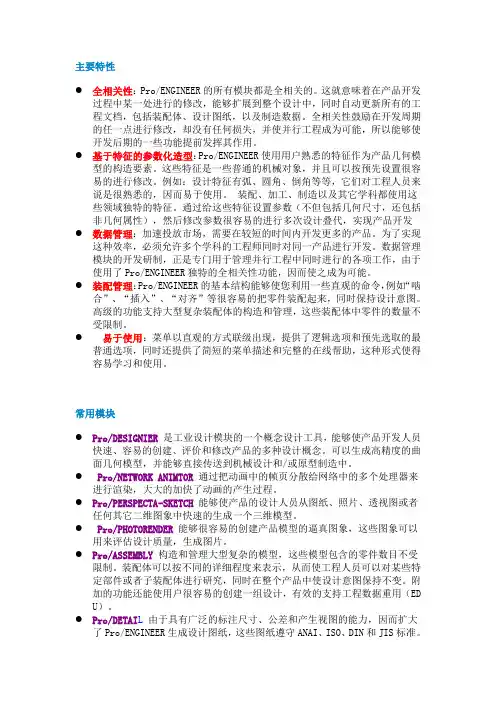
主要特性●全相关性:Pro/ENGINEER的所有模块都是全相关的。
这就意味着在产品开发过程中某一处进行的修改,能够扩展到整个设计中,同时自动更新所有的工程文档,包括装配体、设计图纸,以及制造数据。
全相关性鼓励在开发周期的任一点进行修改,却没有任何损失,并使并行工程成为可能,所以能够使开发后期的一些功能提前发挥其作用。
●基于特征的参数化造型:Pro/ENGINEER使用用户熟悉的特征作为产品几何模型的构造要素。
这些特征是一些普通的机械对象,并且可以按预先设置很容易的进行修改。
例如:设计特征有弧、圆角、倒角等等,它们对工程人员来说是很熟悉的,因而易于使用。
装配、加工、制造以及其它学科都使用这些领域独特的特征。
通过给这些特征设置参数(不但包括几何尺寸,还包括非几何属性),然后修改参数很容易的进行多次设计叠代,实现产品开发●数据管理:加速投放市场,需要在较短的时间内开发更多的产品。
为了实现这种效率,必须允许多个学科的工程师同时对同一产品进行开发。
数据管理模块的开发研制,正是专门用于管理并行工程中同时进行的各项工作,由于使用了Pro/ENGINEER独特的全相关性功能,因而使之成为可能。
●装配管理:Pro/ENGINEER的基本结构能够使您利用一些直观的命令,例如“啮合”、“插入”、“对齐”等很容易的把零件装配起来,同时保持设计意图。
高级的功能支持大型复杂装配体的构造和管理,这些装配体中零件的数量不受限制。
●易于使用:菜单以直观的方式联级出现,提供了逻辑选项和预先选取的最普通选项,同时还提供了简短的菜单描述和完整的在线帮助,这种形式使得容易学习和使用。
常用模块●Pro/DESIGNIER是工业设计模块的一个概念设计工具,能够使产品开发人员快速、容易的创建、评价和修改产品的多种设计概念。
可以生成高精度的曲面几何模型,并能够直接传送到机械设计和/或原型制造中。
● Pro/NETWORK ANIMTOR 通过把动画中的帧页分散给网络中的多个处理器来进行渲染,大大的加快了动画的产生过程。

第一讲
屏幕、内存硬盘中删除
约束:
截面3要素:2D几何图形、尺寸、约束。
要点:1、一般情况下外轮廓(截面)一定要封闭,也就是起点和终点重合。
外轮廓的路径只能有一条。
2、外轮廓中可以嵌套(包含)内轮廓,内轮廓也必须封
闭,并且内轮廓不能和外轮廓相交,内轮廓也不能和
内轮廓相交。
3、内轮廓中不能再嵌套内轮廓,也就是说只能嵌套1层,
不能有1层以上的嵌套,如果多于1层,会不符合逻
辑。
4、外轮廓和内轮廓中也不能有重复的图元。
草图绘制技巧
虽然Pro /E具有捕捉设计者意图和参数化草绘的优点。
但是在草绘时还是应该注意培养一些好的习惯,以便设计中减少错误,降低工作
量,注意以下几点:
1、绘制尺寸大致符合实际的草图,如果绘制的草图在尺寸和形状上大致准确,那么在添加、修改尺寸和几何约束时,草图就不会发生大的变化。
在绘制完第一、第二个元素(图素)时,建议立即修改尺寸,这样,以后的元素就会与已经修改尺寸的元素有一定的参考关系,后面绘制的元素就不会在尺寸上有大的差异,便于草图的绘制。
2、对于重复简单的几何元素,可以先草绘其中一个元素的草图,如何采用复制或阵列的的方法生成其他部分,这样可以减少草图中的几何元素数量。
3、一次绘制的图形不要过于复杂,不要试图一次完成一张复杂图形的绘制,最好分几步进行。
用单一实体对象的草图比用多个对象的草图更便于以后操作,复杂的几何形状可以由简单的实体对象组合而成。
4、采用夸大画法。
绘制小角度时,可以先绘制一个大角度,然后修改成小角度。
因为小角度线系统会自动认为时水平或垂直,导致你绘不出来。

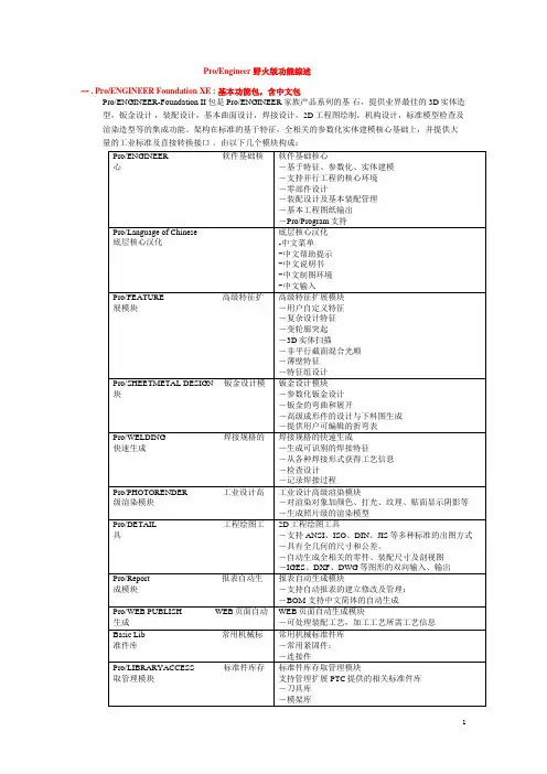
Pro/Engineer 野火版功能综述一 . Pro/ENGINEER Foundation XE : 基本功能包,含中文包Pro/ENGINEER-Foundation II 包是Pro/ENGINEER 家族产品系列的基石,提供业界最佳的3D实体造型,钣金设计,装配设计,基本曲面设计,焊接设计,2D工程图绘制,机构设计,标准模型检查及渲染造型等的集成功能。
架构在标准的基于特征,全相关的参数化实体建模核心基础上,并提供大量的工业标准及直接转换接口。
由以下几个模块构成:Design Animation Option(DAO) —动画设计模块预要求:Pro/Engineer该包使用Pro/E 零件,装配和机构建立动画过程,用于动画演示产品的装卸过程。
Import Data Doctor Option (DDO) —输入数据修补专家预要求:Pro/Engineer该包使用户快速高质量修复调入的第三方模型。
ModelCHECK Option —模型检测模块评估设计效率,提供专家指南。
制定企业标准,在产品设计过程中如有不符合企业标准的设计,软件将自动报警。
同时提供按模型形状索引,搜寻以前设计的形状类似零件,压缩企业零件种类。
Mechanism Design Extension (MDX) —机构运动学分析预要求:Pro/EngineerMDX 提供工程师在产品开发过程中装配体的运动行为模拟和预见。
在装配中,可交互式动态拖动或显式定义模拟过程。
能生成运动过程封装路径用于干涉检查。
二.Advanced Assembly Extension (AAX)预要求:Pro/Engineer-Foundation该包拓展Pro/ENGINEER 的能力到在整个企业开发活动中可设计和管理中到超大型装配。
它提供高级的功能工具进行设计标准管理,自顶向下装配设计,大装配管理,自动模型简化和装配工艺规划。
含以下模块:三. Interactive Surface Design Extension II (ISDXII)预要求:Pro/Engineer-Foundation该包与Pro/ENGINEER-foundation 一起提供中高级复杂产品的设计能力,包含复杂曲面设计。
PRO/ENGINEER 软件模块简介本世纪的一个重大变革是全球市场的统一,它使市场竞争更加激烈,产品更新更快,但是有限的资源加上消费者对复杂产品的需求日益增加,使你合很难保持市场分额。
在这种背景下,CAD( 计算机辅助设计)/CAM( 计算机辅助制造)/CAE (计算机辅助测量)技术得到迅速普及和极大发展。
海湾战争结束当年,美国评出的最具影响的十大技术中,CAD/CAM/CAE 技术便榜上有名。
在为数众多的CAD/CAM/CAE 软件中,主流软件包种类繁多,PRO/E ,UG ,CIMATRON ,MDT ,I -DEAS ,MASTERCAM 都是个中极品,但PRO/E 工业解决方案地位显赫,它是美国PTC 公司的拳头产品,技术领先,在机械、电子、航空、航天、邮电、兵工、纺织等各行各业都有应用,是CAD/CAM/CAE 领域少有的顶尖“人物”。
PRO/E 的最早版本为PRO/E2000i ,它可运行于Windows/NT 和UNIX 平台上,共有六大主模块,下面我把它们逐一介绍给大家。
l PRO/E 概述PRO/ENGINEER 软件包的产品开发环境在支持并行工作,它通过一系列完全相关的模块表述产品的外形、装配及其他功能。
PRO/E 能够让多个部门同时致力于单一的产品模型。
包括对大型项目的装配体管理、功能仿真、制造、数据管理等。
其中PRO/EV2000I 更增加了行为建模技术使其成为把梦想变为现实的杰出工具。
一、工业设计(CAID) 模块工业设计模块主要用于对产品进行几何设计,以前,在零件未制造出时,是无法观看零件形状的,只能通过二维平面图进行想象。
现在,用3DS 可以生成实体模型,但用3DS 生成的模型在工程实际中是“中看不中用”。
用PRO/E 生成的实体建模,不仅中看,而且相当管用。
事实上,PRO/E 后阶段的各个工作数据的产生都要依赖于实体建模所生成的数据。
包括:PRO/3DPAINT(3D 建模) 、PRO/ANIMATE( 动画模拟) 、PRO/DESIGNER( 概念设计) 、PRO/NETWORKANIMATOR( 网络动画合成) 、PRO/PERSPECTA-SKETCH (图片转三维模型)、PRO/PHOTORENDER( 图片渲染) 几个子模块。
proe模块介绍大全Pro/Engineer是一套由设计至生产的机械自动化软件,是新一代的产品造型系统,是一个全参数化、基于特征的实体造型系统,并且具有单一数据库功能。
Pro/E采用了模块方式,可以分别进行草图绘制、零件制作、装配设计、工程图、钣金设计、加工处理等,保证用户可以按照自己的需要进行选择使用。
是现今主流的CAD/CAM/CAE软件之一,特别是在国内产品设计领域占据重要位置。
首先运行proe软件,选择文件---新建,即可出现proe各个模块列表,如下图所示:Pro/Engineer软件各个组成模块介绍:1.Pro/sketch(草绘.sec)二维草绘是Pro/ENGINEER最基本的独立功能模块。
所有的二维图形都是由点、直线、矩形、弧、圆等基本图元构成的,由于Pro/ENGINEER是一款基于特征造型的实体建模软件,各实体模型是由一个个简单的特征累计而成的。
而在创建特征前,往往要先建立二维草绘截面图。
所以,草绘是特征创建的基础,草绘贯穿于实体建模的整个过程,通常是实体造型的第一步。
学会使用这些基本图元的绘制命令可以说是首要之务。
下面列出了关于草绘目的管理器命令的相关内容:2.Pro/part(零件.prt)零件模块分为实体、复合、钣金件、主体、线束五个子模块,常用的就是实体和钣金件两个模块,下面我们针对这两个模块进行详细的介绍。
实体:实体零件是众多的几何特征组合而成,几何特征包括:实体特征、曲面特征、曲线特征及基准特征等,先进的设计特征扩展了Pro/ENGINEER包括下列特征的特征库能力:(l) 壳:产生各种“空心”实体,提供可变壁厚。
(2) 复杂拱形面:生成带有适合不同外形表面的实体模型。
(3) 三维扫描:沿著3D曲线扫描外形以生成雕刻状实体模型。
(4) 薄壁特征:很容易地生成各种“薄壁”特征。
(5) 复杂混和:以一种非平行或旋转的方式(“复画”)将各种外形混合在一起。
(6) 组合零件:将二个零件组台成一个或将一个零件从另一个中去掉形成一个空腔。
Pro/e野火版4.0三维设计Pro/e可以设计零件、建造组件、绘制草图、制作工程图、设计曲面、创建钣金件和交换数据等。
第一章第一章主要介绍功能模块,启动和退出、工作界面、基本的文件操作、视角控制和设置配置文件等选项。
1、功能设计模块:零件设计组件设计二维草绘工程图设计(绘图设计)曲面设计钣金件设计交换数据2、启动和退出:启动是直接双击桌面上的快捷方式或者点击图标按鼠标右键点击开始。
退出是在菜单栏中点击文件中的退出或者点击右上角的X号。
3、工作界面:标题栏、菜单栏、工具栏、导航区、浏览器和图形窗口、信息区与状态栏、选择过滤器。
4、文件的基本操作:新建文件(菜单栏中点击文件-新建,快捷键是Ctrl+N)打开文件保存文件(保存文件时,名称是不能改的,草图保存的时候名称后边显示的是“SEC”,pro/e保存多次的时候不会覆盖上一个文件,如果是找留最新的那张图纸就点击文件-删除-旧版本)拭除文件(就是把当前画的图形删除,在文件-试除-当前)删除文件关闭文件(*注意在保存完文件之后退出的时候一定要先点击文件-试除-当前然后才可以退出,一定要习惯)5、设置工作目录:设计人员一定要养成设计工作目录的习惯,有助于方便管理设计同一设计项目的管理文件。
怎样设置工作目录?先在某个盘里新建一个文件夹,名称不能用中文,然后打开pro/e,点击文件中设置工作目录,然后找到刚新建的那个文件夹,然后确定,在信息区中就会显示成功的改变到刚设置的那个文件夹中,说明就设置成功。
这样是临时目录,当关掉电脑就没有了。
那怎么样设置永久行目录?点击PRO/E快捷图标-右键-点击属性-在找到快捷方式中的起始位置,然后把刚新建立的文件夹位置复制到起始位置中,然后点应用确定。
就可以了。
6、视角操作:把握好视角操作可以提高效率。
要掌握以下视角控制内容:1.视角控制指令2.设置常用的视角3.使用三键鼠标调整视角4.重定向5.旋转中心第二章草绘草绘是建模的基础,养成良好的草绘习惯,注重草绘质量和效率,为三维设计打下基础。
proe功能全介绍(proe功能全介绍)Full introduction of ProE functionPro/ENGINEER is a set of mechanical automation software from design to production, is a new generation of product modeling system, is a parametric, feature-based entity modeling system, and has a single database function.1. parametric design and feature functionPro/ENGINEER is a solid modeling system based on the characteristics of the parametric design, engineering design personnel with intelligent feature based on the function to build the model, such as cavity, shell, and chamfer fillet, you can easily change the sketches, models. This functionality provides engineering designers with simplicity and flexibility that they have never had in their designs.2. single databasePro/ENGINEER is built on a unified base of the database, unlike some traditional CAD/CAM systems built on multiple databases. The so-called single database, that is, all the data in the project from a library, so that each individual user is working for a product modeling, regardless of which department he is. In other words, any change in the entire design process can also be reflected before and after the whole design process related links. For example, the NC (NC) tool path will be updated automatically once the details of the project are changed; the assembly drawings, if any changes, are exactly the same on the whole 3D model. This unique data structure and engineeringdesign of a complete combination, so that a product design combined. This advantage makes the design more optimized, the quality of finished products is higher, the product can be better pushed to the market, and the price is cheaper.One, Pro/ENGINEERPro/ENGINEER is a software package that is not modular. It is the basic part of the system, which features include parameter function definition, entity parts and assembly modeling, 3D solid color or wireframe modeling complete engineering drawings and shed different views (3D modeling can also move, zoom and rotation). Pro/ENGINEER is a function definition system, which is realized through modeling, design of various special functions including: bar (Ribs), slot (Slots) (Cha mfers), chamfering and evacuation (Shells), to establish the physical means for the engineer to say is more natural, more intuitive. Without the use of complex geometric design. This parameter ratio of the system is obtained by using the body size of the symbolic, not like other system is specified directly in the form of some fixed value, so that engineers can be arbitrary to establish the relationship between the size and function of the body, any one of the parameters changes, the relevant features will automatically correct. This function makes the modification more convenient and makes the design optimization more perfect. The shape can not only be displayed on the screen, but also can be sent to the plotter or some color printers that support the Postscript format.Pro/ENGINEER can also output the 2D and 3D graphics to other applications, such as finite element analysis and postprocessing, which is the standard format for data exchange to achieve, users can other modules with the Pro/ENGINEER software or by using the C programming language, to enhance the function of the software. It is in a single user environment (without any additional module) has ability to design most of the assembly capacity (artificial) and engineering drawing ability (not including ANSI, ISO, DIN or JIS), and supports industry standard (HP, HPGL) two-dimensional plotter andblack-and-white and color printers and graphics output.The function of Pro/ENGINEER is as follows:1. feature drive (e.g., boss, groove, chamfer, cavity, shell, etc.);2. parameterization (parameter = size, characteristic of the pattern, load, boundary condition, etc.);3. through the relationship between the parts of the eigenvalue, load / boundary conditions and characteristics of the parameters (such as surface area, etc.) to design.4. supports the design of large and complex assemblies (programmed assemblies, alternately arranged, Pro / PROGRAM programmable procedures for the design of various components).FiveComplete correlation across all applications (any local change will cause any local change associated with it). Other auxiliary modules will further improve the basic functions ofextended Pro / ENGINEER.Two, Pro / ASSEMBLYPro/ASSEMBLY is a parametric assembly management system that provides user defined means to generate a set of assembly sequences and automatically replace parts. Pro/ASSEMBLY is an extended option module for Pro/ADSSEMBLY, which can only run in Pro/E ngineer environment. It has the following functions:1. automatic parts replacement in assembly (alternating type)Combinations of 2. regular permutations (supporting subsets of assemblies)3. component generation in assembly mode (taking into account the existing parts in the component to produce a new part)There is a Pro/Program module in 4.Pro/ASSEMBLY, which provides a development tool. Enables users to write parameterized components and assembly automation programs, which allow not technical users to produce custom designs, simply by inputting some simple parameters.5. component features (drawing parts and adding components toa wide range of components, such as adding a weld feature between two parts).Three, Pro / CABLINGPro/CABLING provides a comprehensive cabling function thatprovides a comprehensive cable laying package for truly designing three-dimensional cables and bundles in Pro/ENGINEER components. The laying of three-dimensional cables can be carried out simultaneously in the design and assembly of electromechanical devices, and it also allows engineering designers to optimize the mechanical and cable space.Pro/CABLING functions include:1. new features include: cables, wires and wires;2. connector design for parts and components;3. the laying of cables, wires and wire bundles on Pro/ENGINEER parts and components;4. generate cable / wire bundle linear length and BOM information;5. generate a three dimensional cable bundle diagram from the components to be laid;6. cable separation and connection for parameter positions;7. calculation of spatial distribution requirements, including interference check;8. cable quality characteristics, including volume, mass, inertia, length;9. specified symbols for plugs and wires.Four, Pro / CATPro / CAT is selected to provide two-way data module, Pro / ENGINEER and CATIA exchange interface, CATIA model can be directly input Pro / ENGINEER software, the function definition and process parameters and adding Pro / ENGINEER, Pro / Engineer can be output to other CATIA software. This highly accurate data exchange technology allows designers to expand investment in existing software systems while saving time and design costs.Five, Pro / CDTPro/CDT is an option module of Pro/ENGINEER, which provides PROFESSIONALCADAM and Pro/ENGINEER two-way data exchange direct interface for CADAM 2D engineering drawing. The files of CADAM engineering drawings can be read directly intoPro/ENGINEER, and can also be output or read into any workstation running Pro/ENGINEER through the PROFESSIONAL CADAM file in a neutral file format. Pro/CDT avoids the problem of exchanging information through standard file format, and enables new customers to continue to enjoy the original CADAM database after they are transferred to Pro/ENGINEER.Six, Pro / CMPOSITEPro/COMPOSITE is an option module for Pro/ENGINEER, which needs to be run with Pro/ENGINEER and Pro/SURFACE. The module can be used to design and composite components of sandwich materials. Pro/COMPOSITE has a complete relevance in the Pro/ENGINEER application environment, the parametric and feature technology provided by this automation tool. It is suitable for every linkof the whole design process.Seven, Pro / DEVELOPPro/DEVELOP is a user development tool,Users can use this software tools to write some of their own or third application software and run in Pro/ENGINEER software environment. Pro/IDEVELOP includes the sub Library of 'C' language, which supports the interface of Pro/ENGINEER and the direct access to Pro/ENGINEER database.Eight, Pro / DESIGNPro/DESIGN can accelerate the design of large and complex sequence of components, these tools can easily generate the assembly hierarchy, assembly concept design of non parametric plane layout, analysis the concept of parametric 2D plane layout and layout of 3D parts. Pro/DESIGN can also assemble parts automatically using 2D plans. It must run in Pro/Engineer environment. Its function is:Connection hierarchy design of 1.3D assembly drawing;2. determination of the size, proportion and datum of the whole and the local;3. case study parametric detailed sketch (2D solver, engineering record and calculation) drawing;4.: assembly allows the use of 3D block components positioningand assembly position;5. automatic assembly.Nine, Pro / DETAILPro/ENGINEER provides the ability for a very wide engineering drawing generation include: automatic dimensioning, parameter feature generation, full size modification, automatic generation of auxiliary projection plane, plane, section and the local view, Pro/DETAIL extends the Pro/ENGI NEER these functions allow directly from the solid modeling ofPro/ENGINEER products according to the standardANSI/ISO/JIS/DIN project figure. The functions supported by Pro/DETAIL include:1. supports ANSI, ISO, JIS and DIN standards;2. geometric tolerance coordination: * characteristic control mark * basic dimension mark * tolerance datum plane and axis;3. measurement standard * mm size * tolerance size * angle dimension4. character high profile * half cutaway * multi exposure control;The 5. variable character height;6. user defined fonts;7. map fonts;8. double size standard;9. longitudinal dimensioning;10. extended view function: * zero component cutaway view * automatic picture view * rotating surface cutaway view * proportional view (all views different proportions) * axonometric drawing (ISO standard); * axonometric drawing (ISO standard);11. mark of surface finish;12. user defined drawing format and drawing format library;13. chart;14. configuration file for setting implicit standard inPro/DETAIL;15. multi lead types for annotating surface finish and star;16. size parallel to dimension line;17. selectable hidden line display observation;18. ASCII file capability with input for annotation;19. multilayer parts drawing and layout.Pro/DETAIL also includes 2D non parametric mapping functions that can be used to generate product diagrams that do not require 3D models. Pro/DETAIL provides the following functions:1. has the ability to read other CAD systems that conform to IGES4.0, SET, and DXF standards.2. has the ability to modify the input graphics to affect design modification or update capability.3. has the ability to manage graphics using Pro/PROJECT to provide graphics storage, restore, and other functions.4. output graphics capabilities with plotters supported by IGES to PTC.5. has the ability to add non relevant geometry to Pro/DETAIL graphics.6. has the ability to generate user-defined symbols and symbol libraries.7. has the ability to generate user defined linetype.。
Pro/E模块全集的介绍(1)proe机械制图英语词汇(一部份)Assembly line组装线Layout布置图Conveyer流水线物料板Rivet table拉钉机Rivet gun拉钉枪Screw driver起子Electric screw driver电动起子Pneumatic screw driver气动起子worktable 工作桌OOBA开箱检查fit together组装在一起fasten锁紧(螺丝) fixture 夹具(治具) pallet栈板barcode条码barcode scanner条码扫描器fuse together熔合fuse machine热熔机repair修理operator作业员QC品管supervisor 课长ME制造工程师MT制造生技cosmetic inspect外观检查inner parts inspect内部检查thumb screw大头螺丝lbs. inch镑、英寸EMI gasket导电条广州有道科技Pro/Engineer是一套由设计至生产的机械自动化软件,是新一代的产品造型系统,是一个参数化、基于特征的实体造型系统,并且具有单一数据库功能。
1.参数化设计和特征功能Pro/Engineer是采用参数化设计的、基于特征的实体模型化系统,工程设计人员采用具有智能特性的基于特征的功能去生成模型,如腔、壳、倒角及圆角,您可以随意勾画草图,轻易改变模型。
这一功能特性给工程设计者提供了在设计上从未有过的简易和灵活。
2.单一数据库Pro/Engineer是建立在统一基层上的数据库上,不象一些传统的CAD/CAM系统建立在多个数据库上。
所谓单一数据库,就是工程中的资料全部来自一个库,使得每一个独立用户在为一件产品造型而工作,不管他是哪一个部门的。
换言之,在整个设计过程的任何一处发生改动,亦可以前后反应在整个设计过程的相关环节上。
例如,一旦工程详图有改变,NC(数控)工具路径也会自动更新;组装工程图如有任何变动,也完全同样反应在整个三维模型上。
这种独特的数据结构与工程设计的完整的结合,使得一件产品的设计结合起来。
这一优点,使得设计更优化,成品质量更高,产品能更好地推向市场,价格也更便宜。
一、Pro/Engineer Pro/Engineer是软件包,并非模块,它是该系统的基本部分,其中功能包括参数化功能定义、实体零件及组装造型,三维上色实体或线框造型棚完整工程图产生及不同视图(三维造型还可移动,放大或缩小和旋转)。
Pro/Engineer是一个功能定义系统,即造型是通过各种不同的设计专用功能来实现,其中包括:筋(Ribs)、槽(Slots)、倒角(Chamfers)和抽空(Shells)等,采用这种手段来建立形体,对于工程师来说是更自然,更直观,无需采用复杂的几何设计方式。
这系统的参数比功能是采用符号式的赋予形体尺寸,不象其他系统是直接指定一些固定数值于形体,这样工程师可任意建立形体上的尺寸和功能之间的关系,任何一个参数改变,其也相关的特征也会自动修正。
这种功能使得修改更为方便和可令设计优化更趋完美。
造型不单可以在屏幕上显示,还可传送到绘图机上或一些支持Postscript 格式的彩色打印机。
Pro/Engineer还可输出三维和二维图形给予其他应用软件,诸如有限元分析及后置处理等,这都是通过标准数据交换格式来实现,用户更可配上Pro/Engineer软件的其它模块或自行利用C语言编程,以增强软件的功能。
它在单用户环境下(没有任何附加模块)具有大部分的设计能力,组装能力(人工)和工程制图能力(不包括ANSI,ISO,DIN或JIS标准),并且支持符合工业标准的绘图仪(HP,HPG L)和黑白及彩色打印机的二维和三维图形输出。
Pro/Engineer功能如下:1.特征驱动(例如:凸台、槽、倒角、腔、壳等);2.参数化(参数=尺寸、图样中的特征、载荷、边界条件等);3.通过零件的特征值之间,载荷/边界条件与特征参数之间(如表面积等)的关系来进行设计。
4.支持大型、复杂组合件的设计(规则排列的系列组件,交替排列,Pro/PROGRAM的各种能用零件设计的程序化方法等)。
5.贯穿所有应用的完全相关性(任何一个地方的变动都将引起与之有关的每个地方变动)。
其它辅助模块将进一步提高扩展Pro/ENGINEER的基本功能。
二、Pro/ASSEMBLYPro/ASSEMBLY是一个参数化组装管理系统,能提供用户自定义手段去生成一组组装系列及可自动地更换零件。
Pro/ASSEMBLY是Pro/ADSSEMBLY的一个扩展选项模块,只能在Pro/Engineer环境下运行,它具有如下功能:1.在组合件内自动零件替换(交替式) 2.规则排列的组合(支持组合件子集) 3.组装模式下的零件生成(考虑组件内已存在的零件来产生一个新的零件) 4.Pro/ASSEMBLY里有一个Pro/Program模块,它提供一个开发工具。
使用户能自行编写参数化零件及组装的自动化程序,这种程序可使不是技术性用户也可产生自定义设计,只需要输入一些简单的参数即可。
5.组件特征(绘零件与,广组件组成的组件附加特征值.如:给两中零件之间加一个焊接特征等)。
三、Pro/CABLINGPro/CABLING提供了一个全面的电缆布线功能,它为在Pro/ENGINEER的部件内真正设计三维电缆和导线束提供了一个综合性的电缆铺设功能包。
三维电缆的铺设可以在设计和组装机电装置时同时进行,它还允许工程设计者在机械与电缆空间进行优化设计。
Pro/CABLING功能包括:1.新特征包括:电缆、导线和电线束;2.用于零件与组件的接插件设计;3.在Pro/ENGINEE R零件和部件上的电缆、导线及电线束铺设;4.生成电缆/导线束直线长度及BOM信息;5.从所铺设的部件中生成三维电缆束布线图;6.对参数位置的电缆分离和连接;7.空间分布要求的计算,包括干涉检查;8.电缆质量特性,包括体积、质量惯性、长度;9.用于插头和导线的规定符号。
四、Pro/CATPro/CAT是选用性模块,提供Pro/ENGINEER与CATIA的双向数据交换接口,CATIA的造型可直接输入Pro/ENGINEER软件内,并可加上Pro/ENGINEER的功能定义和参数工序,而Pro/Engi neer也可将其造型输出到CATIA软件里。
这种高度准确的数据交换技术令设计者得以在节省时间及设计成本的同时,扩充现有软件系统的投资。
五、Pro/CDTPro/CDT是一个Pro/ENGINEER的选件模块,为CADAM 2D工程图提供PROFESSIONALCADA M与Pro/ENGINEER双向数据交换直接接口。
CADAM工程图的文件可以直接读入Pro/ENGINEER,亦可用中性的文件格式,经由PROFESSIONAL CADAM输出或读入任何运行Pro/ENGINEER 的工作站上。
Pro/CDT避免了一般通过标准文件格式交换信息的问题,并可使新客户在转入Pro/ENGINEER后,仍可继续享用原有的CADAM数据库。
六、Pro/CMPOSITEPro/COMPOSITE是一个Pro/ENGINEER的选件模块,需配用Pro/ENGINEER及Pro/SURFACE环境下运行。
该模块能用于设计、复合夹层材料的部件。
Pro/COMPOSITE在Pro/ENGINEER的应用环境里具备完整的关联性,这个自动化工具提供的参数化、特征技术.适用于整个设计工序的每个环节。
七、Pro/DEVELOPPro/DEVELOP是一个用户开发工具,用户可利用这软件工具将一些自己编写或第三家的应用软件结合并运行在Pro/ENGINEER软件环境下。
Pro/IDEVELOP包括…C‟语言的副程序库,用于支援Pro/ENGINEE R的交接口,以及直接存取Pro/ENGINEER数据库。
八、Pro/DESIGNPro/DESIGN可加速设计大型及复杂的顺序组件,这些工具可方便地生成装配图层次等级,二维平面图布置上的非参数化组装概念设计,二维平面布置上的参数化概念分析.以及3D部件平面布置。
Pro/DESI GN也能使用2D平面图自动组装零件。
它必须在Pro/Engineer环境下运行。
其功能有:1.3D装配图的连接层次等级设计;2.整体与局部的尺寸、比例和基准的确定;3.情况研究-参数化详细草图(2D解算器、工程记录和计算)绘制;4.组装:允许使用3D图块表示零组件了定位和组装零件位置;5.自动组装。
九、Pro/DETAILPro/ENGINEER提供了一个很宽的生成工程图的能力,包括:自动尺寸标注、参数特征生成,全尺寸修饰,自动生成投影面,辅助面,截面和局部视图,Pro/DETAIL扩展了Pro/ENGINEER这些基本功能,允许直接从Pro/ENGINEER的实体造型产品按ANSI/ISO/JIS/DIN标准的工程图。
Pro/DETAIL支持的功能包括:1.支持ANSI,ISO,JIS和DIN标准;2.全几何公差配合:* 特征控制标志* 基本尺寸标注* 公差基准面和轴;3.测量标准* 毫米尺寸* 公差尺寸* 角度尺寸4.字符高度控制;5.图内可变字符高度;6.用户自定义字体;7.图内多种字体;8.双尺寸标准;9.纵向尺寸标注;10.扩展视图功能:* 零组件剖视图* 自动画面剖线* 半剖图* 多暴露视图* 旋转面剖视图* 比例视图(所有视图不同比例)* 轴测图(ISO标准);11.表面光洁度标记;12.用户自定义绘图格式和绘图格式库;13.图表;14.用于Pro/DE TAIL设置隐含标准的配置文件;15.用于注释表面光洁度和球星的多引线种类;16.尺寸与尺寸线平行;17.可选择的消隐线显示观察;18.具有输入用于注释的ASCII文件能力;19.多层零件图和布置图。
Pro/DETAIL也包括2D非参数化制图功能,可用于生成不需要3D模型的产品图。
Pro/DETAIL提供下列功能:1.具有读其它符合IGES4.0、SET和DXF标准的CAD系统生成的图形能力。
2.具有修改输入图形来影响设计修改或更新能力。
3.具有利用Pro/PROJECT提供图形储存、恢复等功能来管理这些图形的能力。
4.具有通过IGES到PTC支持的绘图仪输出这些图形能力。
5.具有将非相关性几何体加到Pro/DETAIL图形的能力。
6.具有生成用户自定义的符号和符号库的能力。
7.具有生成用户自定义的线型能力。
十、Pro/DIAGRAMPro/DIAGRAM,是专将图表上的图块信息制成图表记录及装备成说明图的工具。
应用范围遍及电子线体、导管、HVAC、流程图及作业流程管理等。