butterfly valve.pdf(纽威阀门样本NEWAY)
- 格式:pdf
- 大小:2.22 MB
- 文档页数:24

F650HDButterfly Valve with Lug types• Disc 304 stainless steel • Bubble tight shut-off • Resilient seat• Valve face-to-face dimensions comply with API 609 & MSS-SP-67• Completely assembled and tested, ready for installationType overviewType DN F650HD50Technical dataFunctional dataValve size [mm]2" [50]Fluidchilled or hot water, up to 60% glycol Fluid Temp Range (water)-22...250°F [-30...120°C]Body Pressure Rating ANSI Class Consistent with 125, 232 psi CWP Close-off pressure ∆ps 200 psiFlow characteristic modified equal percentage Leakage rate 0% leakage, leakage rate A Servicing maintenance-free Flow Pattern2-way Controllable flow range 90° rotation Cv115 Maximum Velocity 12 FPS Lug threads5/8-11 UNCMaterialsValve body Ductile cast iron ASTM A536Body finish epoxy powder coating (blue RAL 5002)Stem 416 stainless steel Stem seal EPDM (lubricated)SeatEPDMPipe connection for use with ANSI class 125/150 flanges Bearing RPTFEDisc304 stainless steel Gear operator materialsGears - hardened steel Suitable actuatorsNon-Spring ARB(X)GRB(X)SpringAFRB(X)F650HD Product featuresFlow/Mounting detailsDimensionsType DN WeightF650HD50 5.3 lb [2.4 kg]Valve with AFR ActuatorA B C D E F Number of Bolt Holes10.1" [257] 1.8" [45]12.3" [312]9.5" [241] 2.9" [73] 2.9" [73]4Valve with AF/GR N4 ActuatorA B C D E F Number of Bolt Holes14.5" [368] 1.8" [45]16.1" [409]13.3" [338] 3.4" [86] 3.4" [86]4Valve with ARB/GRB ActuatorA B C D E F Number of Bolt Holes14.6" [370] 1.8" [45]12.4" [314]9.7" [246] 2.9" [73] 2.9" [73]4Valve with AFB/AFX ActuatorA B C D E F Number of Bolt Holes10.1" [257] 1.8" [45]15.1" [384]12.4" [315] 2.9" [73] 2.9" [73]4Valve with AMB/AMX ActuatorA B C D E F Number of Bolt Holes8.3" [211] 1.8" [45]15.1" [384]12.4" [315] 2.9" [73] 2.9" [73]4Valve with PR ActuatorA B C D E F Number of Bolt Holes12.0" [304] 1.8" [45]16.7" [425]13.9" [354] 3.9" [100] 3.9" [100]4Valve with PK ActuatorA B C D E F Number of Bolt Holes12.0" [304] 1.8" [45]18.5" [470]15.7" [399] 3.9" [100] 3.9" [100]4A B C D E F Number of Bolt Holes10.8" [275] 1.8" [45]13.0" [330]10.2" [260] 2.9" [73] 2.9" [73]4MFT/programmable, Spring return, 24 VTechnical dataElectrical dataNominal voltageAC/DC 24 V Nominal voltage frequency 50/60 HzNominal voltage rangeAC 19.2...28.8 V / DC 21.6...28.8 V Power consumption in operation 7.5 W Power consumption in rest position 3 W Transformer sizing 10 VAElectrical Connection 18 GA appliance cable, 1 m, with 1/2" NPT conduit connectorOverload Protectionelectronic throughout 0...95° rotation Functional dataOperating range Y 2...10 VOperating range Y note 4...20 mA w/ ZG-R01 (500 Ω, 1/4 W resistor)Input impedance100 kΩ for 2...10 V (0.1 mA), 500 Ω for 4...20 mA, 1500 Ω for PWM, On/Off and Floating point Operating range Y variable Start point 0.5...30 V End point 2.5...32 VOperating modes optional variable (VDC, PWM, on/off, floating point)Position feedback U 2...10 V Position feedback U note Max. 0.5 mA Position feedback U variable VDC variable Direction of motion motor selectable with switchDirection of motion fail-safe reversible with cw/ccw mounting Manual override 5 mm hex crank (3/16" Allen), supplied Angle of rotation 90°Running Time (Motor)150 s / 90°Running time motor variable 70...220 s Running time fail-safe <20 s Adaptation Setting Range off (default)Override controlMIN (minimum position) = 0%MID (intermediate position) = 50%MAX (maximum position) = 100%Noise level, motor 45 dB(A)Noise level, fail-safe 62 dB(A)Position indicationMechanical Safety dataPower source ULClass 2 Supply Degree of protection IEC/EN IP66Degree of protection NEMA/UL NEMA 4XEnclosure UL Enclosure Type 4XAgency ListingcULus acc. to UL60730-1A/-2-14, CAN/CSA E60730-1:02, CE acc. to 2014/30/EU and 2014/35/EUFootnotesDefault/ConfigurationFactory settingsSafety dataQuality Standard ISO 9001Ambient humidity Max. 100% RH Ambient temperature -22...122°F [-30...50°C]Ambient temperature note -40...50°C for actuator with integrated heating Storage temperature -40...176°F [-40...80°C]Servicingmaintenance-free Weight Weight6.7 lb [3.0 kg]MaterialsHousing material Die cast aluminium and plastic casing†Rated Impulse Voltage 800V, Type of Action 1, Control Pollution Degree 2.Product featuresDefault parameters for 2 to 10 VDC applications of the AF..-MFT actuator are assigned during manufacturing. If required, custom versions of the actuator can be ordered. The parameters are variable and can be changed by three means: Factory pre-set or custom configuration, set by the customer using PC-Tool software or the handheld ZTH US.Default parameters for 2 to 10 VDC applications of the AF..-MFT actuator are assigned during manufacturing. If required, custom versions of the actuator can be ordered. The parameters are variable and can be changed by three means: Factory pre-set or custom configuration, set by the customer using PC-Tool software or the handheld ZTH US.AccessoriesGatewaysDescriptionType Gateway MP to BACnet MS/TP UK24BAC Gateway MP to Modbus RTU UK24MOD Gateway MP to LonWorksUK24LON Electrical accessoriesDescriptionType Service tool, with ZIP-USB function, for programmable andcommunicative Belimo actuators, VAV controller and HVAC performance devicesZTH USToolsDescriptionTypeConnecting cable 10 ft [3 m], A: RJ11 6/4 ZTH EU, B: 3-pin Weidmüller and supply connectionZK4-GEN Service tool, with ZIP-USB function, for programmable and communicative Belimo actuators, VAV controller and HVAC performance devicesZTH US Factory add-on option onlyDescriptionType Heater, with adjustable thermostatACT_PACK_HElectrical installationINSTALLATION NOTESActuators with appliance cables are numbered.Provide overload protection and disconnect as required.Actuators may also be powered by DC 24 V.Only connect common to negative (-) leg of control circuits.A 500 Ω resistor (ZG-R01) converts the 4...20 mA control signal to 2...10 V.Control signal may be pulsed from either the Hot (Source) or Common (Sink) 24 V line.For triac sink the Common connection from the actuator must be connected to the Hotconnection of the controller. Position feedback cannot be used with a triac sink controller; theactuator internal common reference is not compatible.IN4004 or IN4007 diode. (IN4007 supplied, Belimo part number 40155).Actuators may be controlled in parallel. Current draw and input impedance must be observed.Master-Slave wiring required for piggy-back applications. Feedback from Master to controlinput(s) of Slave(s).Meets cULus requirements without the need of an electrical ground connection.Warning! Live electrical components!During installation, testing, servicing and troubleshooting of this product, it may be necessaryto work with live electrical components. Have a qualified licensed electrician or other individualwho has been properly trained in handling live electrical components perform these tasks.Failure to follow all electrical safety precautions when exposed to live electrical componentscould result in death or serious injury.Wiring diagramsOn/Off Floating PointVDC/mA Control PWM ControlOverride Control Primary - Secondary。

XLD - Lined Butterfly Valve Series©Copyright 2013 CRANE ChemPharma & Energy 2Ductile Iron, PFA / Teflon ® Lined.ANSI Class 150/PN10 valve design!We listened to our most demanding critics: Our customers. Here‘s our response.3The in-line resilient seal assemblyassures optimum pressure distribution of the body liner to the disc assembly, providing tight sealing under all operating conditions. The wider seal-band provides a broader sealing area.Stem and disc are one simple part combined with the anti-blow-out system. Triple FKM-ring backup-sealsprovide a second, third and fourth line of protection against atmospheric leakage.assures optimum protection of the FKM-rings from corrosive media. These components are located behind the body liner extension. They are isolated Fully lined bottom shaftassures optimum corrosion resistance and eliminates a potential leakage path.You benefit… when experience meets designBody Flange WAFERANSI DIN JIS LUGANSI DIN JISButterfly Valve XLDAll dimensions in inchesAll dimensions in mm45Butterfly Valve XLDDN 50-3002" - 12"DN 350-60014" - 24"DN 50-6002" - 24"6Drilling JIS 10 K (all dimensions in mm)Drilling ANSI Pressure Class 150(all dimensions in inches)Drilling DIN PN 10 / 16 (all dimensions in mm)Flange bolt dimensionsG,H FF: Hole CircleG: Number of Holes/ThreadsH: Diameter of Hole/Thread Dimensionwith latching leverAll Dimensions in mm/inches7 Dimensions with gearDN 50-300, NPS 2" - 12"with gearAll Dimensions in mm/inchesJG9Dimensions with gear DN 350 - 600 NPS 14" - 24"with gearAll Dimensions in mm/inchesHØ EF10Flow CharacteristicsKvalues in m 3/h, C =1.156 KValve coefficients for process control: DN 50-200 / NPS 2-8Valve coefficients for process control: DN 250 - 600 / NPS 10-2411Pressure/Temperature Ratings & Valve TorquesXLD Pressure/Temperature GraphXLD Vacuum/Temperature Graph-20020406080100120140160180200˚C0,000,200,400,600,801,002.95.88.711.614.50.024681012609030120150-43268104140176212248284320356392˚F -20020406080100120140160180200˚CDN 65 NPS 2.5" on request*1 Identical torque at opening and closing, running torque = 40% of break away torque. *2 Max. allowable torque with EN-JS1049O p e r a t i n g P r e s s u r e i n p s iO p e r a t i n g P r e s s u r e i n b a rP r e s s u r e i n b a r aP r e s s u r e i n p s i aC P _E G -X O M O X -X LD -B U -E N -L 15-7-2013-22Crane Co., and its subsidiaries cannot accept responsibility for possible errors in catalogues, brochures, other printed materials, and website information. Crane Co. reserves the right to alter its products without notice, including products already on order provided that such alteration can be made without changes being necessary in specifications already agreed. All trademarks in this material are property of the Crane Co. or its subsidiaries. The Crane and Crane brands logotype, in alphabetical order, (ALOYCO®, CENTER LINE®, COMPAC-NOZ®, CRANE®, DEPA® & ELRO®, DUO-CHEK®, FLOWSEAL®, JENKINS®, KROMBACH®, NOZ-CHEK®, PACIFIC®, RESISTOFLEX®, REVO®, SAUNDERS®, STOCKHAM®,TRIANGLE®, UNI-CHEK®, VALVES®, WTA®, and XOMOX®) are registered trademarks of Crane Co. All rights reserved.brands you trust.XOMOX International GmbH & Co. OHG Von-Behring-Straße 15, D-88131 Lindau/Bodensee Tel.: (49) 8382-702-0Fax. (49) 8382-702-144XOMOX Headquarters 4444 Cooper Road, Cincinnati, OH 45242, U.S.A.Tel.: (513) 745-6000 Fax: (513) 745-6086。

Lightweight, highly reliableand cost-eff ectiveThe Butterfl y Valve 565 comes in the same installation lengthas metal solutions. The exchange does not require any addi-tional work on the pipes or new designs. This reduces the eff ort of both planning and installation, also thanks to a light-er weight.The Butterfl y Valve 565 is built to last. High-performance thermoplastics protect it from abrasion and corrosion. This guarantees a longer system lifetime, even under harsh con-ditions such as water hammers. The results are a reduction of both maintenance costs and production stops. Also in cooling applications the plastic solution has a clear advantage. The condensation is much lower.Thanks to its low weight, a single person can lift and install the Butterfl y Valve 565 in just a few minutes. This also facili-tates planning, since the low weight signifi cantly reduces the need for costly transportation and personnel.Direct ReplacementHighly reliable60% lighterThe new Butterfl y Valve 565 is the best choice for optimizingpiping systems built for water applications and a wide range of other applications. This new generation comes at a signifi -cantly lower initial cost, and will save even more thanks to its lower static weight, requiring less energy for both operation and transportation. Installing the Butterfl y Valve 565 is quick and easy, but thanks to its extremely high durability, it will be almost maintenance-free during its long service life.Plastic Butterfl y Valves have already proven to outperform metal valves in almost every way, thanks to a higher resistance against corrosion and a lighter weight. Now, a new generation has arrived to beat metal in cost-eff ectiveness, too.With its standard interface, the Butterfl y Valve 565 can beupgraded with various modules, such as the smart actuator.This allows for automation and digitization of your systems,making them even more cost-eff ective and effi cient.With the initial cost being comparable to metal solutions, theButterfl y Valve 565 outperforms its metal counterparts in thelong run, reducing maintenance costs, thanks to its superiormaterials and design.Ready for digitizationReduced costsThe Butterfl y Valve 565 is produced by GF Piping Systems inSeewis (Grisons), Switzerland. High-quality valves have beenproduced here for over half a century. They combine techno-logical innovation with the highest standards of material se-lection, manufacturing and quality testing for safety, durabil-ity and reliability.Swiss qualityTo ensure the high quality standard, the butterfl y valves aretested under the toughest conditions in a test stand.VS✓Short installation length✓✓Light weight ✗✓Corrosion resistant ✗✓High p/T performance✓More than half a century ago, GF Piping Systems decided to switch from metal to plastic. This was both a revolutionary and a forward-looking step, as the disadvantages of metal have proven to be the advantages of plastic. The Butterfl y Valve 565 is the newest product of this innovation process, outperforming its metal counterparts in many ways.Butterfl y Valve 565How plastic wins against corrosion and gravityTechnical DataDimension DN50-300, 2" - 12"Pressure rating DN50-150: PN16 / DN200-250: PN10 / DN300: PN6Materials Wafer: fibre reinforced polyamide (PA6-60)Disc: PVDF with fibre reinforced polyamide (PA6.12-GF60)Sealing material EPDM, FKMShaft material Stainless steel, 1.4104 (430 F), Other shaft material on request.Installation length EN558 row 20, ISO 5752 row 20, API 609 table 2Flange standards ISO 7005 PN10/16, EN 1092 PN10/16, DIN 2501 PN10/16, ANSI/ASME B 16.5 Class 150,BS 1560: 1989 Class 125/150; BS 4504 PN10/16, JIS B 2220 10K, JIS B 2239 10K Mounting flange EN ISO 5211Leak test ISO 9393-2, EN 12266 (leak rate A), ISO 5208 (Rate A)Approvals Multiple approvals available on requestActuation variants Manual: lockable hand lever or reduction gear with hand wheel, reduction gear withclamp-on chain wheelPneumatic: FC; FO; DAElectric: AC: 100, 230 V, AC/DC: 24 V, Smart VersionAccessor i es Double sensor for electrical position feedback23475681091Butterfly Valve 565Superior material meets modular designWhen something is built to last, it is all the more important that it can be flexibly adapted to changing requirements. For high-quality plastic materials optimized for durability, modular design is the perfect match. The standard interface also ensures that the Butterfly Valve 565 stays upgradeable during its long lifespan, fit for the ever-evolving future.1Lockable ergonomic lever 2345Optional electric position indicator 876Data-Matrix-Code 10EPDM or FKM sleeve Interface for flexible automation (ISO 5211)Standard 5° ratchet setting 9PVDF discShort installation length Fiber reinforced housing and inner disc Wafer design7Smart actuator for more effi ciency in the work process Electric actuator for highest reliability and ease of usePowered by an electric motor, electrical actuators are highly reliable and very easy to set up and operate. In addition, the latest generation of actuators off ers many intelligent features. Modular accessories such as electric interfaces, integrated battery-powered fail-safe units and visual system feedbackare also available.Pneumatic actuator for reliable operationThe pneumatic actuators are suitable for a wide range of envi-ronments and guarantee high levels of safety and reliability thanks to their fail-safe operation, robust design and high functionality, such as fast cycle times and adjustable travel. They are an economical, functional and reliable solution, espe-cially for installations with a high number of actuated valves.Monitoring by the double sensorThe optional LED position feedback allows the current position of the valve to be centrally recorded and checked at any time – for manually operated and automated valves. The compact dual sensor fi ts even in the most tight areas and is protected against ingress of water and dust.Information via Data-Matrix-Code The Data-Matrix-Code simplifi es the storage of all technical information for each individual valve and thus enables indi-vidual traceability. The faultless identifi cation of each Butterfl y Valve 565 facilitates easy installation, service and repair.Modular process automationFind out more/565Reduction gear with handwheelThe smart actuator makes full use of the possibilities of digiti-zation: Thanks to the app, you can access it at any time in order to read data or carry out settings, for example. This makes work easier and more effi cient than ever before. The reduction gear with handwheel allows reliable, manual operation of the Butterfl y Valve 565. Worm gears ensure that only minimal physical eff ort is required. They can fully open and close and are useful for high-stress situations.GF Piping SystemsThe information and technical data (altogether “Data”) herein are not binding, unless explicitly confirmed in writing.The Data neither constitutes any expressed, implied or warranted characteristics, nor guaranteed properties or a guaranteed durability. All Data is subject to modification. The General Terms and Conditions of Sale of Georg Fischer Piping Systems apply.Worldwide at homeOur sales companies and representatives ensure local customer support in more than 100 Argentina / Southern South AmericaGeorg Fischer Central Plastics Sudamérica S.R.L.Buenos Aires / Argentina Phone +54 11 4512 02 90gfcentral.ps.ar@georgfi /arAustraliaGeorge Fischer Pty Ltd Riverwood NSW 2210Phone +61 (0) 2 9502 8000 australia.ps@georgfi /auAustriaGeorg Fischer Rohrleitungssysteme GmbH 3130 HerzogenburgPhone +43 (0) 2782 856 43-0austria.ps@georgfi /atBelgium / Luxembourg Georg Fischer NV/SA1600 Sint-Pieters-Leeuw / Belgium Phone +32 (0) 2 556 40 20Fax +32 (0) 2 524 34 26be.ps@georgfi /beBrazilGeorg Fischer Sist. de Tub. Ltda.04571-020 São Paulo/SP Phone +55 (0) 11 5525 1311br.ps@georgfi /brCanadaGeorg Fischer Piping Systems Ltd Mississauga, ON L5T 2B2Phone +1 (905) 670 8005Fax +1 (905) 670 8513ca.ps@georgfi /caChinaGeorg Fischer P iping Systems Ltd Shanghai 201319Phone +86 21 3899 3899 china.ps@georgfi /cnDenmark / Iceland Georg Fischer A/S2630 Taastrup / Denmark Phone +45 (0) 70 22 19 75info.dk.ps@georgfi /dkFinlandGeorg Fischer AB 01510 VantaaPhone +358 (0) 9 586 58 25 Fax +358 (0) 9 586 58 29info.fi.ps@georgfi /fiFranceGeorg Fischer SAS95932 Roissy Charles de Gaulle Cedex Phone +33 (0) 1 41 84 68 84fr.ps@georgfi /frGermanyGeorg Fischer GmbH 73095 AlbershausenPhone +49 (0) 7161 302 0info.de.ps@georgfi /deIndiaGeorg Fischer Piping Systems Pvt. Ltd 400 083 MumbaiPhone +91 22 4007 2000 Fax +91 22 4007 /inIndonesiaPT Georg Fischer Indonesia Karawang 41371, Jawa Barat Phone +62 267 432 044Fax +62 267 431 857indonesia.ps@georgfi /idItalyGeorg Fischer S.p.A.20864 Agrate Brianza (MB)Phone +39 02 921 86 1Fax +39 02 921 86 24 7 it.ps @georgfi /itJapanGeorg Fischer Ltd 530-0003 OsakaPhone +81 (0) 6 6341 2451jp.ps@georgfi /jpKoreaGeorg Fischer Korea Co. Ltd Unit 2501, U-Tower120 Heungdeok Jungang-ro (Yeongdeok-dong)Giheung-gu, Yongin-si, Gyeonggi-do Phone +82 31 8017 1450Fax +82 31 217 1454kor.ps@georgfi /krMalaysiaGeorge Fischer (M) Sdn. Bhd.41200 Klang, Selangor Darul Ehsan Phone +60 (0) 3 3122 5585Fax +60 (0) 3 3122 5575my.ps@georgfi /myMexico / Northern Latin America Georg Fischer S.A. de C.V.CP 66603 Apodaca, Nuevo León / Mexico Phone +52 (81) 1340 8586Fax +52 (81) 1522 8906mx.ps@georgfi /mxMiddle EastGeorg Fischer Piping Systems (Switzerland) Ltd Dubai / United Arab Emirates Phone +971 4 289 49 60gcc.ps@georgfi /intNetherlandsGeorg Fischer N.V.8161 PA EpePhone +31 (0) 578 678 222 nl.ps@georgfi /nl New Zealand Georg Fischer Ltd 5018 Upper HuttPhone +04 527 9813Fax +04 527 9834nz.ps@georgfi /nz NorwayGeorg Fischer AS 1351 RudPhone +47 67 18 29 00no.ps@georgfi /no PhilippinesGeorge Fischer Pte. Ltd.1500 San Juan City Phone +632 571 2365Fax +632 571 2368sgp.ps @georgfi /sgPolandGeorg Fischer Sp. z o.o.05-090 Sekocin NowyPhone +48 (0) 22 31 31 0 50 poland.ps@georgfi /plRomaniaGeorg Fischer Piping Systems (Switzerland) Ltd 020257 Bucharest - Sector 2Phone +40 (0) 21 230 53 80ro.ps@georgfi /intRussiaGeorg Fischer Piping Systems (Switzerland) Ltd Moscow 125040Phone +7 495 748 11 44ru.ps@georgfi /ruSingaporeGeorge Fischer Pte Ltd 528 872 Singapore Phone +65 6747 0611Fax +65 6747 0577sgp.ps@georgfi /sgSpain / Portugal Georg Fischer S.A.28046 Madrid / SpainPhone +34 (0) 91 781 98 90es.ps@georgfi /esSwedenGeorg Fischer AB 117 43 StockholmPhone +46 (0) 8 506 775 00info.se.ps@georgfi /seSwitzerlandGeorg Fischer Rohrleitungssysteme (Schweiz) AG Phone +41 (0) 52 631 3026ch.ps@georgfi /chTaiwanGeorg Fischer Co. LtdSan Chung Dist., New Taipei City Phone +886 2 8512 2822Fax +886 2 8512 /twUnited Kingdom / Ireland George Fischer Sales LimitedCoventry, CV2 2ST / United Kingdom Phone +44 (0) 2476 535 535uk.ps@georgfi /uk USA / Caribbean Georg Fischer LLC 92618 Irvine, CA / USA Phone +1 714 731 8800 Fax +1 714 731 6201us.ps@georgfi /us VietnamGeorge Fischer Pte Ltd Ho Chi Minh CityPhone + 84 28 3948 4000Fax + 84 28 3948 4010sgp.ps@georgfi /vnInternationalGeorg Fischer Piping Systems (Switzerland) Ltd Phone +41 (0) 52 631 3003Fax +41 (0) 52 631 2893info.export@georgfi /intGFDO_BR_00045_EN (10.21)700.671.702。

Cat.no.:E-BFVCat.no.:E-PVCat.no.:E-CSV Cat.no.:E-PS Cat.no.:E-FSVCat.no.:E-PLVNo.999 Xiangjiang Road, Suzhou New District,P .R. China Post Code:215129Tel: 86-512-666-51365Fax: 86-512-666-51360E-Mail: neway@ C a t .n o .:E -P V -2005-U S12315 Parc Crest Drive Suite 190Stafford, T exas 77477Phone: 281-933-5775Fax: 281-933-5779JAG Flocomponents USA, Ltd.U.S. Sole Distributor:Manufacturer:Cat.no.:E-MVN the safety and protection ofe w a y r e c o g n i z e s t h eimportance of valve quality for personnel health and property. It is our quality commitment to focus our resources to provide our customers with first class products at a competitive price, that are designed, manufactured, inspected and tested in accordance with our customers, specifications and that comply with all international standards.With respect to the facts that the current industrial standards do not always take into consideration the likelihood and consequences of possible deterioration in service, related to specific service fluids or the external environment in which they operate. Our customers are requested to keep an open line of communication withNEWAY technical research center utilizes the most advanced computertechnology to improve the existing products and develop the new lines, this includes a highly educated and trained engineering team and a comprehensive internal computer network which links the entire operations of design, manufacturing and administration.NEWAY design philosophy is to develop a safety and cost-efficient valve, we introduced the latest AUTO CAD and I-DEAS software for all our new product design research which include the advanced finite element analysis to virtually verify the new design prior to production, this has resulted in dramatically reducing the new product design time and ensure a safety and cost efficient final product.NEWAY technical personnel are always ready to offer on line or on site technical training and support for all of its distributors, agents and end users.Fire safe is standard design of all NEWAY ball valve.Technical InnovationAPI 6D API 607API 6FA BS 5351BS 6755ANSI B16.34ANSI B16.10ANSI B16.5MSS SP-25MSS SP-55 NACE Std MR0175SHELL MESCAPI 598 Fire Safe Test CertificateTest FacilityTest ChartCNC LatheThe latest computer technology are also widely applied in NEWAY for valve manufacturing, this include a large number of numeric control machines (Machining center, CNC horizontal and vertical lathe, CNC drilling machine) and ERP management system which significantly improve our machining quality and process control. NEWAY also employes a number of conventional lathe with capacity up to machine 48ball valve.NEWAY manufacturing philosophy is to ensure stable quality and just in time delivery.4.2M Lathe CNC Lathe Automatic welding MachineMachining CenterCNC DrillingNEWAY developed an extensive and advanced inspection and test facilities to control the quality from rough castings or forgings to final products. These facilities enable us to do Radio graphic test, Ultra-sonic test, Dye-penetrate test, Magnetic test, Positive Material Identifier (PMI), Impact test, T ensile test, Hardness test, Fire safe test, Cryogenic test, Vacuum test, Low fugitive emission test and Hydro-static test.NEWAY Quality Assurance is dedicated to the pursuit of a zero defect valve, and this has resulted in the company having more quality qualifications and end user approval than most of our competitors. NEWAY is certified by ISO 9001 (certificate under DNV) and API 6D (registered no. 6D-0285) and our off-shore platform valves are type approved by ABS. Moreover, NEWAY is the first valve manufacturer in China to be certified to CE/PED (category IV, mode B+D, certificate under B.V.), All of NEWAY soft seated ball valves are fire safe tested and certified by Lloyd s Register.Part number identificationControlled Stem & Stuffing Box FinishFor the elimination of air pollution, it is essential to control the fugitive emissions leakage of various chemicals from valves in your chemical plant. NEWAY low emissions ball valves installed with our emissions defense packing have been designed and tested to m e e t t h e 100 P P M m a x i m u m e m i s s i o n l e v e l (acceptance test per Shell SPE 77/312). This is NEWAYstandard specification for all series BA, B and BB flanged floating ball valve.The stem surface finish is controlled between Weather proofbelleville-spring washerLow Emission packingFire Safe Seat SealingAdditionally, the fire safe metal seat can prevent the line pressure erosion on soft seat and minimize soft seat creep deformation. All NEWAY floating valves fire safe is designed and test certified in accordance with API 607.When static are generated and concentrated on the ball, the spring-loaded pins installed on ball, stem are provided to ensure electrical continuity throughout the valve.Anti-Static DeviceStem lower end is integral T shaped designed to be blow-out proof. It is internally inserted and functions as the backseat for assured stem sealing at all pressuresBlow-out Proof StemBefore FireBodyStemPacking ClosureBall StemPackingBallSeatBodyPackingStemAnti-Static DeviceClosureBodyBallGasketClosureWhen non-metal sealing material are decomposed or deteriorated by a plant fire, the upstream line pressure pull the ball into contact with the metal seat lip beneath the soft seat to shut off the line fluid to minimize the internal leakage.Design Feature:Live Loaded Gland FlangeLow Emission PackingLive loading is designed to provide gland load retention, compensating for expected in-service consolidation of the packing. A set of Belleville-Spring Washers are used on each gland stud to help exert a continuous compressive force on the gland follower flange and therefore reduce fugitive emissions from the stem packing. NEWAY standard Belleville-Spring Washers are protected by a weatherproof cap to keep them free from environmental contamination, resulting in a longstable life.The packing set is a combination of parallel and vertical layer sealing elements, which are made of expanding graphite in die-formed rings and have features of heat resistance, less stress relaxation and low creep. With this special structure, it allows for a low-friction on rotary & rising stem valves, therefore providing the stabilized seal performance for long cycle life.For medium and low temperature service, the standard V shape PTFE packing rings are installed for lowemission control.Floating Ball Valve Design FeatureLow Emission Control2963161861171514128137541110Series FE1 Ball ValveRegular port, uni-body, end entry designBlow-out Proof StemInternally inserted and functions as the backseat for assured stem sealing at all pressuresMetal-to-Metal Sealing When non-meatl sealing is deteriorated by fire,ball floats to shut off the line fruidEmission-free Graphite primary gasketIndex noPart123456789Index no PartBody Closure BallGland Flange Lever Seat Ring Stem Gland Gasket101112131415161718Grounding Washer Packing Set Stop Plate Thrust Washer Retainer Washer Bolt Rotaining SpringSeries FE1 Ball ValveSeries FE1 Ball ValveRegular port,uni-body,cast steel,end entry designClass 150LBWeight KgW mmH mmL mmD mmd mmSizeinDimensionsWW DLdHWDLddHGear Operator1 / 22 3101 / 23 / 411-1/222-1/23468101 / 23 / 49.512.71930385164761141441879.512.712.71925.43851647610215220325412.719108117127165178191203229267292330140152545964901021121211662082463035459120140140160265265265300400 300 * 400 *120140 1.72.72.985.008.7112.416.6624.38541011502.83.61638111071817962416135151412Series FB2 Ball Valveavailable in size from to 12 full port or witnessed and certified by Lloyd s Register.Double "D" Stem HeadProvides mounting of the lever handle alwaysin parallel to the flow passage Blow-out Proof Stem Internally inserted and functions as the backseat for assured stem sealing at all pressuresEmission-free Graphite primary gasket Metal-to-Metal SealingWhen non-meatl sealing isdeteriorated by fire,ball floats to shut off the line fruid easily for installation of gear, motor or pneumatic actuator 123456789Body Closure Ball Yoke Gland Flange Seat Ring Stem Gland Gasket 101112131415161718Grounding Washer Packing Set Thrust Washer Stud Nut Bolt Bolt Spring Steel BallSeries FB2 material specifications Series FB2 Ball Valve Two-piece,split body,cast steel,side entry design Full Port Size in D mm L mm H mm W mm Weight Kg Reduced Port Size in D mm L mm H mm W mm Weight Kg d mm 150L B Gear Operator Dimensions W H D L Full Port WH d D L Reduced Port W 123456789101112131415161718No. Part Standard Stainless Steel Sour Service Low TemperatureServiceASTM A352-LCB ASTM A352-LCB ASTM A182-F316ASTM A216-WCB ASTM A216-WCB PTFE ASTM A182-F316ASTM A182-F316316SS + Graphite Graphite PTFE PTFE ASTM A320-L7M ASTM A194-7M ASTM A320-L7M ASTM A320-L7M S.S.S.S.ASTM A216-WCB ASTM A216-WCB ASTM A105/ENP ASTM A216-WCB ASTM A216-WCB PTFE ASTM A182-F6a ASTM A276-420316SS + Graphite Graphite PTFE PTFE ASTM A193-B7M ASTM A194-2HM ASTM A193-B7M ASTM A193-B7M S.S.S.S.ASTM A351-CF8M ASTM A351-CF8M ASTM A182-F316ASTM A351-CF8M ASTM A351-CF8M PTFE ASTM A182-F316ASTM A182-F316316SS + Graphite Graphite PTFE PTFE ASTM A193-B8ASTM A194-8ASTM A193-B8ASTM A193-B8S.S.S.S.ASTM A216-WCB ASTM A216-WCB ASTM A105/ENP ASTM A216-WCB ASTM A216-WCB PTFE ASTM A182-F6a ASTM A276-420316SS + Graphite Graphite PTFE PTFE ASTM A193-B7ASTM A194-2H ASTM A193-B7ASTM A193-B7S.S.S.S.Body Closure Ball Yoke Gland Flange Seat Ring Stem Gland Gasket Grounding Washer Packing Set Thrust Washer Stud Nut Bolt Bolt Spring Steel Ball 1 / 23 / 411-1/222-1/23456810121 / 2131925385164761021251522032543051310811712716517819120322935639445753361014059637697107142152178252272342345479591301301602302304004007001100 300 * 300 * 400 * 600 *1303/4*1/2*3/43/4*1/2*3/41*3/4*11-1/2*1-1/22*1-1/2*22-1/2*2*2-1/23*2-1/2*34*3*46*4*68*6*810*8*1012*10*121.782.003.517.2311.0515.022.036.058.0110.0195.0309.0346.02.29131925385164761021522032541319253851647610215220325430519117127165178190203229394457530610152828510011512015316219129034044282130130160230230400400460 300 * 300 * 400 *130 3.04.57.09.515.016.029.548.0123.0212.0230.03.5Series FB2 Ball Valve122019178111354197161021181631415296Blow-out Proof Stem Internally insertedand functions as the backseat for assured stem sealing at all pressuresSeries FB2 Ball Valve Two-piece, split body, forged steel, side entry design This series ball valves are featured with two-piece bolted with flanged end body and floating ball. Body and closure are fully forged steel made which eliminate the inevitable casting defects and is ideal for high pressure service. FB2 series ball valves are available in size from 1 /2 to 4 and offers ANSI class rating 600 to 2500, all meet the fire safe requirements of BS 6755 and API 607. Blowout-proof stem, anti-static device and locking device are standard design, low emission packing with live loaded gland flange design can be available upon request. Manual handle operation is basic standard, but fully machined mounting pad can also easily install with gear, motor or pneumatic operator.ANSI Class 150 to 300 and Three-piece design can be supplied upon request.Double "D" Stem HeadProvides mounting of the lever handle always in parallel to the flow passageSecure LIne Flow Equipped with an integral locking device to secure the line flow Spring-loaded pins installed on ball, stem is provided to ensure electrical continuity throughout the valve Bolted Body/AdapterFlanged body and flanged adapter secured with cap screws to maintain seal integrity Metal-to-Metal SealingWhen non-meatl sealing is deteriorated by fire,ball floats to shut off the line fruid Index no Part 1234567891011Body Closure Ball Lever Lever Sleeve Seat Ring Stem Gland Gasket Steel Ball Packing Set Index no Part 12131415161718192021Stop Plate Thrust Washer Stud NutSpringSpring Washer Stop Pin Nut WasherLocking Plate Series FB2 Ball ValveThis is a typical Series FB2 floating ball valve illustrated cross-section drawing which is only fordemonstrating of basic design features. The actual product design may be slightly different from this sample drawing due to its size and pressure class.Series FB2 material specifications Series FB2 Ball Valve 123456789101112131415161718192021No. Part Standard Stainless Steel Sour Service Low TemperatureServiceBody Closure Ball Lever Lever Sleeve Seat Ring Stem Gland Gasket Steel Ball Packing Set Stop Plate Thrust Washer Stud Nut Spring Spring Washer Stop Pin Nut Washer Locking Plate ASTM A105ASTM A105ASTM A105/ENP Carbon Steel Polyethylene PTFE ASTM A182-F6a ASTM A276-420Graphite S.S.PTFE Carbon Steel PTFE ASTM A193-B7M ASTM A194-2HM S.S.Alloy Steel Carbon Steel Carbon Steel Carbon Steel Carbon Steel ASTM A350-LF2ASTM A350-LF2ASTM A182-F316Carbon Steel Polyethylene PTFE ASTM A182-F316ASTM A182-F316316 + Graphite S.S.PTFE S.S.PTFE ASTM A320-L7M ASTM A194-7M S.S.Alloy Steel S.S.S.S.S.S.S.S.ASTM A182-F316ASTM A182-F316ASTM A182-F316Carbon Steel Polyethylene PTFE ASTM A182-F316ASTM A182-F316Graphite S.S.PTFE S.S.PTFE ASTM A193-B8ASTM A194-8S.S.Alloy Steel S.S.S.S.S.S.S.S.ASTM A105ASTM A105ASTM A105/ENP Carbon Steel Polyethylene PTFE ASTM A182-F6a ASTM A276-420Graphite S.S.PTFE Carbon Steel PTFE ASTM A193-B7ASTM A194-2H S.S.Alloy Steel Carbon Steel Carbon Steel Carbon Steel Carbon Steel Two-piece,split body,forged steel,side entry design L W H D H Dd WL Dimensions Full Port Size in D mm L mm H mm W mm Weight Kg Reduced Port Size in D mm L mm H mm W mm Weight Kg d mm 600L B B Full Port Reduced Port 3/4*1/2*3/4713131921622970831401707.510.01/2*1/4*1/21 / 23 / 41319216229831121701708.511.01 / 23 / 411-1/2234131925385176102165191216241292356432668890120135180224160170170280300450500 3.55.16.513.229.034.0135.53/4*1/2*3/41*3/4*11-1/2*1*1-1/22*1-1/2*23*2*3713192538517613192538517610216519121624129235643243668890120135180130160170170280300450 2.93.85.310.61342.081.51/2*1/4*1/24*3*4Series FB2 Ball ValveSeries FB2 Ball Valve Series BC Ball Valve Two-piece,split body,forged steel,side entry designL W HD WLHDd DimensionsFull Port Size in D mm L mm H mm W mm Weight Kg Reduced PortSizein D mm L mm H mm W mm WeightKgd mm150LBFull Port Reduced Port1 / 23 / 411-1/22313192538517621622925430536847083112123143177200230230300400450700 6.811.016.032.664.090.0713264751708.01/2*1/4*1/21 / 213264882309.03/4*1/2*3/41*3/4*11-1/2*1*1-1/22*1-1/2*23*2*37131925385113192538517621622925430536847070831121231431771702302303004004507.510.015.028.041.082.01/2*1/4*1/2NEWAY trunnion mounted ball valve contains 3 main series: TB2 series for cast steel two-piece design, TB3 series for forged steel three-piece design and TTE series for top entry uni-body design, all designed conform to API 6D and fire safe test are satisfied to BS 6755 and API 6FA. They are available in size from 2to 48Wide range of body and trim material is available for service00temperature from -46C to 200C and pressure rating from ANSI class 150 to 1500 or for sour service to NACE Mr0175.For 6 inch and larger NEWAY Trunnion mounted ball valveswill be installed with a sealant injection fittings on both stemand seats. When the sealing materials (seat sealing or stemo-ring) are damaged or decomposed by fire or otheraccidental causes, leakage from the seat and stem can beprevented by injection of sealant into these fittings. Fitting isalso internally installed a second check valve to providesbackup sealing. Emergency sealant injection system Cavity Pressure ReliefEach ball seats shut off the line fluid independently on the upstream and downstream side, allowing double block o p e r a t i o n. W h e n t h e p r e s s u r e i s simultaneously applied to both sides of the ball in closed position, the valve bore and the body cavity will be isolated from each other, and the residue within the body cavity can be released through the drain plug.Double block and bleed Top flange Injection Closure Gland Body Ball SeatThe stem is made separately from the ball; The lover end of the stem is designed with an integral collar to be blowout-proof.Antistatic device is a standard feature of NEWAY ball valve . A spring-loaded pin assures the electrical continuity, between ball ,stem and body, so as to avoid sparks during turning of the stem to open and close the valve, which could be dangerous in caseof hazardous area installation.Super Fire safe designExternal leakage preventionLeakage from the valve stem area isprevented by double sealing with 2 O-rings and gland gasket. Leakagethrough the valve body joint is alsoblocked by double sealing with O-ringand body gasket. After a fire hasdeteriorated O-rings, gland gasket,body gasket and stem firesafe packingare the measure that prevents externalfluid leakage. When non-metal materials such as O-ring, seat insert and spacer aredecomposed or deteriorated by fire, theedge of the metal seat preloaded by theBall to shut off the line fluid to minimize internal leakage through the valve bore. Also the fire safe flexible graphite seat packing will be compressed by the seat spring to prevent fluid leakage Internal leakage preventionAnti Blow-out Stem Anti-static Device Top Flange Stem Stem fire safe packingGland O-ring Gland gasket Body Ball Anti-static spring Grounding plunger Drain plug Body Upstream seat Body cavity Closed ball Vent valve Downstream seat Body cavity Total spring force (Fs)Cavity pressure (Pc)Fig b. P*D1>FsP=Pc-Pl Cavity pressure (Pc)Total spring force (Fs)Fig a. P*D1<Fs P=Pc-Pl Stem Top Flange Gland Body Closure O-ring Ball Gland gasket Body gasket Stem firesafe packing Trunnion Mounted Ball ValveDesign FeatureTrunnion Mounted Ball Valve Design FeatureH L Dd W H L D d d mm L mm H mm W mm D mm L mm H mm W mm d mm 517610215220325430533738743843848976102152203254305337387438489540591203229394457533610686762864914101610671651932313293933934414815986436437082304004004601000*500*500*500*500*500*500*500304790161268467560766902113013001520234681012141618202224517610215220325430533738743848954059125121616523018178203229394457533610686762864914101610671651932313293934014414815986437087988632304004601000*500*500*500*500*500*500*500*500*500173350931662734755707789351190134615795176283165230383*2*34*3*46*4*68*6*810*8*1012*10*1214*12*1416*14*1618*16*1820*18*2022*20*2224*20*243*2*3WD mm L mm H mm W mm D mm L mm H mm W mm d mm 51761021522032543053373874384897610215220325430533738743848959135643255966078783888999110921194139717624727636336342654859864874081040075010001500*500*500*500*500*500*500*5004170122255440662010601440186024003240 600L B 234681012141618202451761021522032543053373874384895912351763683811922794601000529729235643559660787838889991109211941397217624727636336342654859864874081092040075010001500*500*500*500*500*500*500*500*500275080251.835060082011301550210028003626517676102381457192279460100083103--------------3*2*34*3*46*4*68*6*810*8*1012*10*1214*12*1416*14*1618*16*1820*18*2024*20*243*2*34*3*4W HL D d L H D d WTwo-piece,split body,cast steel,side entry design Full PortSizeinWeight Kg Reduced Port Size in Weight Kg DimensionsGear Operator Series TB2 Ball Valve Series TB2 Ball ValveTow-piece,split body,cast steel,side entry design Gear OperatorFull Port Size in Weight Kg Reduced Port Size in Weight Kg Dimensions 150L BWDdHWDdHLL22328201315652919810383733341426161127918363538724251221173231302230311Series TB3 Ball ValveIndex noPart12345678910111213141516171819Body Closure BallSeat Assembly( )Seat Insert Seat Ring StemTrunnion Alignment Pin ShimTrunnion Support Gasket Body Gasket Spacer GasketFiresafe Gasket Gland Cap Top Flange Thrust Washer BearingIndex noPartSeat Follower Vent Valve Drain Seat Spring Grounding Spring Grounding Plunger O-Ring O-Ring O-Ring Series TB3 Ball ValveD mmL mmH1mm2346810121416182022242651761021522032543053373884384895405916351782032293944575346106867628649149911067114320030031533540542746550662266673083389590011012616516520022026229334192435480518535265285285*300*300*300*500*600*600*600*600*600*800*80021.1132.0992190345495577859114414401918235228033200W mmH2mmSize inD mmL mmH1mmW mm3*2*34*3*46*4*68*6*810*8*1012*10*1214*12*1416*14*1618*16*1820*18*2022*18*2224*20*2426*22*2628*24*28d mm517610215220325430533738743843848954059176102152203254305337387438489540591635686203229394457534610686762864914991106711431245200300315335405427465506622666666730833895110126165170200220262293341392392435480518265285285*300*300*300*500*600*600*600*600*600*600*80026.4540102225373509730790109511522343206022152700H2mmWH 1H 2DdWLSeries TB3 Ball ValveSeries TB3 material specifications 123456789101112131415161718192021222324252627No. Part Standard Stainless Steel Sour Service Body Closure BallSeat Assembly Seat Insert Seat Ring Stem Trunnion Alignment Pin ShimTrunnion Support Gasket Body Gasket Spacer Gasket Firesafe Gasket Gland Cap Top Flange Thrust Washer Bearing Seat Follower Vent Valve Drain Seat Spring Grounding Spring Grounding Plunger O-Ring O-Ring ASTM A105ASTM A105ASTM A105/ENPAssembled By No.5&625% Glass-filled PTFE ASTM A105/ENP ASTM A105/ENP ASTM A182-F316ASTM A182-F316ASTM A216-WCB/ENP 316SS + Graphite 316SS + Graphite PTFE316SS + Graphite 316SS + Graphite ASTM A105ASTM A105316 + PTFE + MoS2316 + PTFE + MoS2ASTM A105/ENP Assembly S.S.Inconel X-750S.S.ASTM A182-F316NBR NBR ASTM A182-F316ASTM A182-F316ASTM A182-F316Assembled By No.5&625% Glass-filled PTFE ASTM A182-F316ASTM A182-F316ASTM A182-F316ASTM A182-F316ASTM A351-CF8M 316SS + Graphite 316SS + Graphite PTFE316SS + Graphite 316SS + Graphite ASTM A182-F316ASTM A182-F316316 + PTFE + MoS2316 + PTFE + MoS2ASTM A182-F316Assembly S.S.Inconel X-750S.S.ASTM A182-F316NBR NBR ASTM A105ASTM A105ASTM A105/ENPAssembled By No.5&625% Glass-filled PTFE ASTM A105/ENP ASTM A105/ENP ASTM A182-F316ASTM A182-F316ASTM A216-WCB/ENP 316SS + Graphite 316SS + Graphite PTFE316SS + Graphite 316SS + Graphite ASTM A105ASTM A105316 + PTFE + MoS2316 + PTFE + MoS2ASTM A105/ENP Assembly S.S.Inconel X-750S.S.ASTM A182-F316NBR NBR ASTM A350-LF2ASTM A350-LF2ASTM A350-LF2/ENPAssembled By No.5&625% Glass-filled PTFE ASTM A350-LF2/ENPASTM A350-LF2/ENP ASTM A182-F316ASTM A182-F316ASTM A352-LCB/ENP316SS + Graphite 316SS + Graphite PTFE316SS + Graphite 316SS + Graphite ASTM A350-LF2ASTM A350-LF2316 + PTFE + MoS2316 + PTFE + MoS2ASTM A350-LF2/ENP Assembly S.S.Inconel X-750S.S.ASTM A182-F316NBR NBR Low TemperatureServiceDimensionsClass 150LB Full PortSize inWeight KgClass 150LB Reduced portWeight KgGear OperatorThree-piece,split body,forged steel,side entry designD mmL mmH1mm234681012141618202224285176102152203254305337388438489540591686292356432559660787838889991109211941295139715492063153303454154274655196386837488549179581131291691481852262693003504024464925315564007501000*300*300*500*600*600*600*600*600*800*800*8003363.5117273.54527366251230153521352640337049206060W mmH2mmD mmL mmH1mmW mm3*2*34*3*46*4*68*6*810*8*1012*10*1214*12*1416*14*1618*16*1820*18*2022*18*2224*20*2428*24*3030*24*28d mm5176102152203254305337387438438489591591761021522032543053373874384895405916867373564325596607878388899911092119412951397164916512063153303454154274655196386836837489179171131291691481852262693003504024021165315314007501000*300*300*500*600*800*800*600*600*600*600*60046.59917630453690210901310164022702430344042504730H2mmH 1H 2LH 1H 2LD dWKgD mmL mmH1mm2346810121416182022242851761021522032543053373884384895405916862162833054045025696487628399169911093 11431347206315330345415427465519638683748854917958113129169148185226269300350402446492531556265400750*300*300*400*500*600*600*600*600*600*800*800311121137651775890013501715209022202890457545.68W mmH2mmD mmL mmH1mmW mm3*2*34*3*46*4*68*6*810*8*1012*10*1214*12*1416*14*1618*16*1820*18*2022*18*2224*20*2428*24*2830*24*30d mm5176102152203254305337387438438489591591761021522032543053373874384895405916867372833054045025696487628399199911093114313471397206315330345415427465519638683683748917917113129169148185226269300350402402446531531265400750*300*300*500*600*600*600*600*600*600*800*8003655103222381619830970153018302010222032003200H2mmWH 1H 2DdWLH 1H 2Series TB3 Ball ValveDimensionsClass 300LB Full PortSize inWeight KgClass 300LB Reduced PortSize inWeight Kg Gear OperatorDimensionsClass 600LB Full PortSize inWeight KgClass 600 LB Reduced PortSize inGear OperatorThree-piece,split body,forged steel,side entry designThree-piece,split body,forged steel,side entry design Series TB3 Ball ValveWLH 1H 2DdH 1H 2LDdW337302332322330174140826273181665562573325371412213813212810223534362843299391525Series TTE Ball Valve Series TTE Ball ValveWH 1H 2LDd H 1H 2DmmL mm2346810121416182024385176102152203254305337388438489591H2mmW mm701101101751952802853203404104455106404004007501000*300*300*500*600*600*600*600*600*600303880150248438601625123015352135264039602412923564325596607878388899911092119413971-1/2209195240280305400435440505590700775840H1mmD mmL mm2*1-1/2*23*2*34*3*46*4*68*6*810*8*1012*10*1214*12*1416*14*1618*16*1820*18*2024*20*24d mm3851761021522032543053373874384895176102152203254305337387438489591292356432559660787838889991109211941397H2mmW mm701101101751952802853203404104455104004007501000*300*300*500*600*600*600*600*60040549921230451090210901310164024303440209195240280305400435440505590700775H1mm12345678910111213141516171819202122232425262728293031No. Part Standard Stainless Steel Sour Service Body Closure BallSeat Assembly Seat Insert Seat Ring Spring Seat Stem Shim Gasket Gasket Gasket Gland Cap Top Flange Thrust Washer Shim Bearing Bearing Vent V alve DrainRetainer Ring Retainer Ring Retainer Ring Retainer Ring Seat Spring Grounding Spring Grounding Plunger O-Ring O-Ring O-Ring O-Ring ASTM A216-WCB ASTM A105ASTM A105/ENPAssembled By No.5&6Nylon 1010 + 5% MoS2ASTM A105/ENP ASTM A105/ENP ASTM A105/ENP ASTM A182-F316316SS + Graphite 316SS + Graphite 316SS + Graphite ASTM A105ASTM A105316 + PTFE + MoS2316 + PTFE + MoS2316 + PTFE + MoS2316 + PTFE + MoS2Assembly S.S.PTFE PTFE PTFE PTFEInconel X-750S.S.ASTM A182-F316NBR NBR NBR NBR ASTM A351-CF8M ASTM A182-F316ASTM A182-F316Assembled By No.5&6Nylon 1010 + 5% MoS2ASTM A182-F316ASTM A182-F316ASTM A182-F316ASTM A182-F316316SS + Graphite 316SS + Graphite 316SS + Graphite ASTM A182-F316ASTM A182-F316316 + PTFE + MoS2316 + PTFE + MoS2316 + PTFE + MoS2316 + PTFE + MoS2Assembly S.S.PTFE PTFE PTFE PTFEInconel X-750S.S.ASTM A182-F316NBR NBR NBR NBR ASTM A216-WCB ASTM A105ASTM A105/ENPAssembled By No.5&6Nylon 1010 + 5% MoS2ASTM A105/ENP ASTM A105/ENP ASTM A105/ENP ASTM A182-F316316SS + Graphite 316SS + Graphite 316SS + Graphite ASTM A105ASTM A105316 + PTFE + MoS2316 + PTFE + MoS2316 + PTFE + MoS2316 + PTFE + MoS2Assembly S.S.PTFE PTFE PTFE PTFEInconel X-750S.S.ASTM A182-F316NBR NBR NBR NBR ASTM A352-LCB ASTM A350-LF2ASTM A350-LF2/ENPAssembled By No.5&6Nylon 1010 + 5% MoS2ASTM A350-LF2/ENP ASTM A350-LF2/ENP ASTM A350-LF2/ENP ASTM A182-F316316SS + Graphite 316SS + Graphite 316SS + Graphite ASTM A350-LF2ASTM A350-LF2316 + PTFE + MoS2316 + PTFE + MoS2316 + PTFE + MoS2316 + PTFE + MoS2Assembly S.S.PTFE PTFE PTFE PTFEInconel X-750S.S.ASTM A182-F316NBR NBR NBR NBR Low TemperatureServiceSeries TTE material specifications Top entry, trun nion mounted designDimensionsGear OperatorClass 600LB Full PortSize inWeight KgClass 600LB Reduced PortSize inWeight KgSeries TTE Ball ValveSeries TTE Ball Valve。
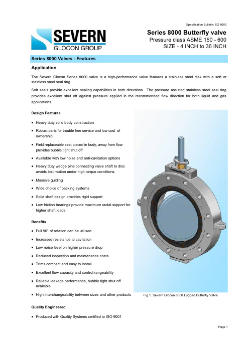
Series 8000 Valves - FeaturesApplicationThe Severn Glocon Series 8000 valve is a high-performance valve features a stainless steel disk with a soft or stainless steel seal ring.Soft seals provide excellent sealing capabilities in both directions. The pressure assisted stainless steel seal ring provides excellent shut off against pressure applied in the recommended flow direction for both liquid and gas applications. Design Featuresx Heavy duty solid body constructionxRobust parts for trouble free service and low cost ofownershipxField replaceable seat placed in body, away from flowprovides bubble tight shut offx Available with low noise and anti-cavitation optionsx Heavy duty wedge pins connecting valve shaft to discavoids lost motion under high torque conditions.x Massive guidingx Wide choice of packing systems x Solid shaft design provides rigid supportx Low friction bearings provide maximum radial support forhigher shaft loads.Benefitsx Full 90° of rotation can be utilised x Increased resistance to cavitation x Low noise level on higher pressure drop x Reduced inspection and maintenance costs x Trims compact and easy to installx Excellent flow capacity and control rangeability x Reliable leakage performance, bubble tight shut offavailablex High interchangeability between sizes and other productsQuality Engineeredx Produced with Quality Systems certified to ISO 9001Specification Bulletin: SG 8000Series 8000 Butterfly valvePressure class ASME 150 - 600SIZE - 4 INCH to 36 INCHFig.1. Severn Glocon 8000 Lugged Butterfly ValvePage 1Fig.2. Series 8000 Butterfly ValveEngineering Data - Severn Glocon Series 8000 ValvesGeneralThe Series 8000 range of valves were developed to provide a cost effective, reliable and easily maintainedcontrol valve capable of working in low pressureenvironments.End connection Sizes3 inch (80 mm) to 36 inch (900 mm).Design Standard API 609Valve Body Ratings ASME 150 - ASME 600 Body Configurations: Wafer, Lug, Double flanged Body Face to Face DimensionsAPI 609 / Severn Glocon standard Standard PackingTeflon/Chevrons and Graphite Plug/Seat Leakage ClassANSI/FCI 70.2. Class IV as standard, Class V with metal seat and Class VI with soft seat insert.Materials of ConstructionA wide range of standard materials are available for both the valve pressure containing parts and trim. These include carbon and stainless steel, duplex/super duplex plus high nickel alloys. Stellite, and other hard facings/coatings areavailable. For full listing on materials consult factory.Paint A wide range of paint finishes are available including enamel, alkyd gloss and various epoxy finishes. Clean BuildSevern Glocon maintains high clean build standards-utilising clean build areas including O xygen clean and aUltra High Purity clean room.Inspection and Testing,QVSHFWLRQ 7HVWLQJ WR 6HYHUQ *ORFRQ¶V VWDQGDUG DV ZHOO DV WR DOPRVW DOO LQWHUQDWLRQDO VWDQGDUGV FXVWRPHU¶V requirements. ActuationVarious types of actuation are available including:- Series P Linear spring pneumatic cylinder,Series N Numotor pneumatic piston,Series W Diaphragm-spring pneumatic actuator.In addition electric, hydraulic, electro hydraulic andmanually operated actuators are available. Instruments A wide range of control instruments are available from Sever Glocon including:-Positioners, Air-filter Regulators, Volume Boosters,Solenoid Valves, and Lock-up Valves. Page 2Valve Body Style OptionThe Severn Glocon Series 8000 valve is available in three basic body styles of either Wafer, Lugged or Flanged. Many parts are interchangeable, with the exception of the valve bodies.Fig.3. Lug type BodyFig.4. Double Flange BodyDisc & Seat ConstructionDouble offset and eccentric disc mounting reducing maintenance costs and downtime. It minimizes the intereference between seat & disc edges allowing longer seat life even under frequent valve operation. The seats are held rigidly by the seat retainer which is inserted within the body per API 609 design requirements.Fig.5. Seat ConfigurationFig.7.Soft Seated typeFig.6.Metal Seated type Metal Seat and Soft SeatVirgin PTFE seat having a flexi lip provides bubble tight shut off in both the directions.Rigid seats like PTFE, Glass filled PTFE, EPDM and Viton,etc. allow a clean flow passage & prevents fluid deposition within the seat. Rigid seats allow unidirectional flow (shaft side inlet) providing tight shutoff under positive & vacuum applications.Flexible Metal seat like Die pressed stainless steel seats with inbuilt flexible property gives Class IV leakage with minimal torque requirements.Page 3H IGH PERFORMANCE BUTTERFLY VALVEPage 4Fig.8. Lug type Butterfly valveFlow coefficients CvThe Cv values by definition are related to the flow of water (Specific gravity =1) in US Gallons per minute with a pressure drop of 1 PSI.Table 1: Cv Factors for 150#Valve size Degrees Openins mm10°20°30°40°50°60°70°80°90°4100 6.8 2763114171248338437451 615016.5 6615427841960782710701103 820030.9 1242895207841135158420022064 1025052.8 21149288613361934263834113517 1230072.6 290677121918382660362846904837 164001325311230222933614865663488459287 205002078281932347852447590103501380014420 24600315126029405292789011550157502100022050 307504911965454882531244518012245633275034388 3690070728306602118841792025938353704574547160Table 2: Cv Factors for 300#Valve size Degrees Openins mm10°20°30°40°50°60°70°80°90°4100 6.2 2558104157228310414435 615014.9 601392503775467449921041 820027.3 1092554596921001136518201911 1025045.6 18342676711561673228230423194 1230063.3 253590106316022319316842174428 164001094351015182727553998543878508243 20500158630147026463990577578751015012100 246002429662254405761188855120751610017006 307504041614376667791022214795201752690028245Table 3: Cv Factors for 600#Valve size Degrees Openins mm10°20°30°40°50°60°70°80°90°4100 5.8 235498147213290375387 615014.7 59137247372538734950979 820026.8 107250451679983134117341788 1025041.2 16538469210441411206026652747 1230058.4 23354598114792140291837743891 1640096385899161924233533481862316424 Note: Apply appropriate piping correction factorPage 5Standard dimensionsFig.9. Lug type Butterfly valvePage 6Fig.10. Double Flange Butterfly valveStandard dimensionsTable 4: Dimensions of Class 150 ValveValve size DIM LUG DIM DIM DIM DIM ins mm A B D E Ø F Ø S3 80 48 86 127 91 70 15.884 100 54 105 146 93 92 15.886 150 59 130 178 97 141 19.058 200 64 153 206 97 185 25.4010 250 71 201 225 104 234 31.7512 300 82 241 270 123 283 38.1016 400 102 306 322 176 370 44.4520 500 127 354 384 194 467 57.1524 600 154 418 438 200 557 63.5030 750 171 577 524 222 711 76.2036 900 213 816 622 207 855 95.25Table 5: Dimensions of Class 300 ValveValve size DIM LUG DIM DIM DIM DIM ins mm A B D E Ø F Ø S3 80 49 77 127 91 70 15.884 100 54 105 146 93 92 15.886 150 59 139 178 97 141 25.408 200 73 185 206 104 179 31.7510 250 83 200 238 123 229 38.1012 300 92 266 280 175 272 44.4516 400 133 415 355 199 348 57.1520 500 160 480 416 222 437 76.2024 600 183 549 492 226 523 88.9030 750 226 774 581 229 692 114.30Table 6: Dimensions of Class 600 ValveValve size DIM LUG DIM DIM DIM DIM ins mm A B D E Ø F Ø S3 80 54 89 127 91 64 15.884 100 64 130 152 97 87 19.056 150 78 172 193 104 132 31.758 200 102 204 232 123 160 38.1010 250 117 336 279 176 202 44.4512 300 140 373 320 191 246 57.1516 400 178 479 407 238 320 76.20Notes:1. For other sizes and rating consult factory2. )RU GLPHQVLRQV ZKHUH XQLW LV QRW LQGLFDWHG FRQVLGHU WKH XQLW DV ³PP´3. Dimensions shown may vary depending upon options selected on actual product4. Also available in Flanged.Page 7Note: DP (Pressure Drop) in PSIThe Torque to open = Unseating Torque + Packing Torque + Frictional Torque Conversion: 1Lbs. Ins = 0.1129 Nm 1Nm=8.85 Lbs. InsCat Ref SG 8000 rev 2009Page 8Manufacturing locations Website: Severn Glocon Ltd.Olympus Park, Quedgeley Gloucester, GL2 4NF, UKTelephone: +44(0) 845 223 2040 Fax: +44 (0) 845 223 2041Severn Unival Ltd.Milford Buildings, Milford StreetHuddersfield W Yorks, HD1 3DY, UK Telephone: +44(0) 148 451 8080 Fax: +44(0) 148 451 8087Severn Glocon India Private Ltd. F-96/97, SIPCOT Industrial Park Irrungattukottai, Chennai ± 602 105Telephone: +91 44 4710 4200Fax: +91 44 4710 0073Valve sizeShaft Size8QVHDWLQJ 7RUTXH >$ % ¨3 @(Lbs Ins) Packing Torque Friction Torque Soft SeatedMetal Seated (Upto 200°C)Fire SafeinsmmAB A B A B (Lbs Ins)(Lbs Ins) 4 1000.75 1840.9 3670.9 230 1.12 740.52 x Dp 615012691.325301.32 337 1.56 99 1.43 x Dp 8 200 1.25 4472.19 893 2.19 559 2.74 1243.37 x Dp 10250 1.256733.319894.878424.12124 5.10 x Dp 12300 1.5 1070 5.05 3213 7.87 1338 6.56 2229.38 x Dp 14350214427432610.5 1803 8.75 29615.45 x Dp 1640021978 9.6 5974 14.5 2472 1229619.06 x Dp 18450 2.2524721274161830901533429.36 x Dp 20500 2.75 2997 14.5 9270 22.5 3747 18.2 40841.20 x Dp 246003453222135963356652244569.01 x Dp 28700 3.5 5923 28.75 17613 42.75 7396 35.93 519106.09 x Dp 30750 3.56798332039449.5849841.25519148.32 x Dp 328003.5 7880 38.25 23690 57.5 9847 47.8519169.95 x DpTable 7: Torque values to Unseat the Valve from Closed Position (150LB Rating)Table 8: Torque values to Unseat the Valve from Closed Position (300LB Rating)The Severn Glocon policy is one of continuous improvement and the right is reserved to modify this specification bulletin without notice.Valve size Shaft Size8QVHDWLQJ 7RUTXH >$ % ¨3 @(Lbs Ins)PackingTorqueFriction TorqueSoft SeatedMetal Seated (Upto 200°C)Fire SafeinsmmABAB A B (Lbs Ins)(Lbs Ins) 4 1000.75 1840.9 3670.9 230 1.12 740.52 x Dp 61500.75 269 1.325301.32 337 1.56 74 1.43 x Dp 8 20014472.19 893 2.19 559 2.74 993.37 x Dp 1025016733.319894.87 8424.1299 5.10 x Dp 12300 1.25 1070 5.05 3213 7.87 1338 6.56 1249.38 x Dp 14350 1.514427432610.518038.7522215.45 x Dp 16400 1.5 1978 9.6 5974 14.5 2472 1222219.06 x Dp 18450 1.75 24721274161830901525929.36 x Dp 2050022997 14.5 9270 22.5 3747 18.2 29641.20 x Dp 24600 2.25453222135963356652233469.01 x Dp 28700 2.5 5923 28.75 17613 42.75 7396 35.93 371106.09 x Dp 3075036798332039449.5 8498 41.25 445148.32 x Dp 3280037880 38.25 2369057.5984747.8445169.95 x Dp。

Butterfly valvesA Butterfly valve is a quarter-turn rotational motion valve, that is used to stop, regulate, and start flow.Butterfly valves are easy and fast to open. A 90° rotation of the handle provides a complete closure or opening of the valve. Large Butterfly valves are usually equipped with a so-called gearbox, where the handwheel by gears is connected to the stem. This simplifies the operation of the valve, but at the expense of speed.Types of Butterfly valvesButterfly valves has a short circular body, a round disc, metal-to-metal or soft seats, top and bottom shaft bearings, and a stuffing box. The construction of aButterfly valve body varies. A commonly used design is the wafer type that fits between two flanges. Another type, the lug wafer design, is held in place between two flanges by bolts that join the two flanges and pass through holes in the valve's outer casing. Butterfly valves are even available with flanged, threaded and butt welding ends, but they are not often applied.Butterfly valves possess many advantages over gate, globe, plug, and ball valves, especially for large valve applications. Savings in weight, space, and cost are the most obvious advantages. The maintenance costs are usually low because there are a minimal number of moving parts and there are no pockets to trap fluids.Butterfly valves are especially well-suited for the handling of large flows of liquids or gases atrelatively low pressures and for the handling of slurries or liquids with large amounts ofsuspended solids.Butterfly valves are built on the principle of a pipe damper. The flow control element is a disk of approximately the same diameter as the inside diameter of the adjoining pipe, which rotates on either a vertical or horizontal axis. When the disk lies parallel to the piping run, the valve is fully opened. When the disk approaches the perpendicular position, the valve is shut. Intermediate positions, for throttling purposes, can be secured in place by handle-locking devices.Butterfly valve Seat ConstructionStoppage of flow is accomplished by the valve disk sealing against a seat that is on the inside diameter periphery of the valve body. Many Butterfly valves have an elastomeric seat against which the disk seals. Other Butterfly valves have a seal ring arrangement that uses a clamp-ring and backing-ring on a serrated edged rubber ring. This design prevents extrusion of the O-rings.In early designs, a metal disk was used to seal against a metal seat. This arrangement did not provide a leak-tight closure, but did provide sufficient closure in some applications (i.e., water distribution lines).Butterfly valve Body ConstructionButterfly valve body construction varies. The most economical is the wafer type that fits between two pipeline flanges. Another type, the lug wafer design, is held in place between two pipe flanges by bolts that join the two flanges and pass through holes in the valve's outer casing. Butterfly valves are available with conventional flanged ends for bolting to pipe flanges, and in a threaded end construction.Seat Disk and Stem of a Butterfly valveThe stem and disk for a Butterfly valve are separate pieces. The disk is bored to receive the stem. Two methods are used to secure the disk to the stem so that the disk rotates as the stem is turned. In the first method, the disk is bored through and secured to the stem with bolts or pins. The alternate method involves boring the disk as before, then shaping the upper stem bore to fit a squared or hex-shaped stem. This method allows the disk to "float" and seek its center in the seat. Uniform sealing is accomplished and external stem fasteners are eliminated. This method of assembly is advantageous in the case of covered disks and in corrosive applications.In order for the disk to be held in the proper position, the stem must extend beyond the bottom of the disk and fit into a bushing in the bottom of the valvebody. One or two similar bushings are along the upper portion of the stem as well. These bushings must be either resistant to the media being handled or sealed so that the corrosive media cannot come into contact with them.Stem seals are accomplished either with packing in a conventional stuffing box or by means of O-ring seals. Some valve manufacturers, particularly those specializing in the handling of corrosive materials, place a stem seal on the inside of the valve so that no material being handled by the valve can come into contact with the valve stem. If a stuffing box or external O-ring is employed, the fluid passing through the valve will come into contact with the valve stem.Typical applications of Butterfly valvesA Butterfly valve can be used in many different fluid services and they perform well in slurry applications. The following are some typical applications of Butterfly valves:∙Cooling water, air, gases, fire protection etc.∙Slurry and similar services∙Vacuum service∙High-pressure and high-temperature water and steam services Advantages of Butterfly valves∙Compact design requires considerably less space, compared to other valves ∙Light in weight∙Quick operation requires less time to open or close∙Available in very large sizes∙Low-pressure drop and high-pressure recovery Disadvantages of Butterfly valves∙Throttling service is limited to low differential pressure∙Cavitation and choked flow are two potential concerns∙Disc movement is unguided and affected by flow turbulence。
Butterfly V alvesContents(1) Be sure to read the following description of ourproduct warranty 1(2) General Operating Instructions2(3) General Instructions for Transportation,Unpacking and Storage3(4) Names of Parts4(5) Comparison between W orking Temperature and Pressure6(6) Installation Procedure7(7) Operating Procedure12(8) Disassembly and Assembly Procedurefor Parts Replacement14(9) Installation Procedure for Handle16(10) Adjustment Procedure forStopper on Gear Type17(11) Inspection Items 18(12) Troubleshooting18(13) Handling of Residual and W aste Materials19User ’s ManualASAHI AV VALVEST ype 57: 40 mm (1 1/2”) - 350 mm (14”) Body: PVC, PP , PVDFT ype 56: 400 mm (16”) Body: PP , PVDFT ype 56D: 400 mm (16”)Body: PDCPDThis User’s Guide contains information important to the proper installation, maintenance and safe use of the ASAHI A V product store in an easily accessible location.WarningCaution-Always observe the specifications of and the precautions and instructions on using our product.-W e always strive to improve product quality and reliability, but cannot guarantee perfection.Therefore, should you intend to use this product with any equipment or machinery that may pose the risk of serious or even fatal injury, or property damage, ensure an appropriate safety design or take other measures with sufficient consideration given to possible problems. W e shall assume no responsibility for any inconvenience stemming from any action on your part without our written consent in the form of specifications or other documented approval.-The related technica l d ocuments,operation manuals,and other documentation prescribe precautions on selecting, constructing, installing, operating, maintaining, and servicing our products. For details, consult with our nearest distributor or agent.-Our product warranty extends for one and a half years after the product is shipped from our factoryor one year after the product is installed, whichever comes first. Any product abnormality that occurs during the warranty period or which is reported to us will be investigated immediately to identify its cause. Should our product be deemed defective, we shall assume the responsibility to repair or replace it free of charge.-Any repair or replacement needed after the warranty period ends shall be charged to the customer.-The warranty does not cover the following cases:(1) Using our product under any condition not covered by our defined scope of warranty.(2) Failure to observe our defined precautions or instructions regarding the construction,installation, handling, maintenance, or servicing of our product.(3) Any inconvenience caused by any product other than ours.(4) Remodeling or otherwise modifying our product by anyone other than us.(5) Using any part of our product for anything other than the intended use of the product.(6) Any abnormality that occurs due to a natural disaster, accident, or other incident not stemming from somethinginside our product.(2) General Operating Instructions- Using a positive-pressure gas with our plastic piping may pose a dangerous condition due to the repellent force particular to compressed gases, even when the gas is under the same pressure as water. Therefore, be sure to take the necessary safety precautions such as covering the piping with protective material. For inquiries, please contact us. For conducting a leak test on newly installed piping, be sure to check for leaks under water pressure. If absolutely necessary to use gas in testing, please consult your nearest service station beforehand.- Do not step on the valve or apply excessive weight on valve. (It can be damaged.)- Keep the valve away from excessive heat or fire. (It can be damaged, or destroyed.)- Operate the valve within the pressure Vs temperature range. (The valve can be damaged by operating beyond the allowable range. - Allow sufficient space for maintenance and inspection.- Select a valve material that is compatible with the media, refer to “CHEMICAL RESIST ANCE ON ASAHI A V V AL VE”.(Some chemicals may damage incompatible valve materials.) - Do not use the valve on condition that fluid has crystallized. (The valve will not operate properly.)- Keep the valve away from places of direct sunlight, water and dust. Use cover to shield the valve. (The valve will not operate properly.) - Perform periodic maintenance.(Leakage may develop due to temperature changes or changes with time during prolonged storage, rest, or operation.)- Gear Operator Operation; we utilize a self-locking worm gear design on our manual operators. This design allows flow control of the valve in intermediate positions in normal process conditions. In applications where very high velocity , turbulence flow or vibration is present and an intermediate setting is required, It is recommended to install a locking device. The locking device will prevent the possibility of the valve drifting in severe condition from it is original intermediate setting.Handle lockWarningCaution(3) General Instructions for Transportation, Unpacking and Storage-In suspending and supporting a valve, take enough care and do not stand under a suspended valve.-The valve is not designed to handle any kind of impact. A void throwing or dropping the valve.-A void scratching the valve with any sharp object.-Do not pile up corrugated cardboard packages one on top of another too much. Excessively piled-uppackages may collapse.-A void contact with any coal tar creosote, insecticides, vermicides or paint.(The force of swelling may damage the valve.)-When transporting a valve, do not carry it by the handle.-Store valves in the original corrugated cardboard boxes, avoid direct sunlight, and store it indoors (atRoom Temperature). Also avoid storing it in a place which may become very hot.(Corrugated cardboard packages become weaker as they become wet with water or other liquid.Take enough care in storage and handling.)-After unpacking the products, check that they are defect-free and meet the specifications.WarningCautionType56 (Gear Type): 400mm (16”)Body material: PP, PVDF, PDCPD** Reference figure(5) Comparison between working temperature and pressure[70][150]W o r k i n g p r e s s u r e (M P a ) [P S I ][70][150]W o r k i n g p r e s s u r e (M P a ) [P S I ][70][150]W o r k i n g p r e s s u r e (M P a ) [P S I ]BUTTERFLY VALVE TYPE57[70][150]W o r k i n g p r e s s u r e (M P a ) [P S I ][70][150]W o r k i n g p r e s s u r e (M P a ) [P S I ]BUTTERFLY VALVE TYPE57(6) Installation Procedure- In suspending and supporting a valve, take enough care and do not stand under a suspended valve.- Be sure to conduct a safety check on the machine tools and motor-driven tools to be used, beforebeginning work. - W ear protective gloves and safety goggles as fluid remains in the valve. (Y ou may be injured.)-When installing a pipe support by means of a U-band or something similar, take care not to overtighten. (Excessive tension may damage it.)- When installing pipes and valves, ensure that they are not subjected to tension, compression, bending, impact, or other excessive stress. - Use flat faced flanges for connection to A V V alves.- Ensure that the mating flanges are of the same standards.- When installing the piping, do not do so with the valves fully closed.(The disc may pinch into the seat, resulting in a high operating torque, thus disabling opening and closing.) - The gasket is unnecessary.(The seat carries out the role of the gasket.)WarningCautionCautionCautionProcedure -The parallelism and axial misalignment of the flange surface should be under the values shown in the following table The parallelism and axial misalignment of the flange surface should be under the values shown in theA failure to observe them can cause destruction due to stress application to the pipe )3) Tighten the bolts and nuts gradually with torque wrench to the specified torque in a diagonal manner. (Fig. 6-3)- Tighten the bolts and nuts gradually with a torque wrench to thespecified torque level in a diagonal manner.Fig. 6-3The disk [2] is prevented from overflowing. (The disk [2] is damaged.)CautionCautionCautionCaution : A void excessive tightening. (The valve can be damaged.)<ANSI Standard>Body Material: PVC, PP, PVDF<ANSI Standard>Body Material: PDCPDNote:Longer bolts may be required for stub-end and back-up ring arrangements. Always double check your mating flange thickness before assuming any bolt lengths.(7) Operating Procedure-Do not use the valve to fluid containing slurry.(The valve will not operate properly.)-The installed valve must never be opened or closed when foreign matter such as sand is present in thepipeline.-Do not exert excessive force in closing the valve.-When operating the handle, be sure to do so with your hand. (Using a tool may damage the handle.)1)Open and close the valve by turning handle smoothly.(Turn clockwise to close and counterclockwise to open.)2)In case of lever type (40-200 mm{1 1/2”-8”}), the direction of handle is same a s the disc as shown in Fig. 6-1.-The adjustments for full-opened and full-shut position are set using the stopper adjuster.Fig. 7 – 2CautionCautionTechnical Data for OperationNote : Data mentioned in the table above is reference only.These data are measured in standard condition and it slightly differs depending on conditions.(8) Disassembly and Assembly Procedure for Parts Replacement- The handle part can be removed with line pressure present. The stem retainer can't be removed with linepressure present. If stem retainer needs to be removed, there can not be line pressure present.- W ear protective gloves and safety goggles as fluid remains in the valve.(Y ou may be injured.)- When installing pipes and valves, ensure that they are not subjected to tension, compression, bending,impact, or other excessive stress.- Do not change or replace valve parts under line pressure.Gear Type <Nominal size 40mm-400mm (1 1/2”-16”)5) Loosen set bolt [28] for gear box [25] and pull off the gear box upward with gasket [158]*. (*Nominal Size: 400mm is gasket [25])6) <Nominal size 40mm-350mm (1 1/2”-14”) *It advances 400mm (16”) as follows.>To take off stem holder [8]. Release 4 tapping screws [157] by using screw driver (+).WarningCautionLever & Gear Type7)Hold flat surface of Stem [7] with vise and pull off valve body[1].8)(A) Set the valve body [1] on square lumbers at edges of valve body on the press and put a lumber on the disc[2].Operate the press slowly and push disc [2] and seat [3] out if the valve body[1].(B) Set the valve body [1] on square lumbers at edges of valve body and put a circular stick on the disc[2].Strike the circular stick with a hammer and remove disc [2] and seat [3] out of the valve body[1].9)Set the disc [2] parallel to the working desk to half opened position. Push the seat[3], and remove the disc[2].10)<Nominal size 40mm-350mm (1 1/2”-14”) *It advances 400mm (16”) as follows.>Remove the stabilization ring [156] and the O-ring(C) [6]from the stem[7].<< Assembly >>Procedure1)Put the O-ring(C) [6]onto the stem[7].2)Before starting assembly, grease (Silicone) should be spread on the top and bottom disc[2], the stem hole of theseat [3] and the stem O-ring(C)[6].3)<Nominal size: 40mm-350mm(1 1/2”-14”) *It advances 400mm (16”) as follows.>Insert the stabilization ring [156] into the upper side slot of the seat [3]. The upper side slot of seat [3] has largerstem hole than lower side.Make certain tabs are properly aligned. Both upper and lower stabilization ring [156] are identical.4)Insert the stem [7] about 1/3 into the body [1]. Install the seat [3] into the body [1] by aligning upper seat stem holewith the stem [7].5)Collapse the left or right side of seat [3] in towards opposing side exposing lower stem hole by screw driver (–).<Nominal size: 40mm-350mm (1 1/2”-14”) *It advances 400mm (16”) as follows.>Install the stabilization ring [156]into the body [1] aligning tabs of ring with center groove of the body [1]. Seat[3]tabs should line up when bottom of seat is reset into body of valve.6)Remove the stem [7].7)Reset the seat [3] into the body [1].<Nominal size: 40mm-350mm(1 1/28)To install disc [2], make certain valve size on disc [2] is in upright direction. Install top of disc [2] into seat [3]aligningwith upper stem hole.9)Rotate disc [2] to 75% (Approx.) closed position and install stem [7] about 50% into the body [1].10)Press in bottom of disc [2] to lower stem hole.Look into valve body [1] to be certain full square in disc [2] is centered with upper valve [1] stem hole. If not, repeat 11) Install the stem [7] into valve body [1] and disc [2]. If disc [2] is properly aligned, stem [7] should slide in smoothly .If stem [7] does not slide in smoothly , report from step 8) to properly align the disc [2] in the valve body [1]. 12) <Nominal size: 40mm-350mm(1 1/2”-14”) *It advances 400mm (16”) as follows.>Install stem holder [8] onto valve body [1] with countersunk holes facing up using 4 screws [157]. 13) To install lever or gear operator reverse disassembly procedure #5).14) After assembly , make sure that the valve can be fully opened and closed smoothly.(9) Installation procedure for handle《Installation 》Procedure1) with the indication line at the top o f stem. 2) Secure the handle at the top of stem with the attached bolts washer, using socket wrench.3)handle, and install the cap by striking lightly by using a hammer.Do not use excessive force in installing or removing the cap. Caution《Remove 》 Procedure1)(–). 2) handle.- Do not use excessive force, in installing or removing the cap.(It can be damaged )(10) Adjustment Procedure for Stopper Gear TypeThe adjustments for full-opened and full-shut position are set using the stopper adjuster. Adjustment for Full-shut (Full-opened) position1) Remove the rubber cap of Full-closing (Full-opening)adjuster.2) Loosen the first stopper hex-bolt completely by allen wrench.3) Adjust the disc of valve to required position. 4) Tighten the stopper hex-bolts until it just stops.5) Put the rubber cap of Full-closing (Full-opening) adjuster back on gearbox by hand.Adjuster for Full-Shut PositionAdjuster for Full-Opened PositionRubber CapCaution(11) Inspection Items- Perform periodic maintenance.(Leakage may develop due to temperature changes or changes with time during prolonged storage, rest, or operation.)Inspect the following items.(12) TroubleshootingCaution(13) Handling of Residual and Waste Materials- Make sure to consult a waste treatment dealer to dispose of the valves.(Poisonous gas is generated when the valve is burned improperly.)Butterfly V alves40mm-350mm(1 1/2”-16”) Type 57400mm(18”) : Type 56Information in this manual is subject to change without notice.2009.8ASAHI AV VALVESCaution。
文件号: NWD 0406版本号: 2006BS系列电动固定球阀使用说明书受控本非受控本编制日期 .审核日期 .批准日期 .苏州纽威阀门有限公司NEWAY VALVE(SUZHOU)CO., LTD地址:中国江苏省苏州新区湘江路999号,215129电话:0086-512-6665 1365传真:0086-512-6665 1360E-mail:***************.cnWEB: 文件修改记录版本号修改页/节修改说明实施日期更改单号2006 新版 2006-3-17目录1.前言 (3)2. 欧共体关于承压设备和防爆指令对健康和安全的基本要求 (3)3. 用途和技术性能 (4)4. 阀门结构 (5)5. 运输和保管 (8)6. 安装 (8)7. 移动 (9)8. 拆卸程序 (9)9. 重装程序 (10)10.阀门操作和维护 (12)11.电动执行器的使用说明 (14)12.故障及维修 (16)13.质量保证及服务 (17)1.前言1.1 感谢您选择纽威阀门。
作为一种承压设备,当阀门用于输送流体及易燃易爆气体时,由于泄露或使用不当往往存在一些安全隐患,从安全角度考虑,用户使用前,应仔细阅读本说明书,了解纽威在设计和制造过程中所采取的安全措施,以防患于未然。
2. 欧共体关于承压设备和防爆指令对健康和安全的基本要求2.1 纽威的设计理念—球阀作为一种标准产品来设计,由于它的范围较广所以并不考虑每一个细节的工作条件。
—球阀设计参照API 6D,阀门强度参照ASME B16.34 压力—温度额定值。
—阀门密封材料应根据介质对材料的抗腐蚀性和耐磨损的要求而选择,参照API 6D。
—阀门设计时应有防静电装置及防火结构,放火实验设备符合API 607及API 6FA 规范,并已通过英国的劳氏船级社认证。
—阀门不含轻金属(例如镁),各零部件通过相互接触形成导电通路,通过管道流向大地,以防止静电积累。
—阀门根据它的型号、扭矩、及操作要求等,配置合适的电动驱动装置。