Project02_PointDefects分子动力学实验:点缺陷
- 格式:pdf
- 大小:1.23 MB
- 文档页数:12


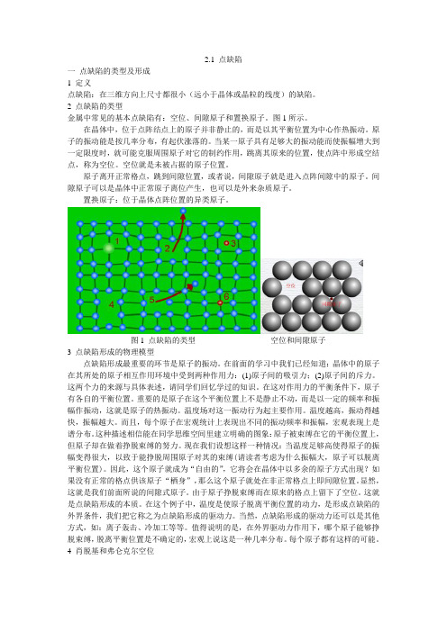
2.1 点缺陷一点缺陷的类型及形成1 定义点缺陷:在三维方向上尺寸都很小(远小于晶体或晶粒的线度)的缺陷。
2 点缺陷的类型金属中常见的基本点缺陷有:空位、间隙原子和置换原子。
图1所示。
在晶体中,位于点阵结点上的原子并非静止的,而是以其平衡位置为中心作热振动。
原子的振动能是按几率分布,有起伏涨落的。
当某一原子具有足够大的振动能而使振幅增大到一定限度时,就可能克服周围原子对它的制约作用,跳离其原来的位置,使点阵中形成空结点,称为空位。
空位就是未被占据的原子位置。
原子离开正常格点,跳到间隙位置,或者说,间隙原子就是进入点阵间隙中的原子。
间隙原子可以是晶体中正常原子离位产生,也可以是外来杂质原子。
置换原子:位于晶体点阵位置的异类原子。
图1 点缺陷的类型空位和间隙原子3 点缺陷形成的物理模型点缺陷形成最重要的环节是原子的振动。
在前面的学习中我们已经知道:晶体中的原子在其所处的原子相互作用环境中受到两种作用力:(1)原子间的吸引力;(2)原子间的斥力。
这两个力的来源与具体表述,请同学们回忆学过的知识。
在这对作用力的平衡条件下,原子有各自的平衡位置。
重要的是原子在这个平衡位置上不是静止不动,而是以一定的频率和振幅作振动,这就是原子的热振动。
温度场对这一振动行为起主要作用。
温度越高,振动得越快,振幅越大。
而且,每个原子在宏观统计上表现出不同的振动频率和振幅,宏观表现上是谱分布。
这种描述相信能在同学思维空间里建立明确的图象:原子被束缚在它的平衡位置上,但原子却在做着挣脱束缚的努力。
现在我们设想这样一种情况:当温度足够高使得原子的振幅变得很大,以致于能挣脱周围原子对其的束缚(请读者考虑为什么振幅大,原子可以脱离平衡位置)。
因此,这个原子就成为“自由的”,它将会在晶体中以多余的原子方式出现?如果没有正常的格点供该原子“栖身”,那么这个原子就处在非正常格点上即间隙位置。
显然,这就是我们前面所说的间隙式原子。
由于原子挣脱束缚而在原来的格点上留下了空位。
第25卷 第2期Vol 125 No 12材 料 科 学 与 工 程 学 报Journal of Materials Science &Engineering总第106期Apr.2007文章编号:167322812(2007)022*******硅晶体中点缺陷结合过程的分子动力学模拟王慧娟,陈 成,邓联文,江建军(华中科技大学电子科学与技术系,湖北武汉 430074) 【摘 要】 本文采用分子动力学方法模拟了硅晶体中空位与间隙原子的结合过程。
利用S tillinger 2Waber 三体经验势函数表征原子间的相互作用,采用Verlet 积分算法,在VC ++环境下使用C ++语言编程,进行计算机模拟。
结果表明,空位和间隙原子倾向于通过<111>方向结合,并且在运动过程中存在着势垒,势垒值为0.5~1.2eV 。
【关键词】 分子动力学模拟;点缺陷;扩散中图分类号:O77 文献标识码:AMolecular Dynamics Simulation on V acancy 2interstitial Annihilationin SiliconWANG H ui 2juan ,CHEN Cheng ,DENG Lian 2w en ,JIANG Jian 2jun(Dep artment of electronic science &technology ,H u azhong U niversity of Science &T echnology ,Wuh an 430074,China)【Abstract 】 M olecular dynamics simulation is performed to study the vacancy 2interstitial annihilation in crystalline silicon.We choose the S tillinger 2Weber (SW )potential ,which is comm only used for silicon ,to describe the interaction between atoms.The simulation is calculated by Verlet alg orithm and programmed through C ++in the environment of VC ++.The result shows that <111>is the preferred combination direction and there exists an energy barrier in the m otion ,the value of which is between 0.5eV and 1.2eV.【K ey w ords 】 m olecular dynamic simulation ;vacancy and interstitial ;diffusion收稿日期:2006206210;修订日期:2006208218作者简介:王慧娟(1984-),女,湖南邵阳人,硕士研究生,主要从事半导体材料与器件研究。
MD Project # 2Point Defects in Metals:Vacancies and Interstitials1.VacancyA vacancy is created when an atom within a lattice is removed. Here we discuss how to introduce a vacancy using LAMMPS and how to compute the vacancy formation energy, E v.LAMMPS input file, in.vacancy1) Creates a vacancy in a perfect crystal (FCC Copper)LAMMPS creates a perfect crystal of 4 ×N×N×N Cu atoms with edges along <100> directions. Then an atom is removed. (N is the size of the simulation box)2) RelaxationWhen an atom is removed from a crystal, the surrounding atoms will readjust their atomic positions to lower the potential energy. To obtain such a relaxed vacancy configuration one may use energy minimization techniques. In the sample, the conjugate gradient (CG) or an alternative algorithm (sd) may be used to minimize the energy.The input file in.vacancy:3) Run Lammps4) Calculate the Vacancy Formation EnergyThe vacancy concentration at thermal equilibrium is given by[n ] = exp( − F v / k B T )where F v = E v − TS v is the Helmholtz free energy to form a vacancy. Neglect the entropy contribution S v (~ 2k B for Cu), we have[n ] ~ exp( −E v / k B T )The equation also apply for other point defects such as interstitials (see later).Let E 1 be the energy of the perfect crystal with N atoms, and E 2 the relaxed energy of the system containing the vacancy (N – 1 atoms). The vacancy formation energy E v can be computed from211v N E E E N −≡−or ()21v coh E E N E ≡−−where E coh = E 1 / N , the cohesive energy of the perfect crystal. The result for FCC Cu using the EAM potential with a supercell of 4×(20×20×20) atoms is E v ~1.26 eV, comparing to ~1.28 eV provided in literature.The [n] can then be estimated to be ~ 7.59×10⁻²² and ~ 2.2×10⁻⁵ at T=300 K and 1350 K (T m ), respectively (Note: 1 eV/k B = 1.1604×10⁻⁴ K; [n]~2×10⁻⁴ for Cu in literature)Fig. 1 The vacant site locates in the center of a FCC 4×(6×6×6) crystal of Cu, with 106c a =,206c a = and 306c a =. Colored according to potential energy per atom.2. InterstitialAn interstitial is created when an atom is inserted into a perfect lattice. If the additional atom is of the same type as lattice atoms, it is called a self-interstitial.Similar to vacancy, we use LAMMPS to calculate the formation energy (E i ) of aself-interstitial in Cu.211i N E E E N+≡− E i (relaxed) might depend on the site the atom was initially introduced, but there should be an optimized interstitialcy associated with a minimum E i .In several FCC metals such as Cu, Ni and Pt, the most stable self-interstitial configuration is a split structure, with two atoms displaced in positive and negative [100] directions, the so-called “dumbbell” interstitialcy (Fig. 2).Fig. 2 A Dumb-bell interstitial configuration. Right, that for Cu obtained using LAMMPS.When an interstitial is introduced, the surrounding atoms will readjust their positions to lower the potential energy. To obtain the relaxed configuration one may use the energy minimization technique. In our sample, the ‘sd’-algorithm will be used for such a purpose.To find a configuration with the minimum energy, we choose to use an energy minimization combined with a thermal equilibrations (via a NVT or NVE ensemble). Temperature effects are included in order to help atoms to find the most stable interstitial configuration. Then we “quench” it to 0 K via energy minimization and calculate the energy.The input file in.interstitial looks likeFor a system of 32000 atoms, we found the interstitial energy E i ~ 3.1 eV for Cu.Similarly, the [n i] for Cu can then be estimated to be ~ 8.4×10-53 and ~ 2.7×10⁻¹² at T=300 K and 1350 K (T m), respectively.DiscussionsVarious interstitial configurations may be observed if atoms are not relaxed enough, see Figs.3 and 4.1.Check how Ev depends on the system size.2.Calculate possible interstitial formation energies for Cu, map out the most stableinterstitial configuration for Cu.(a)(b) (c)Fig. 3 Octahedral (red) and tetrahedral (blue) interstitial symmetry polyhedra in a FCC lattice (a). The most stable interstitial site is supposed to be the center of the octahedron instead of the tetrahedron, as revealed in (b) and (c).Fig. 4 Possible configurations of interstitials。