Dup(1)PXR7富士温控表说明书
- 格式:xls
- 大小:37.50 KB
- 文档页数:12
− 1 −− 2 −注) 上段(PV)显示消失(无显示)时,请在参数DP13的设定值上加64。
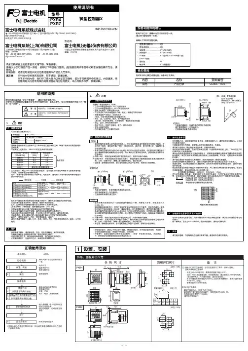
2接线3使用方法(请在使用前阅读)6关于温度调节器的功能− 3 −− 4 −7为熟练使用温度调节器Modbus RTU 是modicon 公司的商标。
8请在显示异常时阅读* DC4-20mA 输入时,除使用250Ω的外置电阻外,还请作为DC1-5V 输入使用。
注1) 仅同一类型中可以变更代码。
注1) 输入精度为±0.5%FS±1digit±1°C 。
但,采用热敏电阻时,则为±1%FS±1digit 。
R 热电偶0~500°CB 热电偶0~400°C注2) 采用测温电阻时,即使低于-150°C ,也不显示LLLL 。
注3)设定低于上表的最小量程时,不能保证输入精度。
的范围内,有时由于传感器的特性,不能正确显示。
*1 微型控制器X 系列与其他机型的不同点如下表所示,请加以注意。
*2 连接计算机时,需要通信变换器。
另行准备(推荐产品) (株)RA 系统公司生产 RC-77(隔离型) http://www.ras.co.jp (株)lineeye 公司生产 SI-30A(隔离型) http://www.lineeye.co.jp (株)系统sacom 公司生产 KS485(非隔离型) http://www.sacom.co.jp 规 格电源电压:AC100(-15%)~240V(+10%)、50/60Hz 、DC/AC 24V(±10%)功耗:10VA 以下(AC100V),12VA 以下(AC220V),12VA 以下(AC/DC24V)继电器接点输出:控制输出1 1c 接点AC220V/DC30V ,3A(阻性负载)控制输出2 1a 接点AC220V/DC30V ,3A(阻性负载)SSR/SSC 驱动输出*1(电压脉冲输出):ON 时 DC24V(DC17~25V)OFF 时 DC0.5V 以下最大电流 DC20mA 以下负载电阻 850Ω以上DC4-20mA 输出:容许负载电阻 600Ω以下报警输出(最多2点):继电器接点(1a 接点) AC220V/DC30V 1A(阻性负载)加热器断线报警输出:继电器接点(1a 接点) AC220V/DC30V 1A(阻性负载)通信功能*2:RS-485接口传输方式/半双工位串行起止同步传输速度/9600bps通信协议/符合Modbus RTU 或Z-ASCII (PXR 协议)传输距离/最大500m(连接总长度)连接台数/31台数字量输入:输入点数2点 (ON 判定:DC3V 以上,OFF 判定:DC2V 以下)输入接点容量 DC5V / 2mA 输入脉冲宽度 最小0.5秒传送输出:输出精度 ±0.3%以下容许负载电阻 600Ω以下远程SV 输入:输入精度 ±0.5%FS 以下(无输入断线检测功能)设定分辨率 3000以上带输入滤波功能使用及贮存温度:-10°C ~50°C ,90%RH 以下(无结露)-10°C ~45°C(密集安装时)-20°C ~60°C(贮存温度)时间精度:±0.5%以内SSR/SSC 驱动输出DC4-20mA 输出容许负载电阻电压最大电流PXR3DC15V 20mA 100~500ΩPXR4/5/7/9DC24V 20mA 600Ω以下PXV3DC5.5V 20mA 600Ω以下PXV/W/Z DC24V 60mA 600Ω以下[所谓过量程方向]输入在范围之外或异常时的输出方向。

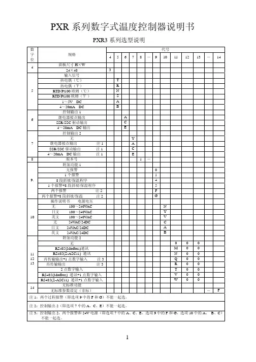
PXR 系列数字式温度控制器说明书PXR3系列选型说明 代号 数字位规格 45678-9101112 13 - 14面板尺寸H ×W 4 24×48 3 输入信号 热电偶(℃) T 热电偶(℉) R RTD/Pt100欧姆(℃) N RTD/Pt100欧姆(℉。
) S 1~5V DC A 54~20mA DC B 控制输出1 继电器接点输出 A SSR/SSC 驱动输出 C 64~20mA DC 输出 E 控制输出2 无 Y 继电器接点输出 注1 A SSR/SSC 驱动输出 注1 C 74~20mA DC 输出 注1 E 8版本号 1- 附加功能1 无报警 0 1个报警 1 8段斜坡/保温程序 4 1个报警+8段斜坡/保温程序 5 两个报警 注2 F 9.两个报警+8段斜坡/保温 注2 G 操作说明书 电源电压 无 100~240V AC N 日文 100~240V AC Y 英文 100~240V AC V 无 24V AC/24DC C 日文 24V AC/24DC A 10英文 24V AC/24DC B 附加功能2 无 0 0 0 RS485(Modbus)通讯 M 0 0 RS485(Z-ASC11) 通讯 N 0 0 再传输输出+1点数字输入 注3 Q 0 0 再传输输出 注3 R 0 0 2点数字输入 T 0 0 RS485(Modbus) 通讯+1点数字输入 V 0 0 111213RS485(Z-ASC11) 通讯+1点数字输入 W 0 0 无标准功能14 无标准参数设定(非标) - F 注1:两个过程报警(即选项9中的F 和G )不能一起选。
注2:控制输出2(即选项7中的A 、C 、E )不能一起选。
注3:控制输出2,两个报警和24V 电源(即选项7中的A 、C 、E 、选项9中的F 和G ,选项10中的A 、 B 、C )不能一起选。
PXR4系列选型说明 代号 数字位规格 45678-910 11 12 13面板尺寸W ×H 4 48×48mm 4 输入信号 热电偶(℃) T 热电偶(℉) R RTD/Pt100欧姆(℃) N RTD/Pt100欧姆(℉。

富士PXR系列温度控制器参数设定
一、设置参数:
1.按SEL约1秒进入第一组参数表;
2.按SEL约3秒进入第二组参数表;
3.按SEL约5秒进入第三组参数表;
4.以上如持续按SEL不放,将回到原始状态;
5.进入参数模式时,如超过30秒无设定动作,显示将回到原始状态。
二、无法设定参数时,检查LOC是否锁定
锁定按键(LOC范围:0,1,2,3,4,5)
*按键锁LOC
*本功能可将控制器内部参数依不同使用程度设定。
0:所有参数均可盘面/通讯设定;
1:所有参数盘面均不可设定,只能通讯设定;
2:仅能盘面键入设定值,所有参数均可通讯设定;
3:所有参数均可盘面设定,无法通讯设定;
4:所有参数均可盘面通讯设定;
5:仅能设定设定值,所有参数均无法设定。
PXR 系列数字式温度控制器说明书PXR3系列选型说明 代号 数字位规格 45678-9101112 13 - 14面板尺寸H ×W 4 24×48 3 输入信号 热电偶(℃) T 热电偶(℉) R RTD/Pt100欧姆(℃) N RTD/Pt100欧姆(℉。
) S 1~5V DC A 54~20mA DC B 控制输出1 继电器接点输出 A SSR/SSC 驱动输出 C 64~20mA DC 输出 E 控制输出2 无 Y 继电器接点输出 注1 A SSR/SSC 驱动输出 注1 C 74~20mA DC 输出 注1 E 8版本号 1- 附加功能1 无报警 0 1个报警 1 8段斜坡/保温程序 4 1个报警+8段斜坡/保温程序 5 两个报警 注2 F 9.两个报警+8段斜坡/保温 注2 G 操作说明书 电源电压 无 100~240V AC N 日文 100~240V AC Y 英文 100~240V AC V 无 24V AC/24DC C 日文 24V AC/24DC A 10英文 24V AC/24DC B 附加功能2 无 0 0 0 RS485(Modbus)通讯 M 0 0 RS485(Z-ASC11) 通讯 N 0 0 再传输输出+1点数字输入 注3 Q 0 0 再传输输出 注3 R 0 0 2点数字输入 T 0 0 RS485(Modbus) 通讯+1点数字输入 V 0 0 111213RS485(Z-ASC11) 通讯+1点数字输入 W 0 0 无标准功能14 无标准参数设定(非标) - F 注1:两个过程报警(即选项9中的F 和G )不能一起选。
注2:控制输出2(即选项7中的A 、C 、E )不能一起选。
注3:控制输出2,两个报警和24V 电源(即选项7中的A 、C 、E 、选项9中的F 和G ,选项10中的A 、 B 、C )不能一起选。
PXR4系列选型说明 代号 数字位规格 45678-910 11 12 13面板尺寸W ×H 4 48×48mm 4 输入信号 热电偶(℃) T 热电偶(℉) R RTD/Pt100欧姆(℃) N RTD/Pt100欧姆(℉。
富士PXW9温度控制仪操作指南名称功能输出1指示灯灯亮为输出1为ON输出2指示灯灯亮为输出2为ONPV(测量值) 指示测量值报警灯检测出报警时灯亮,报警输出为ONSV(设定值) 指示设定值,在设定参数时,指示参数数据SEL键参数选择键选择SV/PV显示,选择参数,选择参数和参数值显示等增/减键改变SV值,顺序选择参数。
在参数设定时,增/减参数数值SV指示灯显示设定值(SV)时,此灯亮注意:当无操作状态持续30秒时,将返回接通电源时的状态,新设定的数据可能没储存。
因此应按SEL键返回初始状态。
一. 基本操作:1.1控制温度SV的设置:按∧键提高设定温度,按∨键降低设定温度(在锁定状态下不能修改)。
1.2第一组参数设定:在PV/SV显示模式下按 SEL键3秒后进入第一组参数设定模式,每按一次SEL键参数将依次显示。
按∧键或∨键可改变设定参数的值。
1.3第二组参数设定在PV/SV显示模式下按SEL键7秒进入第二组参数设定模式,按∧键或∨键可改变设定参数的项目,选定要修改的项目后按SEL键进入参数设定窗口,按∧键或∨键设定参数值,设定完成后按SEL键回到参数项目设置模式,再按∧键或∨键可选择其它参数继续设置。
1.4第三组参数设定在PV/SV显示模式下按SEL键9秒进入第三组参数设定模式,按∧键或∨键可改变设定参数的项目,选定要修改的项目后按SEL键进入参数设定窗口,按∧键或∨键设定参数值。
设定完成后按SEL键回到参数项目设置模式,再按∧键或∨键可选择其它参数继续设置。
二.有关参数的选择:2.1输入信号种类设定(P-n2) 输入信号 输人量程()℃代码(P-n2)输入信号输人量程()℃代码(P-n2)Ptl00 0~150 1 J 0~400 2 Ptl00 0~300 1 J 0~800 2 Ptl00 0~500 1K 0~400 3 Ptl00 0~600 1 K 0~800 3 Ptl00 -50~100 1 K 0~1200 3 Ptl00 -100~200 1 R 0~1600 4 Ptl00-150~600 1B 0~1800 5 热 电 阻Ptl00 -150~850 1S 0~1600 6 T -199~200 7 T-150~4007D C电压DC1~5V16E 0~800 8 E -199~800 8N 0~1300 12 D C 电流 DC4~20mA 刻度范围: -1999~9999对电流输入,应并接250Ω电阻。
温湿度控制器一、产品概述温湿度控制器,主要应用于需要对被测环境进行自动温湿度调节的场合,用户可通过按键分别调整温湿度的上、下限值来控制加热或排风实现自动控制,显示方式为数码管显示。
二、基本功能:2.1 温度测量范围:-25℃~+80℃±1℃;2.2 湿度测量范围:相对湿度RH: 0%~99% 精度±3%RH;2.3 控制方式:温度采用上、下限和回差控制,湿度采用上、下限控制,所有参数均可设置;2.4 输出控制类型:两组继电器触点,分别为加热和排风,每路最大负载AC250V /3A,均为有源输出。
三、技术指标:3.1电源:AC 220V±20%3.2 工作环境:温度:-25℃~+55℃,相对湿度:<95%RH3.3控制设定范围:温度:0℃~80℃,相对湿度:50%RH~99%RH3.4 本机功耗:<3W3.5自检功能:若数码管显示“–––”,则为检测到传感器故障;若加热或排风运行过程中相应指示灯熄灭,则检测到加热或排风故障。
四、工作原理:4.1 温度控制:当被测环境温度低于设定温度下限时,本仪器启动电加热设备开始加温,此时加热指示灯亮,温度升至比下限温度设定值高回差值时,即:W测≥W下限+回差,停止加温。
当被测环境温度高于设定温度上限时,本仪器启动降温设备(如风机或空调)开始降温,此时排风指示灯亮,温度降至比上限温度设定值低回差值时,即:W测≤W上限-回差,停止降温。
4.2 湿度控制:当被测环境湿度超过设定湿度上限时。
如果当前温度较高,即:W测≥W下限+(W上限-W下限)×3÷4,采用降温(或排风,视具体地区采用不同设备)抽湿,此时排风指示灯亮;抽湿过程中,如果温度低于下限温度+2度后,自动转为加热降湿;当降湿过程中温度高于上限温度-2度后,自动转为降温抽湿,直至湿度低于设定下限值为止。
当被测环境湿度超过设定湿度上限时。
如果当前温度较低,即:W测<W下限+(W上限-W下限)×3÷4,采用加热降湿,此时加热指示灯亮,降湿过程中,如果温度高于上限温度-2度后,自动转为降温抽湿;当温度低于下限温度+2度后,自动转为加热降湿,直至湿度低于设定下限值为止。
Micro-controller XModel: PXR4/5/9Operation ManualECNO:406cTable of Contents1.Part Names and Functions (6)2.Operations (7)2-1 Parameter list (7)2-2 Basic operations (12)2-3 Parameter functions and method of settings (13)Standby setting (14)Local/remote operation setting (15)Ramp-soak control (16)Canceling the alarm latch (17)Auto-tuning function (18)Displaying ON-delay alarm or the remaining time of timers (19)Setting alarm 1, 2 and 3 (20)Upper limit of alarm 1, 2 and 3 (20)Lower limit of alarm 1, 2 and 3 (20)Key lock (21)Proportional band (22)Integral time (23)Derivative time (24)Hysteresis range for ON/OFF control (25)Cooling-side proportional band coefficient (26)Cooling-side proportional band shift (Dead band/Overlap band) (27)Output offset value (28)Anti-reset windup (28)Control algorithm (29)PV (Measured value) stable range (33)HYS (Hysteresis) mode at ON/OFF control (34)Cycle time of control output 1 (35)Cycle time of control output 2 (Cooling-side) (36)Input signal code (37)Setting the measuring range (Input range) (38)Selection °C / °F (38)Decimal point position (40)PV (Measured value) offset (41)SV (Setting value) offset (42)Time constant of input filter (43)Alarm types (44)Selecting ramp-soak patterns (47)Ramp-soak status display (48)1st to 8th target SV (48)1st to 8th ramp segment time (48)1st to 8th soak segment time (48)Ramp-soak modes (48)2Specifying control action and output direction at input burn-out (51)SV (Setting value) lower limiter (52)SV (Setting value) upper limiter (52)The time of ON-delay alarm or timer function (53)Displaying current detector input (55)HB (Set value of heater break alarm) (55)Hysteresis alarm 1, 2 and 3 (57)Options of alarm 1, 2 and 3 (58)Upper and lower limits for control output 1 (60)Upper and lower limits for control output 2 (60)Output limit types (61)Output value display (62)RCJ (Cold junction compensation) (63)Adjusting the PV (Measured value) display (0%) (64)Adjusting the PV (Measured value) display (100%) (64)DI1/2 (Digital input 1/2) operation (65)Station No. for communication (68)Parity for communication (69)Communication protocol setting (70)Re-transmission output type setting (71)Re-transmission base and span scale (72)Remote SV input (0%) adjustment (73)Remote SV input (100%) adjustment (73)Remote SV input filter constant (74)Remote SV input value display (75)Parameter display mask (76)3.Troubleshooting (77)Index (79)3PXR4Note 1: Cannot be combined with heater break alarm.( 2, 3, 6, 7, H cannot be specified on 9th digit.)Note 2: Cannot be combined with alarm (1 pc.) + heater break alarm, alarm (2 pcs.), or alarm (3pcs.).( 3, 7, F, G, H, M, P cannot be specified on 9th digit.)Note 3: Cannot be combined with RS485 + 1-point digital input.(V and W cannot be specified on 11th digit.)Note 4: In the case of control output 2, either of heater break alarm or remote SV input can be selected.(A, C, E and R on the 7th digit, and 2,3,6,7,H, D and P on the 9th digit cannot be specified.)Input signal, measurement range, and set value at the time of deliver are as follows.When thermocouple is specified: Thermocouple K, Measurement range; 0 to 400°C, Set value; 0°CWhen resistance bulb is specified: Pt, Measurement range; 0 to 150°C, Set value; 0°CWhen voltage/current is specified: Scaling; 0 to 100%, Set value; 0%For the cases other than the above, specify input signal and measurement range.Input signal of the thermocouple and the resistance bulb can be switched by key operation on the front panel.The actuating method of the control output has been set to reverse for control output 1, and to direct for controloutput 2 at the time of delivery. Note that reverse and direct actuation can be switched by key operation on thefront panel.4PXR5/9Note 1: Cannot be combined with heater break alarm.( 2, 3, 6, 7, H cannot be specified on 9th digit.)Note 2: Cannot be combined with RS485 + 1-point digital input.(V and W cannot be specified on 11th digit.)Note 3: In the case of control output 2, either of heater break alarm or remote SV input can be selected.(A, C, E and R on the 7th digit, and 2,3,6,7,H, D and P on the 9th digit cannot be specified.)Input signal, measurement range, and set value at the time of deliver are as follows.When thermocouple is specified: Thermocouple K, Measurement range; 0 to 400°C, Set value; 0°CWhen resistance bulb is specified: Pt, Measurement range; 0 to 150°C, Set value; 0°CWhen voltage/current is specified: Scaling; 0 to 100%, Set value; 0%For the cases other than the above, specify input signal and measurement range.Input signal of the thermocouple and the resistance bulb can be switched by key operation on the front panel.The actuating method of the control output has been set to reverse for control output 1, and to direct for controloutput 2 at the time of delivery. Note that reverse and direct actuation can be switched by key operation on thefront panel.56This chapter explains the part names and functions on the face panel. The face panel has the PV and SV displays, the status indicating lamp, and the setting keys, etc. Those functions are explained below. Please read and understand them before using the PXR. For details about the setting of parameters, see Chapter 2.q Lamp for control output 1Lights up while control output 1 stays ON.w Lamp for control output 2Lights up while control output 2 stays ON.e Alarm lampLights up on detecting an alarm. The alarm output is turned ON at the same time.If the optional heater break alarm is provided, the AL3lamp lights up on detecting a heater break.r PV (Measured value) displayDisplays the PV. When setting a parameter, its name appears.t SV (Setting value) displayDisplays the SV. When setting a parameter, its value appears.y SEL keyUsed to select a parameter block and a parameter, and register a set value.uUsed to change the SV , call parameters, and change pa-rameter values.i SV lampLights up while the SV is displayed in the SV display.When parameters and data are displayed, the SV lamp goes out.!0Auto-tuning/self-tuning lampFlashes under an auto-tuning or self-tuning operation.q w e Alarm lampr PV (Measured value) displayt SV (Setting value) display y SEL ukeysi SV lamp1Part Names and Functionso Auto-tuning/self-tuning lamp2OperationsThis chapter explains how to set the SV (Setting value) and the parameters for the PXR.2-1 Parameter listParameters for the PXR are classified under three blocks according to the frequency of use. The parameters of the secondand third blocks are used at initialization or when they are of absolute necessity.Note:The parameters for which * is marked with the page number in Reference page are related to Remediesof “4” on page 77.78Parameters of the second blockNote:The parameters for which * is marked with the page number inReference page are related to Remedies of “4” on page 77.Note: The parameters for which * is marked with the page number inReference page are related to Remedies of “4” on page 77.Note 1:When a customer does not specify the settings while ordering, the following settings are selected as factory defaults.Thermocouple input: Thermocouple K Measured range: 0 to 400°CResistance bulb input:Measured range: 0 to 150°CV oltage/Current input:Scaling: 0 to 100%910Parameters of the third blockNote: The parameters for which * is marked with the page number inReference page are related to Remedies of “4” on page 77.Note 2:The following settings are selected as factory defaults depending on the model you order.Seventh digit = Y model: 0Seventh digit = A model: 4Note: The parameters for which * is marked with the page number in2-2 Basic operationsJust after power-on:The display below appears just after power-on.How to switch parameters:The figure below shows the basic operations for the PXR.If it has not been used for 30 seconds, the display returns to the one just after power-on (PV/SV displayed).How to set values:key:One press increases the value by 1.Press and hold this key to increase the value fast.key:One press decreases the value by 1.Press and hold this key to decrease the value fast.How to register the set data:By pressing the SELNote that the SV (SV0) will be registered in 3 seconds without any operation.2-3 Parameter functions and method of settingsMethod of setting the SV (Setting value)[Description]•The SV is a target value for control.•Any SV that is outside of the range set in the parameters of (lower limit) and (upper limit) of the third block cannot be set. (See page 52.)[Setting example] Changing the SV from 250°C to 1195°CRelated parameters:(page 52) (page 52)Standby setting (Settings: oFF/on)[Description]•This parameter switches the control between RUN and Standby.•During standby, the control output and the alarm output stay OFF, like the standby for ramp-soak operation.•While the alarm with a hold is selected, the hold function takes effect after changing the Standby setting from ON to OFF.•is displayed during the standby for ramp-soak operations or the controller changes to the standby state in case of the occurrence of errors.•The other operations are the same as those of the ramp-soak standby.•The setting of ON/OFF for standby is saved after power-off.[Setting example] Starting the control•When the standby is set to ON during the auto-tuning,self-tuning, and ramp-soak operations, those operations will stop. (The PID constant will not be renewed.) Even through it is set to OFF later, the auto-tuning, self-tuning,and ramp-soak operations will not be re-started.•During standby, the ON-delay timer is reset. When returning to RUN from the standby state, the timer will start from the beginning.[Description]•This parameter is used to switch between local and re-mote operations.[Setting example] Switching to remote operationRelated parameters:(page 73) (page 73) (page 74) (page 75)* Local operation:Control by SV set by the keys on the front face, ramp-soak operation, SV selection determined by digital input,and SV setting via communication* Remote operation:Control by SV determined by RemoteSV inputRamp-soak control (Settings: oFF/rUn/hLd) (Option)[Description]•This function automatically changes the SV (Setting value) according to the program pattern set in advance as shown in the right line graph. Up to eight pairs of ramp-soak operation can be programmed.•The first ramp starts at the PV (Measured value) that is the one just before running the program.•The program can also automatically run at power-on (Power-on starting function). Refer to the parameter of(page 45).Related parameters:(page 48) to (page 48) to (page 48) to (page 48) (page 48) (page 47)[Setting example] Starting the ramp-soak operationRamp: the section in which the SV changes toward the target value.Soak: the section in which the SV is the target value, and remains unchanged.TM1r TM2r TM3rCanceling the alarm latch (Setting range: 0/1) (Option)[Description]•This parameter cancels the alarm latch when it is latching.[Setting example] Opening up the alarm latchRelated parameters:to(page 58)Auto-tuning function (Settings: 0/1/2)[Description][Setting example] Setting the auto-tuning operation to 1[Note]If the controller is powered off during auto-tuning, this makes the auto-tuning ineffective with each parameter of , , and unchanged. To start the auto-tuning operation, set to “1” or “2” again.•To suspend the auto-tuning, set to “0”. This makes the auto-tuning cancel with each parameter of , , and unchanged.•Once the parameters of , , and are set automatically by the auto-tuning, those parameters are stored in the controller even after it is powered off. Therefore, it is not necessary to execute the auto-tuning again.•By setting to “1” or “2” , the auto-tuning operation starts, and at the end of the tuning, will be displayed automatically to .•After the auto-tuning operation, the controller starts to operate at the automatically set values of , , and .•A decimal point at the right end of the SV display flashes during auto-tuning.•There are two codes for AT:Setting code [1]:SV standard typePerforms the auto-tuning based on the SV.Setting code [2]:Low PV typePerforms the auto-tuning based on the SV-10%FS.[Note]Since ON/OFF control is performed during auto-tun-ing, overshoot against the SV may occur. To reduce the overshoot, execute the auto-tuning operation with the setting code [2] (Low PV) selected.•The auto-tuning can be executed both just after power-on and in a control or stable status.Related parameters:(page 22) (page 23) (page 24) (page 28) (page 26)Displaying ON-delay alarm or the remaining time of timers(unit: seconds) (Option)[Setting example] Displaying ON-delay alarm or the remaining time of timers[Description]•These parameters display the remaining time of Timers 1, 2 and 3.•The remaining time of the ON/OFF-delay timer is counted down. When the counter shows , the alarm relay is closed.•During count-down, if the PV changes to the value of the temperature at which the alarm is set to OFF, or if “DI”for the timer is set to OFF, the counter is reset, and thealarm relay is opened.Remaining time (seconds)•display parameter[Setting example] Setting the operation value of alarm 2 to -10°C[Description]•These parameters are used to for settings of alarm 1, 2and 3.•When the alarm type (,or ) is set to 0 to 15, alarms 1, 2 and 3 (, and ) can be set.•When the alarm type (,or) is set toany value other than 0 to 15, the upper and lower limitsof alarm 1, 2 and 3 (, , , , ,) can be set.[Note]Setting codes (12 to 15) cannot be selected in alarmtype 1 and 3 ( / ).Related parameters:, , (page 44), , (page 57), , (page 53),,(page 58)(Setting range:Absolute value alarm: 0 to 100%FS Deviation value alarm: -100 to 100%FS )(Option)}Setting alarm 1, 2 and 3Upper limit of alarm 1, 2 and 3Lower limit of alarm 1,2 and 3[Setting example] Setting the key lock to “2”Key lock (Setting range: 0−5)[Description]•This parameter makes the set values of parameters unchangeable. However, the parameter name and the set values can be displayed.•To reset the key lock, change to .•Even when the key lock is set, control and alarm functions can operate properly.•There are six levels of the key lock::Unlocked (reset):All settings are unchangeable from the controller, but changeable via communication.:Only the SV is changeable from the controller, and all settings are changeable via communication.:All settings are changeable from the controller, but unchangeable via communication.:All settings are unchangeable from the controller or via communication.:Only the SV is changeable from the controller, but all settings are unchangeable via communication.Proportional band (Setting range: 0.0 to 999.9% of the measured range)[Description]•To select the ON/OFF control (two-position control), setto 0.0. It is not necessary to set and .• can be automatically set by the auto-tuning operation.•When is too small, control will be unstable, and whenis too large, the response will be delayed.[Setting example] Changing the proportional band from 5.0% to 15.0%•Set the hysteresis of the ON/OFF control (two-positioncontrol) in the parameter.•If auto-tuning is run after the ON/OFF control is selected,the ON/OFF control changes to the PID control. To keep the ON/OFF control selected, do not execute the auto-tuning.Integral time (Setting range: 0 to 3200 seconds)[Description]• can be set automatically by the auto-tuning operation.•can also be set manually.[Setting example] Changing the integral time from 240 seconds to 600 seconds•When is set to 0, the integral operation does not start.•When is set to 0.0, this makes the setting of ineffec-tive.Derivative time (Setting range: 0.0 to 999.9 seconds)[Description]• can be set automatically by the auto-tuning operation.•can also be set manually.[Setting example] Changing the differential time from 60.0 seconds to 50.0 seconds•When is set to 0, the differential operation does not start.•When is set to 0.0, this makes the setting of ineffective.Hysteresis range for ON/OFF control (Setting range: 0 to 50%FS)[Description]•To select the ON/OFF control (two-position control), setto 0.0. It is not necessary to set and .•When the hysteresis range (Range of ON/OFF control) is too small, the output may switch the ON/OFF frequently.(This may affect the life of the device to be controlled,especially when contact output is selected.)•The unit of the set value of this parameter is ºC or ºF (engineering unit). The setting range varies according to the measured range of input.[Setting example] Changing the hysteresis range from 1˚C to 35˚C[Ex] Input Thermocouple K :At measured range of 0to 400 ºC, the setting range is 0 to 200 ºC.Resistance bulb :At measured range of 0to 150 ºC, the setting range is 0 to 75 ºC.Related parameters:(page 22)(page 34)Cooling-side proportional band coefficient (Option: Available for DUAL output only) (Setting range: 0.0 to 100.0)[Description]•This parameter is used for setting the cooling-side pro-portional band. (See the figure below.)[Setting example] Changing the cooling-side proportional band coefficient from 1.0 to 2.5•Before setting the cooling-side proportional band, set the heating-side proportional band to an optimum value. To select the two-position control for the cooling side, setto 0.0.Output•When is set to 0.0 and is set to 0.0 in the dualoutput type, the cooling output is as shown in the figure below. The hysteresis is fixed at 0.5%FS.Cooling-side proportional band=Proportional band (P)2× Coefficient Ex) When making the proportional band of 10% of thefull scale with the proportional band (P) being 50%:10% = × Coefficient50%2Consequently, the coefficient is 0.4.Related parameters:(page 25) (page 22) (page 27)Heating output (Output 1)ON 0.5%0.5% ONCooling output (Output 2)SVPVCooling-side proportional band shift (Dead band/Overlap band) (Option: Available for DUAL output only) (Setting range: -50.0 to +50.0)[Description]•This parameter is used for shifting the cooling-side pro-portional band from the set value. (See the figure below.)[Setting example] Shifting the cooling-side proportional band by 2.0•Related parameters:(page 22)•When is a positive value, it is called the "Dead band",and when it is a negative value, the "Overlap band".•Since the unit of is same one used for MV [%], if you want to set in the unit of deviation [%], must be converted using the equation below.OutputMV=50%Ex) When making a dead band with a deviation of1.0 [%] from the SV while the proportional band (P) is 5.0%:DB [%] = 1.0 × = 20 [%]1005.0100PDB [%] = Deviation × [%]Consequently, set the parameter to 20 [%].Output offset value (Setting range: -100.0 to 100.0 %)Anti-reset windup (Setting range: 0 to 100%FS)[Description]•The anti-reset windup ( ) is automatically set to anoptimum value by the auto-tuning operation.By setting , the amount of overshoot can be adjusted.[Note]By making use of the fuzzy control system equipped withPXR, the amount of overshoot can be minimized withoutsetting and .[Setting example] Changing the anti-reset windup from 60˚C to 80˚C.PVControl algorithm (Settings: PID/FUZY/SELF)[Description]•This parameter is used for selecting PID control, FUZZY -PID control, or PID control with self-tuning.•To select the PID control or FUZZY-PID control, it is necessary to set the parameters of , ,, and manually or by the auto-tuning in advance.[Setting example] Changing the control system from PID to FUZZY•For the ON/OFF control (Two-position control), select the PID control and then set to 0.0. For detailed infor-mation, refer to (page 22).•Refer to the next page for the PID control with self-tuning.[Self-tuning]1Function:With the self-tuning function, PID parameters are automatically re-optimised depending on the actual condition of device to be controlled and the setting temperature (SV).2How to execute:Follow the procedure shown below to set and execute the self-tuning. The self-tuning starts to run at the appropriate conditions. (See page 31)*1: How to set the parameter of :*2: Display during self-tuning is shown below:3Conditions under which the self-tuning runs:q At power-on:The self-tuning runs when all of the following conditions are met.•The SV that appears at power-on is not the same one when the , , , and were set previously. (i.e. the , , , and set by the self-tuning, auto-tuning, manual setting, and writing by communications tools at previous time)•The (SV-PV) at power-on is larger than (the value of × input range) or (the set value of ).w When the SV is changed:The self-tuning runs when all the conditions below are met.•The changed SV is larger than the SV that was set when the , , , and were selected previously.•The changed amount of the SV is larger than 0.•The changed amount of the SV is larger than (the set value of × input range) or (the set value of ).e When output becomes unstable:The self-tuning runs when control becomes unstable and the hunting of the operating output (MV) occurs. (The self-tuning runs only once as long as the SV is not changed.)r When the control standby mode is cancelled:The self-tuning runs by the same reason as "q At power-on" are met.* Only when the PXR is set to standby mode at power-on.4Conditions under which the self-tuning does not run:q During control standby modew During two-position control (Parameter of = 0)e During auto-tuning operationr During ramp-soak operationt Error display ( or is displayed.)y During dual output (The set value of the parameter of is larger than 4.)u When setting the parameters of , ,, and manually (including the setting written by communications tools)5Conditions under which the self-tuning is suspended:q At the condition described in 4shown abovew When the SV is changed during self-tuning operatione When the self-tuning operation can not be completed within approx. 9 hours6Cautionq Once the PID constant is set, the self-tuning does not operate at next power-on as long as the SV is not changed.w For an accurate tuning, be sure to power on the device to be controlled before or at the same time as the PXR is powered on. If the PXR has to be powered on first for reasons of the system configuration, perform the auto-tuning with the PID or FUZZY control.e If the device to be controlled is powered on under temperature change (especially when it rises), accuratetunings can not be performed. Be sure to power on the PYX when the temperature of device to be controlled is stabilized.r The self-tuning does not run for cooling system control under Direct Action output (Parameter = 2 or 3). t In case the control is not stable after performing the self-tuning, change the algorithm to the PID or FUZZY control and perform the auto-tuning.7Reference [About the self-tuning method]The PID constant is calculated in one of the following two methods.The method is selected automatically depending on the characteristics of the device to be controlled.• Step response method• Limit cycle methodThe following figures show the operations at power-on and changing the SV, and under unstable control. q Operations at power-onw Operations at changing the SVe Operation under unstable controlPV (Measured value) stable range (Setting range: 0 to 100%FS)[Description]•Self-tuning logic recognizes that control is stable if PV is staying within the SV ± .[Setting example] Changing the PV stable range from 2 to 3•It is not necessary to set this parameter under normal con-ditions.HYS (Hysteresis) mode at ON/OFF control (Settings: oFF/on)[Description]• This parameter is used for selecting the hysteresis opera-tion mode at ON/OFF control.• Default setting: ONStarts the ON/OFF control at the values ofSV+ and SV- .Starts the ON/OFF control at the values ofSV and SV+HYS, or SV and SV-HYS.HYS 2HYS 2::[Setting example] Setting the hysteresis mode to ONCycle time of control output 1 (Setting range: 1 to 150 seconds) [Description]•This parameter is applicable for to the contact output and SSR-driving output.•While input is within the proportional band, output changes between ON and OFF in cycles. These cycles are called cycle time.For contact output:The higher the frequency of output is, the more precise the control becomes. However a high frequency of out-put may shorten the life of the contacts and the device to be controlled. Be sure to adjust the proportional cycles considering controllability and the life of the device and the contacts.Typical: 30 secondsFor SSR-driving output:Use in short cycles if there is no problem with the device to be controlled.Typical: 1 to 2 secondstimetime[Setting example] Setting the cycle time from 30 seconds to 20 seconds•Do not set this parameter to "0".Cycle time of control output 2 (Cooling-side)(Setting range: 1 to 150 seconds) (Option: Available for DUAL output only) [Description]•By this parameter is set, the cycle time of control output 2.•While input is within the proportional band, outputchanges between ON and OFF in cycles. These cyclesare called cycle time.[Setting example] Setting the cooling-side cycle time from 30 seconds to 20 secondstimetimeFor contact output:The higher the frequency of output is, the more precisethe control becomes. However a high frequency of out-put may shorten the life of the contacts and the device tobe controlled. Be sure to adjust the proportional cyclesconsidering controllability and the life of the device andthe contacts.Typical: 30 seconds•Do not set this parameter to "0".Input signal code (Setting range: 0 to 16)[Description]•This parameter is used for selecting input signals. Input signal varies depending on the sensors (2 types below).Set a code that corresponds to the sensor you use.Type I :Thermocouples (9 kinds of signals)Resistance bulbs (1 kind of signal)Type II :V oltage, current•Input signals can be selected within the same type. It is impossible to select input signals of a different type.•For type II, to change from the voltage input to the cur-rent input, connect the supplied resistance of 250Ω be-tween terminals !7 and !8 (in the case of PXR4), and between terminals #5 and #6 (in the case of PXR5/9), in addition to changing the code.When changing from the current input to the voltage in-put, remove the resistance of 250 Ω as well as changing the code.[Note]After changing the codes, power off the PXR, and then power it on again.[Setting example] Changing from thermocouple K to thermocouple T in T ype I•Input signals and codes q Input signals code table。
第一组参数
参 数 参 数 定 义设 定 范 围
STBY暂停设定(在运行/待机间转换)ON:控制暂停(输出:停止,报警:停止) OFF:运行
PROG斜坡/保温控制(起动/停止/暂停)OFF:停止 RUN:开始 HLD:暂停
LACH解除报警闩锁0:有效 1:无效
AT自整定.用于设定P,I,D常数0:OFF 1:标准 2:低PV TM-1显示时间继电器1的剩余时间单位:秒
TM-2显示时间继电器2的剩余时间单位:秒
AL1报警1设定值
AL-L报警1上限值
AL-H报警1下限值
AL2报警2设定值
A2-L报警2上限值
A2-H报警2下限值
LOC键锁
第二组参数
参 数 参 数 定 义设 定 范 围P比例带(0:为二位置控制)0.0-999.9%
I积分时间(0:积分OFF)0-3200秒
D微分时间(0:微分OFF)0.0-999.9秒
HYS二位置控制的滞后宽度0-50%FS
COOL冷却侧比例带系数0.0-100.0
DB冷却侧比例带的位移(死区)负50.0-+50.0 BAL输出补偿值负100.0-+100.0% AR积分动作禁止点0-100%FS
CTRL控制方式PID:PID控制 FUZY:PID+模糊控制 SELF:PID自主整定
SLFB PV测量值稳定范围0-100%FS
ONOF设定HYS(滞后宽度)模式OFF: ON: TC输出1比例周期1-150秒
TC2输出2比例周期1-150秒
P-N2输入信号代码1-16
P-SL量程下限设定-1999-9999
P-SU量程上限设定-1999-9999
P-DP小数点位置设定0-2
P-F o C/o F指定
PUOF PV测量值补偿负10-+10%FS SUOF SV设定值补偿负50-+50%FS
P-DF输入滤波器时间常数0.0-900.0秒
ALM1设定报警1动作模式0-34
ALM2设定报警2动作模式0-34
STAT斜坡/保温程序段当时位置(只显示)
PTN选择斜坡/保温程序的工作模式1:执行第1-4段 2:执行第5-8段 3:执行第1-8段
SV-1目标值1在SV限制内TM1R斜坡1段时间0-99h59m TM1S保温1段时间0-99h59m SV-2目标值2在SV限制内TM2R斜坡2段时间0-99h59m TM2S保温2段时间0-99h59m SV-3目标值3在SV限制内TM3R斜坡3段时间0-99h59m TM3S保温3段时间0-99h59m SV-4目标值4在SV限制内TM4R斜坡4段时间0-99h59m TM4S保温4段时间0-99h59m SV-5目标值5在SV限制内TM5R斜坡5段时间0-99h59m TM5S保温5段时间0-99h59m SV-6目标值6在SV限制内TM6R斜坡6段时间0-99h59m TM6S保温6段时间0-99h59m SV-7目标值7在SV限制内TM7R斜坡7段时间0-99h59m TM7S保温7段时间0-99h59m SV-8目标值8在SV限制内
TM8R斜坡8段时间0-99h59m
TM8S保温8段时间0-99h59m
MOD指定斜坡/保温段前和后的控制方式0-15
第三组参数
参 数 参 数 定 义设 定 范 围P-N1控制动作设定0-19
SV-L SV设定值下限0-100%FS
SV-H SV设定值上限0-100%FS
DLY1报警1延迟时间0-9999秒
DLY2报警2延迟时间0-9999秒
CT显示电流CT的输入值(只显示)
HB设定加热器断线报警的动作值0-50.0A 0.0为HB无效A1HY报警1滞后宽度0-50%FS
A2HY报警2滞后宽度0-50%FS
A1OP报警1选择设定
A2OP报警2选择设定
PLC1输入1最小ON脉冲宽度负3.0-103.0%
PHC1输入1最小OFF脉冲宽度负3.0-103.0%
PLC2输入2最小ON脉冲宽度负3.0-103.0%
PHC2输入2最小OFF脉冲宽度负3.0-103.0%
PCUT输出限止种类设定0-15
OUT1输出值1(MV值)显示
OUT2输出值2(MV值)显示
RCJ RCJ冷接点辅偿设定ON:RCJ有效 OFF:RCJ无效GAIN PV斜率设定0.001-2000
ADJO用户零点调整负50-50%FS
ADJS用户满席调整负50-50%FS
DI-1DI1动作设定0-12
DI-2DI2动作设定0-12
STNO通信站号设定0-255
COM奇偶选择设定0:奇数 1:偶数 2:无
PYP PYP(彩色触摸屏)输入类型设定0-235
DSP1-DSP9
参数显示屏蔽代码0-235
DP10-DP13
PXR输入量程表
输入信号输入量程(o C)输入量程(o F)
电阻测温包
PT100Ω0-15032-302
PT100Ω0-30032-572
PT100Ω0-50032-932
PT100Ω0-60032-1112
PT100Ω-50-100-58-212
PT100Ω-100-200-148-392
PT100Ω-150-600-238-1112 PT100Ω-150-850-238-1562热电偶
J0-40032-752
J0-80032-1472
K0-40032-752
K0-80032-1472
K0-120032-2192
R0-160032-2912
B0-180032-3272
S0-160032-2912
T-199-200-328-392
T-150-400-238-752
E0-80032-1472
E-199-800-328-1472
N0-130032-2372
PL20-130032-2372
DC电压
1-5V DC刻度范围: -1999-9999
DC电流
4-20MA DC 对电流输入,应并接250Ω电阻,等效转换为1-5VDC输入。
出 厂 设 定 d s p 规定OFF dsp1-1
OFF dsp1-2
0dsp1-4
0dsp1-8
-dsp1-16
-dsp1-32
10dsp1-128
10dsp2-1
10dsp2-2
10dsp2-4
10dsp2-8
10dsp2-16
0dsp3-1
出 厂 设 定 d s p 规定5dsp3-2
240dsp3-4
60.0dsp3-8
1.0dsp3-32
0.0dsp3-64
单0.0双50.0dsp3-128 100%dsp4-1
PID dsp4-2
2%FS dsp4-4
OFF dsp4-8
继电器:30
dsp4-16 SSR/SSC:2 4-20mA:0
30dsp4-32
3dsp4-64
0dsp4-128
400dsp5-1
0dsp5-2
o C dsp5-4
0dsp5-8
0dsp5-16
5.0dsp5-32
0(无报警)
dsp5-64 5(带1报警)
0(无报警)
dsp5-128 9(带2报警)
OFF dsp6-2
1dsp6-4
0.00dsp6-16 0.00dsp6-32 0dsp6-64 0.00dsp6-128 0.00dsp7-1 0dsp7-2 0.00dsp7-4 0.00dsp7-8 0dsp7-16 0.00dsp7-32 0.00dsp7-64 0dsp7-128 0.00dsp8-1 0.00dsp8-2 0dsp8-4 0.00dsp8-8 0.00dsp8-16 0dsp8-32 0.00dsp8-64 0.00dsp8-128 0dsp9-1
0.00dsp9-4
0dsp9-8
出 厂 设 定 d s p 规定
dsp9-16 0%FS dsp9-32
100%FS dsp9-64 0dsp9-128
0dsp10-1
dsp10-4
0.0dsp10-8
0dsp10-16
0dsp10-32
000dsp10-128
000dsp11-1
-3.0dsp11-4
103.0dsp11-8
-3.0dsp11-16
103.0dsp11-32 0dsp11-64
dsp11-128
dsp12-1 ON dsp12-2
1.000dsp12-4
0dsp12-8
0dsp12-16 0:OFF dsp12-32
0:OFF dsp12-64 1dsp12-128
0dsp13-1
34dsp13-2
代码(P-N2)
1
1
1
1
1
1
1 1
2 2
3 3 3
4
5
6
7 7
8 8 12 13
16
16。