富 士 PXR4温控表说明书
- 格式:pdf
- 大小:1.35 MB
- 文档页数:4


D A T A A C Q U I S I T I O N +44 (0)161 777 6611 R-4Memory:14,563 readings/channelTemperature Calibration:Digital calibration is available through softwareCalibration Date:Automatically recorded within device to alert user when calibration is required Recording Interval: 5 seconds to 12 hours selectable in softwareStart Time: Start time and date are programmable through softwareReal-Time Recording:Device can be used with PC to monitor and record data in real time Power:9 V lithium battery included Battery Life:1 year typicalTime Accuracy:±1 minute/month when RS-232 port is not in useData Format:Date and time stamped; °C, °F, °K, °R, mV Computer Interface: PC serial, RS-232C COM or USB(interface cable required)Software:Windows 95/98/NT/2000/XPOperating Environment:-40 to 80°C (-40 to 176°F)5 to 95% RH non-condensing Dimensions:38 H x 111 W x 89 mm D (1.5 x 4.4 x 3.5")Weight:450 g (16 oz) Material:Black anodised aluminiumSpecificationsInternal Channel:1Temperature Accuracy:±0.5°C (0 to 50°C)Temperature Resolution:0.1°CTemperature Range:-40 to 80°C (-40 to 176°F)Thermocouple Channels: 8Thermocouple Input Types: J, K, T, E, R, S, B, N Thermocouple Connection:Subminiature female jack Cold Junction Compensation: Automatic External Thermocouple Channel Accuracy *(Uniform 20°C Internal Temperature):J, K, T, E: ±0.5°C; R, S, B, N: ±2.5°CResolution: J, K, T, E: 0.1°C; R, S, B, N: 0.5°C Temperature Measurement Range:Type J: -210 to 760°C; K: -270 to 1370°C;T: -270 to 400°C; E: -270 to 980°C; R: -50 to 1760°C;S: -50 to 1760°C; B : 50 to 1820°C;N: -270 to 1300°C The OM-CP-OCTTEMP is an 8-channel,battery-powered, standalone, thermocouple-based temperature data logger. This all-in-one compact,portable, easy to use device will measure and record up to 14,563 temperature measurements per channel. The OM-CP-OCTTEMP is a major leap forward in both size and performance. Its real-time clock ensures that all data is time and date stamped. The storage medium is non-volatile solid state memory, providing maximum data security even if the battery becomes discharged.The data logger’s small size allows it to fit almost anywhere. Data retrieval is simple. Plug it into an available COM port and our easy-to-use software does the rest. The software converts your PC into a real-time strip chart recorder. Data can be printed in graphical and tabular format and can be exported to a text or Microsoft file.is sold separately. Ordering Example: OM-CP-OCTTEMP-CERT,8-channel, thermocouple-based temperature data logger with calibration certificate, OM-CP-IFC110, Windows software and RS-232 cable, £710 + 66 = £776.8-Channel Temperature Data LoggerPart of the NOMAD ®FamilyOM-CP-OCTTEMPߜAutomatic Cold Junction CompensationߜProgrammable Start Timeߜ8 Thermocouple Channels and 1 AmbientߜUser Calibration Through Software ߜAutomatic Thermocouple Linearisation ߜMiniature SizeߜReal-Time Operation*Accuracy does not include errors due to thermocouple.OM-CP-OCTTEMP data logger,£670, shown larger than actual size, with KTSS-HH probe, sold separately, £19.50.OM-CP-IFC110, £66, Windows softwaredisplays data in graphical or tabular formatT e m p e r a t u r e v e rs i o n !£670Basic Unit Plug in up to 8probes。

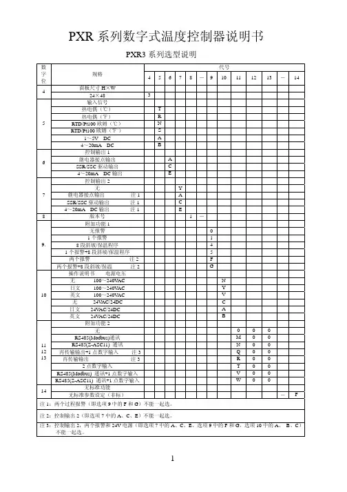
PXR 系列数字式温度控制器说明书PXR3系列选型说明 代号 数字位规格 45678-9101112 13 - 14面板尺寸H ×W 4 24×48 3 输入信号 热电偶(℃) T 热电偶(℉) R RTD/Pt100欧姆(℃) N RTD/Pt100欧姆(℉。
) S 1~5V DC A 54~20mA DC B 控制输出1 继电器接点输出 A SSR/SSC 驱动输出 C 64~20mA DC 输出 E 控制输出2 无 Y 继电器接点输出 注1 A SSR/SSC 驱动输出 注1 C 74~20mA DC 输出 注1 E 8版本号 1- 附加功能1 无报警 0 1个报警 1 8段斜坡/保温程序 4 1个报警+8段斜坡/保温程序 5 两个报警 注2 F 9.两个报警+8段斜坡/保温 注2 G 操作说明书 电源电压 无 100~240V AC N 日文 100~240V AC Y 英文 100~240V AC V 无 24V AC/24DC C 日文 24V AC/24DC A 10英文 24V AC/24DC B 附加功能2 无 0 0 0 RS485(Modbus)通讯 M 0 0 RS485(Z-ASC11) 通讯 N 0 0 再传输输出+1点数字输入 注3 Q 0 0 再传输输出 注3 R 0 0 2点数字输入 T 0 0 RS485(Modbus) 通讯+1点数字输入 V 0 0 111213RS485(Z-ASC11) 通讯+1点数字输入 W 0 0 无标准功能14 无标准参数设定(非标) - F 注1:两个过程报警(即选项9中的F 和G )不能一起选。
注2:控制输出2(即选项7中的A 、C 、E )不能一起选。
注3:控制输出2,两个报警和24V 电源(即选项7中的A 、C 、E 、选项9中的F 和G ,选项10中的A 、 B 、C )不能一起选。
PXR4系列选型说明 代号 数字位规格 45678-910 11 12 13面板尺寸W ×H 4 48×48mm 4 输入信号 热电偶(℃) T 热电偶(℉) R RTD/Pt100欧姆(℃) N RTD/Pt100欧姆(℉。
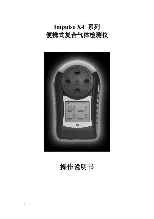
Impulse X4 系列便携式复合气体检测仪操作说明书!重要提示:!在首次使用仪器以前请认真阅读本手册,您将会掌握仪器正确的使用方法和了解仪器的功能,包括操作,维护,功能设置等内容。
!为了使操作者更安全,请按照手册中的要求,定期对仪器进行标定。
!如果在使用过程中,遇到的故障或问题在本手册中没有提到,请直接联系制造商Zellweger Analytics,或联系当地的代理商/服务商。
!警告和注意:·更换任何元器件都有可能损坏仪器的本质安全结构。
·如果需要使用存储卡,请选用Zellweger Analytics 提供的存储卡(订货号2566-0435),使用其它的存储卡有可能损坏仪器的本质安全结构。
·在允许的储存期之后激活检测器,有可能影响仪器的使用性能和保质期。
·应使用许可的5号干电池,如劲量电池,不要使用质量低下的干电池,以免影响仪器的本质安全性能。
·在更换电池时,应同时更换2节型号相同的新电池。
·在电池欠压提示后,应尽快更换新电池,以免旧电池漏液损坏仪器。
·在低温环境下,电池的寿命会缩短。
·更换电池时,应该在安全环境下进行。
·当更换任何一个传感器的情况下,都需要对仪器进行标定。
·在每天使用以前,应完成仪器的自检过程。
·定期的对仪器用标气进行测试,检查声、光、振动报警是否正常。
·标定时应选用厂家或国家认证合格企业提供的标准气体。
·标定时应在良好通风的环境下进行,以避免污染。
·不要在仪器电量不足的情况下标定。
·不要在富氧的环境下使用本仪器。
·可燃气体传感器的灵敏度会受到高浓度硫化物,卤素化合物,含硅化合物,以及含铅气体或蒸汽的影响,也叫“中毒”,应避免在以上的环境中使用仪器,如果必须使用,则使用完后应对仪器进行检测和标定,以免影响以后的使用。

PXR 系列数字式温度控制器说明书PXR3系列选型说明 代号 数字位规格 45678-9101112 13 - 14面板尺寸H ×W 4 24×48 3 输入信号 热电偶(℃) T 热电偶(℉) R RTD/Pt100欧姆(℃) N RTD/Pt100欧姆(℉。
) S 1~5V DC A 54~20mA DC B 控制输出1 继电器接点输出 A SSR/SSC 驱动输出 C 64~20mA DC 输出 E 控制输出2 无 Y 继电器接点输出 注1 A SSR/SSC 驱动输出 注1 C 74~20mA DC 输出 注1 E 8版本号 1- 附加功能1 无报警 0 1个报警 1 8段斜坡/保温程序 4 1个报警+8段斜坡/保温程序 5 两个报警 注2 F 9.两个报警+8段斜坡/保温 注2 G 操作说明书 电源电压 无 100~240V AC N 日文 100~240V AC Y 英文 100~240V AC V 无 24V AC/24DC C 日文 24V AC/24DC A 10英文 24V AC/24DC B 附加功能2 无 0 0 0 RS485(Modbus)通讯 M 0 0 RS485(Z-ASC11) 通讯 N 0 0 再传输输出+1点数字输入 注3 Q 0 0 再传输输出 注3 R 0 0 2点数字输入 T 0 0 RS485(Modbus) 通讯+1点数字输入 V 0 0 111213RS485(Z-ASC11) 通讯+1点数字输入 W 0 0 无标准功能14 无标准参数设定(非标) - F 注1:两个过程报警(即选项9中的F 和G )不能一起选。
注2:控制输出2(即选项7中的A 、C 、E )不能一起选。
注3:控制输出2,两个报警和24V 电源(即选项7中的A 、C 、E 、选项9中的F 和G ,选项10中的A 、 B 、C )不能一起选。
PXR4系列选型说明 代号 数字位规格 45678-910 11 12 13面板尺寸W ×H 4 48×48mm 4 输入信号 热电偶(℃) T 热电偶(℉) R RTD/Pt100欧姆(℃) N RTD/Pt100欧姆(℉。
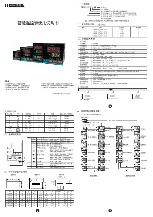
KKAI208C02A-A/0-201611234:(48*48)6:(96*48)7:(72*72)8:(48*96)9:(96*96)80:(80*160)16:(160*80)484872969616080A 型号H(Min)GBCDEF J 48967248968016097.597.597.597.597.596966.5999913139188.588.588.588.5838345.54567.59292155.5762525252525303045.59267.5459276155.54589.56744.591.575.5155K (Min)25252525253030面板尺寸 侧面尺寸 开孔尺寸J-0+0.5AI208系列E:版本10:单路输入B:一路报警输出 C: 两路报警 A: 无报警功能4: 48W*48H*100L 6:48W*96H*100L 7:72W*72H*100L 8:96W*48H*100L 9:96W*96H*100L AI208系列温控表R:继电器输出 S: 固态继电器输出 K:可控硅输出(需订做)序号型号主控方式2121报警路数1234SSR SSR RELAY RELAYAI208-4/6/7/8/9-SC10AI208-4/6/7/8/9-SB10AI208-4/6/7/8/9-RC10AI208-4/6/7/8/9-RB10智能温控表使用说明书本说明书对温控表设置、配线及各部分名称等进行说明,使用本产品前,请认真阅读本说明书,在理解内容的基础上正确使用。
并请妥善保存,以便需要时参考。
⊙支持多种热电偶、热电阻信号类型⊙采用模糊PID 控制算法,且自整定无过冲⊙多种控制方式可选,具体请参照OT 参数⊙RUN/STOP,运行/停止功能一键切换特点2、隔离模式框图:固态继电器输出绝缘电阻静电放电脉冲群抗扰度浪涌抗扰度电压暂降及短时中断抗扰度隔离耐压DC 24V 脉冲电平,带载<30mA 输入、输出、电源对机壳>20MΩIEC/EN61000-4-2 Contact ±4KV /Air ±8KV perf.Criteria B IEC/EN61000-4-4 ±2KV perf.Criteria B IEC/EN61000-4-5 ±2KV perf.Criteria BIEC/EN61000-4-29 0%~70% perf.Criteria B信号输入与输出及电源1500VAC 1min,60V 以下低压电路之间DC500V,1min 整机重量约 400g机壳材质面贴材质停电数据保护面板防护等级安全标准外壳与面板基架PC/ABS (难燃度UL94V-0)PET(F150/F200)10年,可写数据次数100万次IP65(IEC60529)IEC61010-1 过电压分类Ⅱ,污染等级2,等级Ⅱ(加强绝缘)3、测量信号参数表:1、电气参数表:采样速度2次每秒供电电源继电器容量AC 250V /3A 额定负载寿命大于10万次AC/DC 100~240V (85-265V)三、主要技术参数二、常规型号说明一、仪表型号周围环境条件整机功耗存贮环境< 6VA室内使用,温度:0~50℃ 无结露,湿度:<85%RH,海拔小于2000m -10~60℃,无结露□:外形尺寸可选注意:选择加热冷却控制方式时,如还需报警功能,请选择带两路报警的型号。
PXF5ACY2-FW100说明书PXF5ACY2-FW100富士温控器顾名思义,温度控制器是一种用来控制温度而无需操作人员的大量参与的仪器。
温度控制系统的控制器从热电偶或RTD等温度传感器接收输入信号后,将实际温度与所需控制温度或设定值进行比较。
然后将输出信号提供给控制元件。
例如,控制器从温度传感器接收输入信号,并将输出信号发送至所连接的加热器或风扇等控制元件。
控制器通常只是整个温度控制系统的一部分,因此在选择适当的控制器时,应对整个系统进行分析和考量。
温控器(Thermostat),根据工作环境的温度变化,在开关内部发生物理形变,从而产生某些特殊效应,产生导通或者断开动作的一系列自动控制元件,或者电子原件在不同温度下,工作状态的不同原理来给电路提供温度数据,以供电路采集温度数据。
流体媒介温度控制器是利用感温流体热胀冷缩及液体不可压缩的原理而实现自动调节。
当控制温度升高时感温液体膨胀产生的推力将热媒关小,以降低输出温度;当控制温度降低时感温液体收缩,在复位装置的作用下将热媒开大,以提高输出温度,从而使被控制的温度达到和保持在所设定的温度范围内。
双金属片温控器工作原理根据物体热胀冷缩原理。
热胀冷缩是物体的共性,但不同物体其热胀冷缩的程度不一样。
双金片的两面是不同物质的导体,在变化的温度下由于胀缩程度不一样而使双金片弯曲,碰到设定的触点或开关,使设定的电路(保护)开始工作。
色温型温控器,工作原理系采用一些涂料在不同的温度下会产生不同的色彩的原理。
比如用液晶在不同温度下,就可以产生不同的颜色,再用摄像头类的色彩采集器以给电路提供不同的数据,从而对电路进行控制。
PXF5ACY2-FW100富士温控器一、PXR型数字温控表的功能特点如下:1. 前面板IP66防水结构,三健式菜单操作;2.标准螺钉接线,无须插座;3. 纵向尺寸比PXW表更短;4. UL/CSA/CE认证标志;5. 测量值大LED红色显示;6. 控制功能多种:简单ON/OFF控制,PID带自动调节控制,模糊及PID带自动调节控制,PID自适应调节控制;7.再传输功能(选件):传感器测量值可以以4-20MA型式传送到PHR型数据记录仪,PLC及个人计算机中;8. 8段斜坡/保温程序控制功能(选件);9. RS-485通讯功能(选件),可与FUJI POD及个人计算机通讯;10.数字输入控制功能(选件):通过一点开关量ON/OFF,可改变设定值SV,控制动作起/停,斜坡/保温控制的开始/ 复位,自动调节功能的起/停,报警锁存的复位、定时器计时开始;11. 加冷却控制(选件):有利于节能;12. 加热断线报警(选件);13. 两点各种报警功能(选件):值报警,区间报警,偏差报警;14. 具有塑机的模糊+PID控制功能:15. 内部定时器功能有机械式的和电子式的,机械式的采用两层热膨胀系数不同金属压在一起,温度改变时,他的弯曲度会发生改变,当弯曲到某个程度时,接通(或断开)回路,使得制冷(或加热)设备工作。
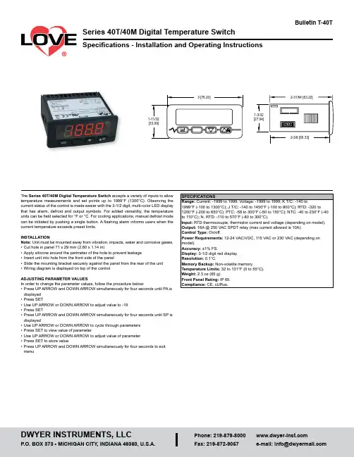
The Series 40T/40M Digital Temperature Switch accepts a variety of inputs to allow temperature measurements and set points up to 1999°F (1300°C). Observing the current status of the control is made easier with the 3-1/2 digit, multi-color LED display that has alarm, defrost and output symbols. For added versatility, the temperature units can be field selected for °F or °C. For cooling applications, manual defrost mode can be initiated by pushing a single button. A flashing alarm informs users when the current temperature exceeds preset limits.INSTALLATIONNote: Unit must be mounted away from vibration, impacts, water and corrosive gases.• Cut hole in panel 71 x 29 mm (2.80 x 1.14 in)• Apply silicone around the perimeter of the hole to prevent leakage • Insert unit into hole from the front side of the panel• Slide the mounting bracket securely against the panel from the rear of the unit • Wiring diagram is displayed on top of the controlADJUSTING PARAMETER VALUESIn order to change the parameter values, follow the procedure below:• Press UP ARROW and DOWN ARROW simultaneously for four seconds until PA is displayed • Press SET• Use UP ARROW or DOWN ARROW to adjust value to -19• Press SET• Press UP ARROW and DOWN ARROW simultaneously for four seconds until SP is displayed• Use UP ARROW or DOWN ARROW to cycle through parameters • Press SET to view value of parameter• Use UP ARROW or DOWN ARROW to adjust value of parameter • Press SET to store value• Press UP ARROW and DOWN ARROW simultaneously for four seconds to exit menuWIRINGAvoid installing the temperature probe cables in close proximity of any power cables. If the length of the probe cables is longer than 100 meters, a recalibration adjustment may be made using the CA1 parameter.ELECTRIC SYSTEMPOWER SUPPLYPTC/NTC PROBES12111091211121110121112IN COM COM IN CP COM COM IN 12 V R O O MR O O MR O O MR O O MJ/KTHERMOCOUPLES2/3 WIRES PT 100,PT 1000 AND NI 120 PROBES 0-20/4-20 mA AND 0-10/2-10 VACTIVE TRANSDUCERS2/3 WIRES 4-20 mAPASSIVE TRANSDUCERSIN 111097654321M A X . 10 AK 1L O ADPARAMETER DESCRIPTIONSP Sets ambient temperature set point between r1 and r2CA1Ambient probe calibration adjustmentP0P1 Position of decimal placeP2 Display engineering units0 °C1 °F2 No unitsP3Minimum value for process inputP4Maximum value for process inputP5Value shown during normal operation0 Probe temperature1 Set pointr0Set point differential or hysteresisr1Minimum value for set pointr2Maximum value for set pointr3 Set point lock out0 Unlocked1 Lockedr5 Selection of heating/cooling operation0 Cooling1 HeatingC1Minimum time between compressor startsC2 Minimum time compressor must remain off before being restartedC3Minimum time compressor must remain on after being startedC4During probe error, time compressor is offC5During probe error, time compressor is ond0Interval of time between defrost cycles (if 0, defrost will never be activated) d3 Duration of defrost cycled4Start defrost cycle upon power up0 No1 Yesd5Defrost delay time upon power up (d4 must be 1)d6 Temperature shown during defrost0 Display probe temperature1 = Display probe temperature up to (set point + r0) if probe temperatureis below (set point + r0) at activation of defrost cycle. Display probetemperature if the probe temperature is above (set point + r0) at activation of defrost cycle.A1Alarm 1 temperature set pointA2Alarm 1 not activated unless temperature remains in alarm state for this timeA3 Alarm 1 type0 Alarm disabled1 Absolute low alarm (A1)2 Absolute high alarm (A1)3 = Deviation low alarm (SP - A1)4 = Deviation high alarm (SP + A1)A4Temperature alarms not activated for this time after modifications to setpointA5Alarm 2 temperature set pointA6Alarm 2 not activated unless temperature remains in alarm state for thistimeA7 Alarm 2 type0 Alarm disabled1 Absolute low alarm (A1)2 Absolute high alarm (A1)3 = Deviation low alarm (SP - A1)4 = Deviation high alarm (SP + A1)E9 ReservedPrinted in U.S.A. 7/23FR# 443741-00 Rev. 7©Copyright 2023 Dwyer Instruments, LLC DISPLAYING ROOM TEMPERATUREIf the P5 parameter is set to display the temperature set point, the probe temperature can be displayed by pressing the DOWN ARROW key for two seconds until Pb1 is displayed. Next, hit the SET key. To return to the normal display, press SET key.MANUAL DEFROST ACTIVATION/DEACTIVATIONTo manually activate the defrost cycle, press the UP ARROW key for four seconds. This feature is disabled during heating operation.PARAMETER LOCK OUT ACTIVATION/DEACTIVATIONThe key pad lock out can be activated/deactivated by pressing the SET and DOWN ARROW keys simultaneously for two seconds. The display will flash Loc or UnL to signify the change in states.ALARM BUZZER RESETThe audible alarm can be silenced by pressing any key.RESTORING FACTORY DEFAULT SETTINGSFactory settings can be restored by following the below procedure:• Pressing the UP ARROW and DOWN ARROW keys for four seconds until PA is displayed• Press the SET key• Press the UP ARROW or DOWN ARROW to adjust the value to 743• Press SET key• Pressing the UP ARROW and DOWN ARROW keys for four seconds until dEF is displayed• Press SET key• Press the UP ARROW or DOWN ARROW to adjust the value to 149• Press SET key• Cycle the power after the flashing dEF goes awayMAINTENANCE, CLEANING AND REPAIRAfter final installation of the unit no routine maintenance is required. Clean the surface of the display controller with a soft and damp cloth. Never use abrasive detergents, petrol, alcohol or solvents. A periodic check of the system calibration is recommended. The Series 40T/40M is not field serviceable and should be returned if repair is needed (field repair should not be attempted and may void warranty). Be sure to include a brief description of the problem plus any relevant application notes. Contact customer service to receive a return goods authorization number before shipping.°C °F Loc。
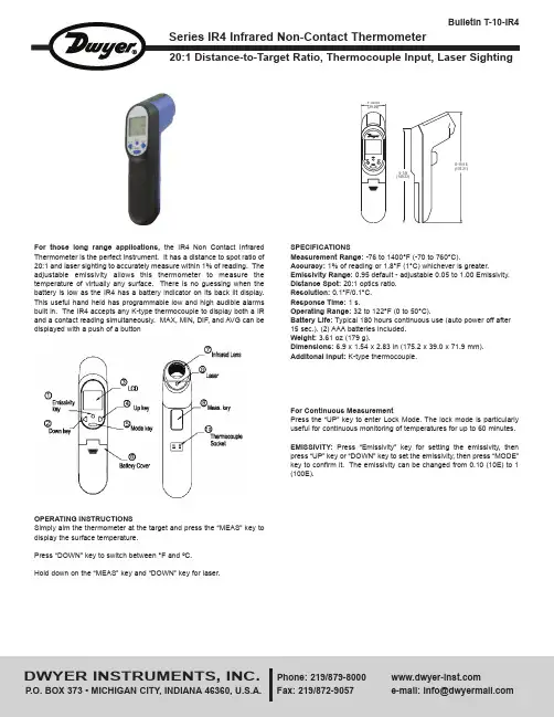
Forthose long range applications, the IR4 Non Contact Infrared Thermometer is the perfect instrument. It has a distance to spot ratio of 20:1 and laser sighting to accurately measure within 1% of reading. The adjustable emissivity allows this thermometer to measure the temperature of virtually any surface. There is no guessing when the battery is low as the IR4 has a battery indicator on its back lit display.This useful hand held has programmable low and high audible alarms built in. The IR4 accepts any K-type thermocouple to display both a IR and a contact reading simultaneously. MAX, MIN, DIF, and AVG can be displayed with a push of a buttonOPERATING INSTRUCTIONSSimply aim the thermometer at the target and press the “MEAS” key to display the surface temperature.Press “DOWN” key to switch between °F and ºC.Hold down on the “MEAS” key and “DOWN” key for laser.SPECIFICATIONSMeasurement Range:-76 to 1400°F (-70 to 760°C).Accuracy: 1% of reading or 1.8°F (1°C) whichever is greater.Emissivity Range: 0.95 default - adjustable 0.05 to 1.00 Emissivity.Distance Spot: 20:1 optics ratio.Resolution: 0.1°F/0.1°C.Response Time: 1 s.Operating Range: 32 to 122°F (0 to 50°C).Battery Life: Typical 180 hours continuous use (auto power off after 15 sec.). (2) AAA batteries included.Weight: 3.61 oz (179 g).Dimensions: 6.9 x 1.54 x 2.83 in (175.2 x 39.0 x 71.9 mm).Additonal Input:K-type thermocouple.For Continuous MeasurementPress the “UP” key to enter Lock Mode. The lock mode is particularly useful for continuous monitoring of temperatures for up to 60 minutes.EMISSIVITY: Press “Emissivity” key for setting the emissivity, then press “UP” key or “DOWN” key to set the emissivity, then press “MODE”key to confirm it. The emissivity can be changed from 0.10 (10E) to 1(100E).Function:Press the “MODE” key for scrolling to display more functions as follows.E: Will show the emissivity data.MAX, MIN DIF,AVG: Press“MODE” keyfor the Maximum (MAX),Difference between MAX and MIN (DIF) and Average (AVG) modes.During the measurement, the special modes reading will be displayed beside the mode icon.HAL, LAL: Press “UP” key or “DOWN” key to change the High Alarm (HAL) or Lo Alarm (LAL) then press “MEAS” key to confirm it.PRB:Connect the thermocouple to the thermocouple socket and put the probe in/on the target to be measured, the thermometer will display the temperature automatically without pressing any button. To see the minimum or maximum data during the probe measurement, please hold down the “UP” key or “DOWN” key.After measuring high temperatures the probe may remain HOT for a while.LED Error MessagesThe thermometer incorporates visual diagnostic messages as follows.“HI/LOW”: “Hi” or “Lo” is displayed when the temperature being measured is outside of the settings of HAL and LAL.“Er2”: Displays when the thermometer is exposed to rapid changes in the ambient temperature.“Er3”: Displays when the ambient temperature exceeds 32°F (0°C) or 122°F (50°C). The thermometer should be allowed plenty of time (minimum 30 minutes) to stabilized to the working/room temperature.For all other error messages it is necessary to reset the thermometer. To reset it, turn the instrument off, remove the battery and wait for a minimum of one minute, reinsert the battery and turn it on. If the error message remains please contact the Dwyer Customer Service department for further assistance.Batteries:The thermometer incorporates visual low battery indication as follows.Battery OK: Measurements are possible.Battery Low:Battery needs to be replaced, measurements are still possible.Battery Exhausted: Measurements are not possible. When the low battery icon indicates the battery is low, the batteries should be replaced immediately with AAA, 1.5V batteries.Please Note:It is important to turn the thermometer off before replacing the battery otherwise the thermometer may malfunction. Dispose of used battery promptly and keep away from children.CAUTION1. When device is in use, do not look directly into the laser beam - Permanent eye damage may result.e extreme caution when operating the laser.3.Never point the device towards anyone’s eyes.4.Keep out of reach of all children.EMC/RFIReadings may be affected if the unit is operated within radio frequency electromagnetic field strength of approximately 3 volts per meter, but the performance of the instrument will not be permanently affected. **Note:under the electromagnetic field of 3V/m from 350 to 550 MHz, the maximum error is 14.4˚F (8˚C).MAINTENANCEA periodic check of the system calibration is recommended. The Series IR4 is not field serviceable and should be returned if repair is needed (field repair should not be attempted and may void warranty). Be sure to include a brief description of the problem plus any relevant application notes. Contact customer service to receive a return goods authorization number before shipping.Storage and CleaningThe sensor lens is the most delicate part of the thermometer. The lens should be kept clean at all times, care should be taken when cleaning the lens using only a soft cloth or cotton swab with water or medical alcohol.Allowing the lens to fully dry before using the thermometer. Do not submerge any part of the thermometer. The thermometer should be stored at room temperature between -4 and 149ºF (-20 to 65ºC).page 2©Copyright 2014 Dwyer Instruments, Inc.Printed in U.S.A. 5/14FR # R7-443521-00 Rev. 1。
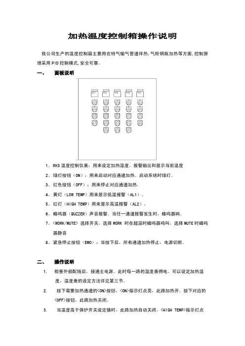
加热温度控制箱操作说明我公司生产的温度控制箱主要用在特气输气管道伴热,气柜钢瓶加热等方面,控制原理采用PID控制模式,安全可靠。
一、面板说明1、RKS温度控制仪表:用来设定加热温度,报警输出和显示当前温度2、绿灯按钮(ON):用来启动对应通道加热。
启动系统时绿灯。
3、红色按钮(OFF):用来停止对应通道加热。
4、黄灯(LOW TEMP)用来显示低温报警(AL1)。
5、红灯(HIGH TEMP)用来显示高温报警(AL2)。
6、蜂鸣器(BUZZER)声音报警。
当任一通道报警发生时,蜂鸣器响。
7、<WORK/MUTE> 选择开关,选择WORK 时在超温时蜂鸣器鸣叫,选择MUTE时蜂鸣器静音8、紧急停止按钮(EMO):当按下后,所有通道加热停止,电源切断。
二、操作说明1.检查外部配线后,接通主电源。
此时每一路的温度表得电,可以设定加热温度,温度表的设定方法详见第三节。
2. 按下需要加热通道的<ON>按钮,<ON>指示灯点亮,此路加热开。
按下对应的<OFF>按钮,此路加热关闭。
3. 当温度高于保护开关设定值时,此路加热自动关闭,<HIGH TEMP>指示灯点亮,蜂鸣器鸣叫。
4.加热自动关闭后温度会慢慢降低,当温度低于保护器设定值时<HIGH TEMP>指示灯熄灭,蜂鸣器静音。
此时如果需要加热,要重新按下<ON>按钮。
5.遇到紧急情况请按下<EMS STOP>按钮,关闭所有加热。
紧急按钮复位后需要重新按<ON>按钮开启加热。
三、温度控制器参数设定一般情况下设好温度,系统开始运行,就不需要再修改里面的参数了。
如果只是想调节控制的目标温度,只要按动向上或向下的键就可以修改SV值(SV为控制温度,PV为当前显示温度)。
具体操作参照RKS仪表自带的产品说明书,这里做一些常用参数的设定介绍:1、按最右边模式键三秒钟会出现一菜单栏。
记录仪数据管理软件安装与使用指南2014-1-6目录目录1 产品简介.............................................................................................................. .. .. (3)2 运行环境要求 (3)3 安装USB驱动........................... ........................ .................................. .. .. (3)4 详细安装过程......................................... ........................ .......... .. (3)4.1 运行安装程序......................................................................................... ......... .. (3)4.2 选择安装语言.................................................... ......... . (4)4.3安装目录选择界面. . (4)4.4添加开始菜单 (5)4.5添加附加任务 (5)4.6 开始安装 (6)4.7安装其他运行组件 (6)5 使用简介. . . .......................................... ........................ .......... .. ............................... .. (7)5.1 主界面......................................................................................... .. (7)5.2 连接按钮.......................................... ......... .. (7)5.3 上传按钮. . ......................................................................................................... .. (8)5.4 参数设置按钮.................................................................................................... (12)5.5 系统设置按钮 . . . . . . . . . . . . . . . . . ............................................................................. .155.6 查询按钮... ..... ..... ..... .... ..... ..... ..... .... ..... ..... ..... .... ..... ..... ..... .... ..... ..... ..... .... ..165.7 保存按钮... ..... ..... ..... .... ..... ..... ..... .... ..... ..... ..... .... ..... ..... ..... .... ..... ..... ..... .... ..175.8 导出EXCEL按钮... ..... ..... ..... .... ..... ..... ..... .... ..... ..... ..... .... ..... ..... ..... .... ..... .... ..175.9 导出PDF按钮... ..... ..... ..... .... ..... ..... ..... .... ..... ..... ..... .... ..... ..... ..... .... .......... .... ..175.10 导出WORD按钮... ..... ..... ..... .... ..... ..... ..... .... ..... ..... ... ..... ..... .... ..... ..... ..... .... ..175.11 导出TXT按钮... ..... ..... ..... .... ..... ..... ..... .... ..... ..... ..... .... ..... ..... ..... ........ ..... .... ..175.12 打印按钮... ..... ..... ..... .... ..... ..... ..... .... ..... ..... ..... .... ..... ..... ..... ........ ..... .... . (17)5.13 删除按钮... ..... ..... ..... .... ..... ..... ..... .... ..... ..... ..... .... ..... ..... ..... ........ ..... ........... ..175.14 发邮件按钮... ..... ..... ..... .... ..... ..... ..... .... ..... ..... ..... .... ..... ..... ..... ........ ..... …... ..175.15 停止按钮... ..... ..... ..... .... ..... ..... ..... .... ..... ..... ..... .... ..... ..... ..... ........ ..... ........... ..18记录仪数据管理软件安装与使用指南1、产品简介记录仪数据管理软件是我司开发的最新一代记录仪产品配套的分析软件。
− 1 −
− 2 −
注) 上段(PV)显示消失(无显示)时,请在参数DP13的设定值上加64。
2接线
3使用方法(请在使用前阅读)
6关于温度调节器的功能
− 3 −
− 4 −
7为熟练使用温度调节器
Modbus RTU 是modicon 公司的商标。
8请在显示异常时阅读
* DC4-20mA 输入时,除使用250Ω的外置电阻外,还请作为DC1-5V 输入使用。
注1) 仅同一类型中可以变更代码。
注1) 输入精度为±0.5%FS±1digit±1°C 。
但,采用热敏电阻时,则为±1%FS±1digit 。
R 热电偶0~500°C
B 热电偶0~400°C
注2) 采用测温电阻时,即使低于-150°C ,也不显示LLLL 。
注3)
设定低于上表的最小量程时,不能保证输入精度。
的范围内,有时由于传感器的特性,不能正确显示。
*1 微型控制器X 系列与其他机型的不同点如下表所示,请加以注意。
*2 连接计算机时,需要通信变换器。
另行准备(推荐产品) (株)RA 系统公司生产 RC-77(隔离型) http://www.ras.co.jp (株)lineeye 公司生产 SI-30A(隔离型) http://www.lineeye.co.jp (株)系统sacom 公司生产 KS485(非隔离型) http://www.sacom.co.jp 规 格
电源电压:AC100(-15%)~240V(+10%)、50/60Hz 、DC/AC 24V(±10%)
功耗
:10VA 以下(AC100V),12VA 以下
(AC220V),12VA 以下(AC/DC24V)继电器接点输出
:控制输出1 1c 接点AC220V/DC30V ,3A(阻性负载)控制输出2 1a 接点AC220V/DC30V ,3A(阻性负载)
SSR/SSC 驱动输出*1(电压脉冲输出):ON 时 DC24V(DC17~25V)OFF 时 DC0.5V 以下
最大电流 DC20mA 以下负载电阻 850Ω以上
DC4-20mA 输出:容许负载电阻 600Ω以下报警输出(最多2点):继电器接点(1a 接点) AC220V/DC30V 1A(阻性负载)加热器断线报警输出:继电器接点(1a 接点) AC220V/DC30V 1A(阻性负载)通信功能*2:RS-485接口
传输方式/半双工位串行起止同步传输速度/9600bps
通信协议/符合Modbus RTU 或Z-ASCII (PXR 协议)传输距离/最大500m(连接总长度)连接台数/31台
数字量输入:输入点数2点 (ON 判定:DC3V 以上,OFF 判定:DC2V 以下)
输入接点容量 DC5V / 2mA 输入脉冲宽度 最小0.5秒
传送输出:输出精度 ±0.3%以下
容许负载电阻 600Ω以下
远程SV 输入:输入精度 ±0.5%FS 以下(无输入断线检测功能)
设定分辨率 3000以上带输入滤波功能
使用及贮存温度:-10°C ~50°C ,90%RH 以下(无结露)
-10°C ~45°C(密集安装时)-20°C ~60°C(贮存温度)
时间精度:±0.5%
以内SSR/SSC 驱动输出DC4-20mA 输出容许负载电阻
电压最大电流PXR3DC15V 20mA 100~500ΩPXR4/5/7/9DC24V 20mA 600Ω以下PXV3DC5.5V 20mA 600Ω以下PXV/W/Z DC24V 60mA 600Ω以下
[所谓过量程方向]
输入在范围之外或异常时的输出方向。
下限:OFF 或4mA 以下上限:ON 或20mA 以上
[双重输出型的注意事项](选项)
(1) 不能独立于加热/冷却对I.D 动作进行设定。
(2) 如果加热侧进行双位动作,冷却侧也将进行双位动作。
(3) 如果设定CooL =0.0,则冷却侧为ON/OFF 动作。
此时,ON/OFF 动作的滞后将固定(0.5%FS)。
注) 待机时也为输入过量程时,将按照本参数的指定进行输出。
注) · 变更了报警动作种类时,请确认报警设定。
报警设定值可能因变更而发生变化,这并非异常。
· 变更报警种类后,请将本体的电源切断后重新接通。
· 报警动作种类代码12~15输出至AL2继电器。
· ALn :表示AL1、AL2、AL3报警设定值。
· An-H :表示A1-H 、A2-H 、A3-H 报警设定值。
· An-L :表示A1-L 、A2-L 、A3-L 报警设定值。
· dL Yn :表示dL Y1、dL Y2、dL Y3报警延时ON 设定值。
[各项功能说明]
1. 通电启动:从当前的PV 值开始启动斜坡-保温。
2. END 时输出:表示斜坡-保温为END 时的输出状态。
3. OFF 时的输出:表示斜坡-保温为OFF 时的输出状态。
4. 重复动作:一旦斜坡-保温的最终段结束,即重新启动斜坡-保温,反复动作。
通常(无重复动作),保持最终段所设定的PV 值。
※ 待机模式: 输出-3% 报警OFF 完全不进行控制动作的待机模式
所谓保持功能
是指接通电源时,测量值即使在报警范围之内,也不立即使报警ON ,待离开报警的范围并再次进入报警范围内时才发生报警。
([MOD 代码一览表]MOD 通电启动END 时输出OFF 时输出重复动作0无继续控制继续控制无1无继续控制继续控制有2无继续控制待机模式无3无继续控制待机模式有4无待机模式继续控制无5无待机模式继续控制有6无待机模式待机模式无7无待机模式待机模式有8有继续控制继续控制无9有继续控制继续控制有10有继续控制待机模式无11有继续控制待机模式有12有待机模式继续控制无13有待机模式继续控制有14有待机模式待机模式无15
有
待机模式
待机模式
有
eԪ ՐὋ ͳ Ѭ Ր nj
代码(P-n1)输出类型
控制动作过量程方向
输出1 输出2输出1 输出20单输出
反动作
—
下限—
1上限
2正动作
下限3上限4双重输出
反动作
正动作
下限
下限
5上限6下限
上限
7上限8正动作
下限
下限
9上限10下限
上限
11上限12反动作
反动作
下限
下限
13上限14下限
上限
15上限16正动作
下限
下限
17上限18下限
上限
19
上限。