MTC10使用手册
- 格式:ppt
- 大小:945.00 KB
- 文档页数:25
目录实验一断面交通量与交通组成调查 (3)一.实验目的 (3)二.实验设备 (3)三.实验原理 (3)四.实验内容 (4)五.实验安排 (6)六.注意事项 (6)七.实验报告 (6)实验二路口转向交通量与车头时距调查 (7)一.实验目的 (7)二.实验要求 (7)三.实验设备 (7)四.实验原理与步骤 (8)五.实验安排 (8)六.注意事项 (8)七.实验报告 (9)实验三交叉口延误与饱和流率调查 (10)一.实验目的 (10)二.实验要求 (10)三.实验设备 (10)四.实验原理与步骤 (11)五.实验安排 (12)六.注意事项 (12)七.实验报告 (13)实验四公交站通行能力调查 (14)一.实验目的 (14)二.实验任务 (14)三.实验设备 (14)四.实验要求 (15)五.实验安排 (15)六.实验报告 (15)实验五公交线路上下乘客分布及延误调查 (17)一.实验目的 (17)二.实验任务 (17)三.实验设备 (17)四.实验要求 (18)五.实验安排 (18)六.实验报告 (18)实验六视频交通数据采集实验 (20)一.实验目的 (20)二.实验设备 (20)三.实验原理 (20)四.实验流程 (21)五.实验安排 (21)六.注意事项 (21)七.实验报告 (21)实验七车速调查实验 (22)一.实验目的 (22)二.实验仪器设备 (22)三.实验原理 (22)四.实验要求 (23)五.实验流程 (24)六.人员安排 (27)七.实验思考 (27)实验一断面交通量与交通组成调查一.实验目的1. 掌握MC5600型气压管交通检测器、MMU51便携式交通流车辆分析仪的使用方法。
2. 掌握MMC5600型气压管检测器数据处理系统的使用方法。
3. 了解MC5600型气压管检测器、MMU51便携式交通流车辆分析仪的基本工作原理。
4. 了解MC5600型气压管检测器、MMU51便携式交通流车辆分析仪的特点及适用范围。


MODEL010CWIND SPEED SENSOROPERATION MANUALMet One Instruments, IncCorporate Sales & Service: 1600 NW Washington Blvd. Grants Pass, OR 97526 Tel (541) 471-7111 Fax (541) 471-7116******************1.0 GENERAL INFORMATION1.1 The 010C Wind Speed Sensor uses a durable, three-cup anemometer assembly andsolid-optical link with a 40-slot chopper disk to produce a pulsed output whosefrequency is proportional to wind speed. An internal heater reduces moisture forextended bearing life. This sensor is usually used in conjunction with the 191 Cross arm Assembly. The sensor may be used with a translator module, or used directlywith a variety of data loggers.1.2 The Sensor Cable has a quick-connect connector with vinyl jacketed, shielded cable.Cable length is given in -XX feet on each cable part number. A 1953-XX cable isused with translators having terminal strip connections.Table 1-1Model 010C Wind Speed Sensor SpecificationsPerformance CharacteristicsMaximum Operating Range 0-60 meters/sec or 0-125 mphStarting Speed 0.27 meters/sec or 0.6 mphCalibrated Range 0-50 meters/sec or 0-100 mphAccuracy ±1% or 0.15 mphTemperature Range -50︒C to +85︒CResponse Distance constant less than 5 ft of flow**The distance traveled by the air after a sharp-edged gust has occurred for theanemometer rate to reach 63% of the new speed. Distant constant less than 15ft of flow with optional 010C-1 aluminum cupset.Electrical CharacteristicsPower Requirements 12 VDC at 10 mAOutput Signal 11-volt pulseOutput Impedance 100 ohms maximumHeater Power Requirement 12 VDC at 350 mAStandard Cable Length 300’ maximum (consult factory if longercable is to be used for special requirements) Physical CharacteristicsWeight 1.1 poundsFinish Anodized aluminumMounting Use with 191 CrossarmCabling 1953-XX Cable (XX is cable length in feet)Optional AccessoriesA. External heater and power supply for extreme low temperature operation.B. Ice Skirt for extreme icing environments.C. Aluminum cup assembly.2.0 INSTALLATION2.1 The 010C Wind Speed InstallationA. Mount the cup assembly and secure with the Allen head set screw, check to seethat the cup assembly rotates freely.B. Install the sensor in the end of the Model 191 Crossarm Assembly (the endwithout the bushing).C. Tighten the locking set screw. Do not over-tighten. Apply a small amount ofsilicone grease to set screws to prevent freezing in adverse environments.D. Connect the cable assembly to the keyed sensor receptacle and tape it to themounting arm.2.2 WiringA. The cable assembly contains five wires. Typical wiring hookup is shown inFigure 2-1.No Connection White/Brown ShieldElectrical ConnectorView looking at connector pins. (Pins are also identified on connector).2.3 Lightning ProtectionA. Weather sensors are sensitive to direct or nearby lightning strikes. A well-grounded metal rod or frame should be placed above the sensor installation. Inaddition, the shield on the signal cable leading to the translator must beconnected to a good earth ground at the translator end and the cable routeshould not be vulnerable to lightning.3.0 OPERATIONAL CHECK-OUT AND CALIBRATION3.1 010C Wind Speed Sensor Check-OutA. Spinning the anemometer cup assembly will produce a series of pulses (40pulses per revolution). To verify sensor output, monitor this signal with either thetranslator module, data logger, or an oscilloscope. (Refer to Frequency vs. WindSpeed Table 3-1). Spinning the hub of the wind speed transmitter without thecup assembly mounted and allowing it to coast to a stop will give a goodindication of threshold performance; a jerky or sudden stop indicates damage tobearings, bent drive shaft, or obstruction in the light chopper.B. Inspect the cup assembly for loose cup arms or other damage. The cupassembly cannot change calibration unless a mechanical part has come loose orhas been broken. If a cup arm is loose or broken the calibration of the sensormay be affected.C. If the sensor heater is used, check internal heater operation by sliding sensorcover down and touching the housing behind the printed circuit board. Thehousing should feel warmer than the adjoining metal parts. The sensor has abuilt-in heater that is designed to provide a raise in the internal temperature,providing a small amount of positive pressure. This heater requires as external12 V (@500ma) power supply.FREQUENCY vs WIND SPEED FOR 010 SENSORTABLE 3-1Transfer FunctionsMiles per hour: Meters per second:rpm = 16.767 * (V mph - 0.6) rpm = 37.522 * (V m/s - 0.27) V mph = (rpm / 16.767) + 0.6 V m/s = (rpm / 37.522) + 0.27 f Hz = (V mph - 0.6) / .08946 f Hz = (V m/s - 0.27) / 0.039976 V mph = V m/s * 0.44704 V m/s = V mph / 0.447044.0 MAINTENANCE AND TROUBLESHOOTING4.1 General Maintenance Schedule*6 – 12 Month Intervals:A. Inspect sensor for proper operation per Section 4.2.B. Replace wind speed sensor bearings in extremely adverse environments perSection 4.5.12 – 24 Month Intervals:A. Recommended complete factory overhaul of sensor.*Schedule is based on average to adverse environments.Table 4-1010C Wind Speed Sensor TroubleshootingSymptom Probable Cause Solution Refer toNo wind speed output Loss of supplyvoltage Check translator +12supply & connectingcablesFigure 2-1Faulty integratedamplifierReplace circuit board Section 4.5Faulty diodes,D1, D2Replace circuit board Section 4.5Faulty detector Replace detector Section 4.6No wind speed outputbelow 2-5 mphBad bearing(s) Replace bearing(s) Section 4.4Faulty detector Replace detector Section 4.6Wind speed signal drops ouas speed increasesFaulty detector Replace detector Section 4.64.2 010C Wind Speed Sensor: 6 – 12 Month Periodic ServiceA. At the crossarm assembly, disconnect the quick disconnect plug from the sensor(leave the cable secured to the crossarm) and remove the sensor from thecrossarm assembly.B. Loosen the set screw holding the cup assembly. Support the rotating hub of thesensor with one hand and pull the anemometer cup assembly free.C. Visually inspect the anemometer cups for cracks and breaks. Also, make surethat each arm is securely attached to the cup assembly hub.D. Slide the sensor cover down to expose the light-chopper disc assembly, lightsource, detector, and circuit board.E. Inspect the interior of the sensor for any signs of corrosion and/or dust buildup.F. Inspect the light-chopper for cracks, and make sure that all slots are free ofcorrosion.G. Inspect the signal-conditioning module for cracks and corrosion around solderedconnections.H. Rotate the sensor hub assembly to ensure that it turns freely and that the sensorbearings are not damaged. Make sure the light-chopper assembly is notcontacting the light source and detector.I. Apply a small amount of silicone lubricant. (Dow-Corning DC-33 or equivalent) tothe sensor O-ring seals; slide the cover up over the sensor and wipe off anyexcess lubricant.J. A moisture vent is located on the base of the sensor; make sure that this vent is clear.K. Re-install sensor according to installation procedure (Section 2.0); verify proper operation using procedures in Section 3.0.4.3 010C Wind Speed Sensor Maintenance (Refer to 010C Sensor Assembly Drawing)The following procedures require a relatively clean, dry work area, a source of 12VDC power at approximately 20 mA, and an oscilloscope (DC to 10 KHz minimumrange required.4.4 Sensor Bearing Replacement. (Refer to 010C Sensor Assembly Drawing)A. Remove sensor from tower and remove cup assembly (1). Refer to Section 4.2.B. Disassemble sensor and remove old bearings (6).1. Slide the sensor cover (16) down to expose the light-chopper discassembly (10), detector assembly (12) and circuit board (18).2. Loosen both special set screws on the shaft of the light chopper assembly(11).3. Support the light-chopper assembly (10) with one hand and slowly pullthe rotating hub/shaft assembly (2) out of the column (8).4. Remove the shield (4) and slinger (5) from the column (8).5. Remove the light-chopper assembly (10) from the sensor housing, beingcareful not to damage the slots located between the light-chopper holderand the lower bearing.6. Insert the lower end of the rotating hub/shaft assembly into the upperbearing, cock it slightly to one side and push out the lower bearing.7. Insert a right-angle type of tool, such as an Allen wrench, into the upperbearing; cock it slightly to one side and remove the bearing.8. Clean dirt from bearing bores, using a cotton swab and alcohol.C. Install the new bearings and assemble the sensor.1. Install new upper and lower bearings in the column (8). Bearings shouldslide easily into bearing bores.2. Install a slinger and shield (4, 5) on the column assembly. Use new partsif old ones are damaged or corroded.3. Insert the rotating hub shaft (2) into the column assembly (8), through theshield (4), slinger, and upper bearing, until it starts to protrude through thelower bearing.4. Support the light-chopper assembly (10) with one hand and slowly pushthe rotating hub shaft into it until the shaft almost touches the bottom.5. Tighten both special set screws on the light-chopper assembly; do notover tighten as the set screw tips will damage the shaft.6. Rotate the sensor hub assembly (2) to ensure that it turns freely and thatan endplay of about .005” exis ts.7. Hold sensor vertically and make sure that the light-chopper assembly (10)is not contacting the detector assembly (12).8. Apply small amount of silicone lubricant (Dow-Corning DC-33 orequivalent) to the sensor O-rings (9); slide the cover (16) up over thesensor and wipe off any excess lubricant.D. Replace cup assembly and re-install (refer to Section 2.0)4.5 1200-1 Circuit Board Assembly Replacement (Refer to 010C Assembly Schematic)A. Remove sensor from tower and remove cup assembly (refer to Section 4.2).B. Slide the sensor cover (16) down to expose the light-chopper disc assembly (10),detector assembly (12), and circuit board (18).C. Remove two screws (17) holding circuit board assembly (18) and lift circuit boardaway from sensor housing.D. Note color of wires and then unsolder wires to detector assembly from circuitboard and three wires from connector (19).E. Install new circuit board assembly by reversing above procedure.4.6 Detector Assembly Replacement Refer to 010C Assembly Schematic)NOTE: 010C sensors SN M10560 and later use 520253 photodetector. Oldersensors use 1074 photodetector assemblies.A. Remove sensor from tower and remove cup assembly. Refer to Section 4.2.B. Slide the sensor cover (16) down to expose the light-chopper disc assembly (10),detector assembly (12) and circuit board (18).C. Remove two screws (17) holding circuit board assembly (18) and lift circuit boardaway from sensor housing.D. Note color of wires and then unsolder wires to detector assembly from circuitboard (18).E. Remove two screws (20) holding detector assembly (12) and remove assembly.F. Install new detector assembly by reversing above procedures.4.7 010C Wind Speed Sensor Repair and Recalibration ServiceThe factory provides fast, economical service for the user. This repair andcalibration service includes disassembly and detailed inspection of all movingmechanical parts and electronic components.Service includes replacement of bearings, regardless of apparent condition, andfunctional test of sensor. Replacement of the following items is also included: O-rings, shield and slinger, shaft, set screws. Other components will be replaced as required. Only charges for additional materials will be added to the basic service charge.Table 4-2Replacement 010C Parts ListRef No.U Description Part No.1 Cup Assembly Lexan - 2672Aluminum – 2672-1 2 Hub/Shaft Assy. 26584 Shield 10095 Slinger 10106 Bearing 10559 O-ring 72012010 Chopper Wheel Assembly 220211 Set Screw 60125012 Photo Detector 520253*13 Heater Clamp 48010014 Heater 80508016 Sensor Cover 267517 PCBA Mounting Screws 60124018 PCBA 1200-120 Detector Assembly Mounting Screws 60127022 Standoff 86005023 Integrated Amplifier 62030024 Nut, Hex, Kep 4-40 60040025 Screw FH 82︒ 4-40 x 3/8 60133026 Screw FH 82︒ 4-40 x ¼ 601240NOTE: 010C sensors SN M10560 and later use the black 520253 photodetector. Earlier sensors use the white 1074 photodetector assemblies.。
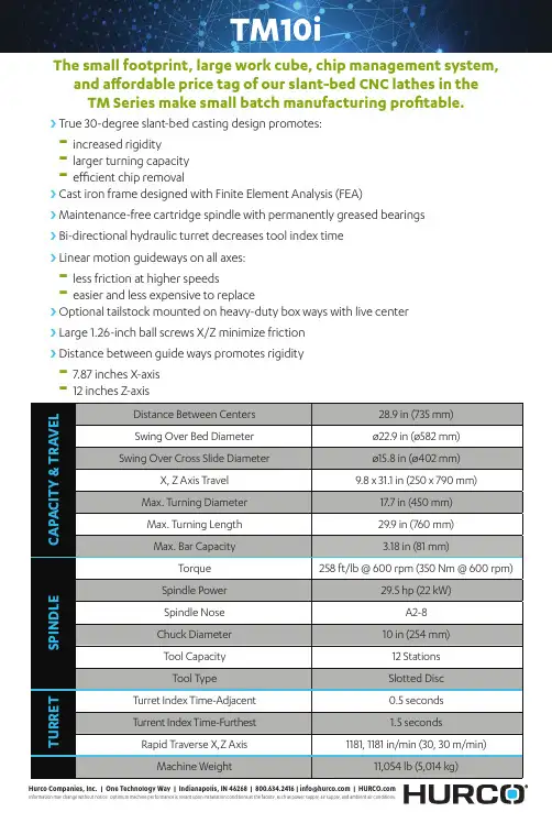
TM10iThe small footprint, large work cube, chip management system, and affordable price tag of our slant-bed CNC lathes in theTM Series make small batch manufacturing profitable.i i True 30-degree slant-bed casting design promotes:-increased rigidity-larger turning capacity-efficient chip removali i Cast iron frame designed with Finite Element Analysis (FEA)i i Maintenance-free cartridge spindle with permanently greased bearingsi i Bi-directional hydraulic turret decreases tool index timei i Linear motion guideways on all axes:-less friction at higher speeds-easier and less expensive to replacei i Optional tailstock mounted on heavy-duty box ways with live centeri i Large 1.26-inch ball screws X/Z minimize frictioni i Distance between guide ways promotes rigidity-7.87 inches X-axis-12 inches Z-axisTMX8MYSii i More Y-axis travel thancompetitive modelsi i Sub-spindle with chiller i i Cast iron frame designed withFinite Element Analysis (FEA)i i True 30-degree slant-bed castingdesign promotes:-increased rigidity-larger turning capacityefficient chip removalThe TMXMY/S mill turn lathes are true slant-bed lathes with all-digital drives and motors and absolute encoders onall linear axes.i i Large ball screws to minimize friction(1.42-inches X/Z/W + 1.26 inches Y)i i Linear motion guideways on all axes:-less friction at higher speeds-easier and less expensive to replace i i Distance between guide wayspromotes rigidity-10 inches X-axis and Y-axis -18.5 inches Z-axis -11.4 inches WVMX6030i-50TOur signature line of VMX machining centers takes machining to the next level. These machines deliver high performance capabilities to any machining application.i i Solid cast iron framei i Generous Y-axis traveli i Wider table extends across the entire Y-axis, which provides the flexibility needed to produce a high mix of partsi i Table moves completely forwardin the work cube for easy operator accessi i Direct coupled ballscrewsi i Larger, heavy-duty roller ways on all three axesi i Ceramic hybrid spindle bearings with lifetime grease i i30-station electric swing-arm ATC (40-station available for 40T spindle) i i2 second tool-to-tool ATC time for 40T spindle (4 seconds for 50T)i i Yaskawa Sigma 5 drivesi i LED lighting shines brighter and saves energyi i MAX5 ergonomically designed console with two 19” LCD screensi i WinMax Mill Conversational and Industry Standard NC programming i iAdjustable height control armVMX60SRTiThe SR series of 5-axis CNC mills offers multiple advantages, starting with the machine's design configuration that utilizes a swivel head with either an A or C style rotary table.i i Direct drive, embedded, C-axis, rotary torque table-Provides additional 3.5 inches inZ-axis to support taller parts-Embedded rotary table designincreases working surface ofmachine table (66 x 26 inches) tosupport secondary operations andor 3-axis work-Unlimited angular movement:reduces cycle time-Stout table: supports heavier partsi i Solid one-piece cast iron frame optimized with both static and dynamic Finite Element Analysis (FEA) i i Yaskawa Sigma V Digital AC Servosi i2 or 4 passage rotary unions for hydraulics and/or airi i Angular encoders for rotary axesi i Pistol-style coolant and air gunsi i WinMax Mill Conversational andNC Programmingi i5-axis/5-sided software features – Tool Path Linearization, Tool Center Point Management, Transform Plane, 3-D Tool Compensation, Tool Vector Input & Retract, Shortest AngularTraversei i Robust control specifications (standard) – 2.7GHz Dual Core Processor, 4GB RAM Memory, 128GBSolid State Hard DriveVMX30UiThe integrated trunnion table design provides more clearance in Z-axis and the ability to machine heavier parts compared to 3-axis mills with trunnion table added.i i Solid one-piece cast iron frame optimized with both static and dynamic Finite Element Analysis (FEA) i i Yaskawa Sigma V Digital AC Servosi i2 or 4 passage rotary unions for hydraulics and/or airi i Electric, side-mounted, 40-Station swing-arm ATCi i Full Enclosure with wide front access doors and fully contained tool storage i i Dual LED work lightsi i Angular encoders for rotary axesi i Pistol-style coolant and air gunsi i WinMax Mill Conversational andNC Programming i i5-axis/5-sided software features – Tool Path Linearization, Tool Center Point Management, Transform Plane, 3-D Tool Compensation, Tool Vector nput & Retract, ShortestAngular Traversei i Ergonomically designed MAX5 console with twin 19” LCD screensi i Robust control specifications (standard) – 2.7GHz Dual Core Processor, 4GB RAM Memory, 128GB Solid State Hard Drivei i Z-axis regenerative brake –no counterbalanceHM1700RiThe Hurco HM1700Ri horizontal mill increases shop productivity with a rotary torque table added to the smart design of the HM1700i. The 8,000 rpm dual winding spindle is equipped for both high and low end torque operations. The large, front and side access doors provide maximum operator efficiency.With fast rapids, large work cube, a smart frame design andUltiMotion technology, complex production parts can bemachined efficiently and accuratelyi i67 x 51 x 35 in (1,700 x 1,300 x 900 mm) travelsi i67 x 36 in (1,700 x 914 mm) table,6,614 lbs (3,000 kg) capacityi i8,000 RPM spindlei i Brushless AC Servosi i WinMax Mill Conversational and Industry Standard NC programming i i Solid cast iron frame i i Heavy duty linear rails for X, Y, & Z-axis i i Double-nut pretensioned ball screws – twin ball screws on X-axisi i Two pallet systemi i LED lighting shines brighter and saves energyi i NEW MAX5 ergonomically designed dual-screen console with19” LCD screensVC500i5-Axis cantilever design supports a wide range of parts. Premium components and Expert Design. Full 110° in both positive and negative direction of the B-axis providessuperb undercutting ability.i i Integrated trunnion table designprovides more clearance in Z-axis and ability to machine heavier parts compared 3-axis mills with trunnion table addedi i Larger, heavy-duty linear guides on allthree axesi i Solid one-piece cast iron frameoptimized with both static anddynamic Finite Element Analysis (FEA)i i Yaskawa Sigma V Digital AC Servos i i 2 or 4 passage rotary unions forhydraulics and/or airi i Full Enclosure with wide front accessdoors and fully contained tool storagei iAngular encoders for rotary axesi i Pistol-style coolant and air guns i i WinMax Mill Conversational andNC Programmingi i 5-axis/5-sided software features – Tool PathLinearization, Tool Center Point Management, Transform Plane, 3-D Tool Compensation, Tool Vector Input & Retract, Shortest Angular Traversei i Ergonomically designed MAX5 console withtwin 19” LCD screensi i Robust control specifications (standard) –2.7GHz Dual Core Processor, 4GB RAM Memory, 128GB Solid State Hard Drivei i Z-axis regenerative brake –no counterbalanceBX60iHigh Speed Double Column Machine. The stability of the double-column, the ladder design of the Z-axis, and the overall weight of the machine (over 44,000 lbs.) provide exceptionalaccuracy and outstanding surface finish capabilities.i i Direct drive ballscrews i i High speed tool changer i i 18,000 RPM high speed spindle i i 47 hp (35 kW) peak spindlei i Integral motorized spindle equipped with ABEC-7 ceramic hybrid bearingsi i HSK 63 toolingi i Extremely rigid and thermally stabledouble-column designi i Generous Y-travel i i Easy access to tablei i Ladder design of bridge providesmaximum support to the head castingi i Close proximity of spindle to bridgecasting reduces overhangi i Brushless AC Servos i i Solid cast iron framei i Large front door opening. Large, hingedside doors i i Larger, heavy-duty roller ways on allthree axesi i 30-station electric swing-arm ATC i i Yaskawa Sigma 5 drivesi i LED lighting shines brighter and saves energy i i MAX5 ergonomically designed console withtwo 19” LCD screensi i WinMax Mill Conversational and IndustryStandard NC programmingHTL8-60iThese box way, gap bed lathes are user friend and makes it easy to load/unload bulky parts. The gap can be removed to accommodate even larger parts close to the headstock. The WinMax control that slidesalong a rail on the front of the machine allows for ease of use.i i Open bed design – easy to load/unload partsi i Gap can be removed to accommodatelarger parts close to the headstocki i Maintenance-free cartridge spindle withpermanently greased bearingsi i Standard tailstock mounted on heavy-duty box ways with live centeri i Hand wheels located below the controlallow manual operation of machinei i Bi-directional hydraulic 8 station turretdecreases tool index time-turret can be positioned anywhere along the saddle-slotted disc-type holds ¾” tool holders-1-¼” boring bar capacity -bi-directional operationi i Max 5 control is mounted on a set of linearrails that travel along the front of the machinei i Designed with both hardened andground ways-X-axis is solid way and Z-axis is box ways -Lined X-axis and Z-axisi i Large ball screws minimize friction -.98 inch X-axis -1.57 inches Z-axisi i Distance between guide ways promotesrigidity-8.4 inches X-axis -14 inches Z-axisVM30iThe VM series of 3-axis machining centers features a small footprint with a large work cube. No other mill packs as much productivity into such an efficiently designed package.i i Solid cast iron frame i i One-piece machine basei i 50 x 20 x 20 in (1,270 x 508 x 508 mm)travelsi i 52 x 20 in (1,321 x 508 mm) table,2,000 lbs (907 kg) capacityi i 10,000 RPM spindle i i 20 hp (15 kW) peak spindle i i CAT 40 tooling i i Brushless AC Servosi i Larger, heavy-duty linear rails on allthree axesi i Mounted to a machined shoulder forincreased rigidityi i Strategically spaced for increasedstrengthi i Wedge locked to a machined shoulder toreduce vibration instead of faster, cheaper face-milled processi i Electric, side-mounted, 20-station,swing-arm ATCi i 2.5 second tool-to-tool ATC timei i Wider table extends across the entire Y-axis,which provides the flexibility needed to produce a high mix of partsi i Table moves completely forward in the workcube for easy operator accessi i Yaskawa Sigma 5 drivesi i LED lighting shines brighter and saves energy i i MAX5 ergonomically designed console with19” LCD screeni i WinMax Mill Conversational and IndustryStandard NC programmingHurcoCompanies,Inc.|OneTechnologyWay|Indianapolis,IN46268|800.634.2416|**************|VM10i PLUSThe Hurco VM CNC vertical milling machines offer powerful machining with a compact footprint, and absolutely the best value on the market. The larger work cube provides impressive X travelwhile not demanding excessive floor space.i i Heavily Ribbed Fine-Grade Cast IronFrame Optimized with Finite Element Analysis (FEA)i i Wedge-locked Heavy duty Linear Rails forAll Three Axesi i Direct Drive Z axis with RegenerativeBrake – No Counterbalancei i Precision Ballscrewsi i Yaskawa Sigma V Digital AC Servos i i Fast 945 ipm Rapid Traverse Rates i i Electric Swing-arm 20 Station ATC –Random Accessi i 2.5 Second Tool-to-Tool ATC Time i i Full Enclosure with Wide Front Access andSide Access Doorsi i LED Work Lighti i Door Safety Interlocks / ANSI B11.23i i Flood Coolant System i i Spindle Thermal Chiller i i Rigid Tapi i Pistol-style Coolant and Air Guns i i Metal Telescopic Way Covers i i Automatic Central Lubrication System i i Power Cabinet Heat Exchanger i i Way Lube Separation System i i Modular One-Piece ITX Control RackHurcoCompanies,Inc.|OneTechnologyWay|Indianapolis,IN46268|800.634.2416|**************|VMX42DiThe Hurco VMX42Di CNC vertical milling machine is the industryworkhorse. These CNC machining centers are the perfectcombination of performance and flexibility.i i Heavily Ribbed Fine-Grade Cast IronFrame Optimized with Finite Element Analysis (FEA)i i Wedge-locked Heavy duty Linear Railswith roller bearings on X/Y/Z axesi i Direct Drive Servos on X/Y/Z Axes i i Double-Nut Pre-Tensioned BallscrewsAnchored at Both Endsi i New Max 5 control height adjustmentcapabilityi i Yaskawa Sigma V Digital AC Servos i i Fast 1,496 ipm Rapid Traverse Rates (X,Y)1,260 ipm on Zi i Full Enclosure with Wide Front Access andSwing-open Side Doorsi i Right and Left Side LED Work Lights i i 3-stack Signal Light i i Door Safety Interlocks i i Spindle Thermal Chiller Assembly i i Flood Coolant Ring and Washdown System i i Pistol-style Coolant and Air Guns i i Metal Telescopic Way Covers i i Lift-Up Chip Conveyori i Automatic Central Lubrication System i i Power Cabinet Heat Exchanger i i Way Lube Separation System i i Modular One-Piece ITX Control Rack。


Lift Products Inc.W226 N900 Eastmound Dr. Waukesha, WI 53186 Telephone: (262) 521-5720 Fax: (262) 521-5725Parts & Service: 877-543-8776MOTO CART PRODUCT SERVICE INFORMATIONINTRODUCTION (2)SAFETY FIRST (3)OPERATING THE MOTO CART (4)MODEL MC-10-S / MC-10-M /MC-10-L /MC2-HD20 /MC2-HD15 (EZ-GRIP CONTROLS) (4)ON-OFF KEY SWITCH (4)FORWARD/REVERSE (4)SPEED MODES (4)EMERGENCY STOPPING (4)BATTERY CONDITION (4)RUNNING (5)BRAKING SYSTEMS (5)CHARGING (6)BATTERIES (6)BATTERY LIFE (6)BATTERY LOAD TESTING (7)CIRCUIT BREAKER (7)MAINTENANCE (7)MAINTENANCE SCHEDULE (7)MAINTENANCE PROCEDURES (8)DIAGNOSTICS & TROUBLESHOOTING (9)PUSHING MANUALLY (11)SPECIFICATIONS (12)Welcome to the MOTO CART . . . a member of the Lift Products family of quality mobility products. We know you’ll be depending on it, so we have taken great care to make it completely reliable. This owner’s manual is designed to help you get the most out of your CART and includes very important safety and care information. Please read it thoroughly and keep it handy for reference. Thank you for choosing the MOTO CARTInformation in this manual is based upon specifications in effect at the time of publication. Lift Products reserves the right to make changes at any time without notice.Be sure to complete the Product Service Information box on the inside front cover. This will be your record of important information, which will help you if your MOTO CART ever requires service. When seeking repair parts while your MOTO CART is under warranty, a copy of your bill of sale may be requested to verify warranty status.FAILURE TO READ THIS OWNER’S MANUALWILL VOID THE WARRANTYIf there is anything in this manual that you do not completely understand or are unsure of,DO NOT OPERATE your MOT CART. Call Customer Service at:1-877-543-87762To prevent accidents which can cause injury to you, damage the MOTO CART or damage your cargo, observe the following rules:READ THE OWNERS'S MANUAL BEFORE OPERATING THE MOTO CART.1. Read and understand this owner’s/operator’s manual before operating the MOTO CART2. Read and understand all safety instructions provided with the MOTO CART.3. Only trained personnel should be allowed to use the MOTO CART. All persons using the CART must read this owner’s/operator’s manual.4. The MOTO CART has a maximum load capacity of 1500 pounds. Do not exceed the rated capacity for your model.MC2-HD20 2000MC2-HD15 1500MC-10-L 1500MC-10-M 1500MC-10-S 15005. Do not travel up or down inclines greater than 6°.6. Always turn the key switch off before loading or unloading the CART.7. Always take corners slowly and with caution to prevent the load from shifting.8. Do not travel sideways across inclines.9. Do not stop the MOTO CART on an incline. Always park, load and unload on a flat, level surface.10. Do not go up and down curbs. Only operate theCART on smooth surfaces.11. Always unplug the batteries before making anyadjustments or repairs to the MOTO CART. 12. Always load the CART evenly, distributingthe load to prevent tipping.13. Do not defeat any safety equipment on theCART.14. Do not use the MOTO CART to push or pullobjects or other carts.15. Do not operate the MOTO CART in wetenvironments.16. Do not expose the MOTO CART to hightemperatures. The CART is battery operated. Batteries may be severely damaged if exposed to high temperatures.17. Do not operate the MOTO CART with abroken wheel or broken or bent caster.18. Use extreme caution when operating theMOTO CART near doorways, in hallways and near stairwells. Reduce speeds in these areas.19. Do not manually release theelectromechanical brake on or near an incline. If you must release this brake, release the brake only when on a level surface and with the CART completely unloaded. Instructions for releasing the brake are in the section titled "Pushing Manually".20. Test the operation of the MOTO CART inan environment with sensitive electronic equipment prior to the use in that environment. The CART has not been tested with all manufacturers equipment and may react to, or cause a reaction in the electronic equipment.3We would like you to get the most out of your MOTO CART. When you use the CART for the first time, you must know how to properly operate and care for it to avoid unsafe situations. Please read this manual thoroughly and become familiar with all of the safety information provided.Be aware of your surroundings – drive slowly and cautiously. Avoid collisions which could cause damage to the CART or shift the load, damaging the goods, or injuring you or surrounding people.Anticipate and avoid unsafe situations. Be courteous of others and let your presence be known.Perform first time operation in an open area on a flat surface free of obstacles. Have someone familiar with the operation of the MOTO CART available to assist you.First time operators should read and understand all instructions and controls before attempting to operate the CART.On-Off Key SwitchThe on-off key switch is located on the side of the Roller Grip control unit. To turn the power on, fully insert the key into the key switch and turn the key clockwise. When the power is on, the status LED located on the top of the control unit will illuminate.Forward/ReverseThe Forward/Reverse direction of the Cart is controlled by the thumb-wheels located on either side of the Roller Grip control unit. Pushing either of the thumb-wheels forward (clockwise) will move the Cart forward. Pushing either of the thumb-wheels backward (counterclockwise) will move the Cart in reverse.Speed ModesThe Roller Grip control provides two speed modes, “Rabbit” (fast) or “Turtle” (slow). A “Rabbit/Turtle” rocker switch located on top of the unit allows selection of the desired speed mode. Depressing the back of the rocker switch (Turtle icon) selects the slow mode, while depressing the front of the switch (Rabbit icon) selects the fast mode.Always select the Turtle/Slow speed during training, in close quarters, or in circumstances in which you risk damage or injury if the Rabbit (fast) speed is selected.Emergency StoppingTo stop the Model MC-10M /MC-10-L/ MC-10-S/ MC2-HD15 /MC2-HD20 CART in an emergency, press in on the Emergency Stop Button. The Emergency Stop Button is the large red button covering most of the Roller-Grip control unit’s front. To restart the Cart, the key switch must be cycled (turned off and then back on).Battery ConditionThe Battery Gauge located on top of the Roller-Grip control unit indicates when the Cart’s batteries need to be recharged. If the Battery Gauge shows red, yellow and green, the batteries are charged. If the Battery Gauge shows just red and yellow, the batteries need to be charged as soon as possible. If the Battery Gauge shows just red (either steady or flashing slowly), the batteries need to be charged immediately. The Battery Gauge reading is more accurate after the power has been on for at least one4RunningThe Model MC-10-M/MC-10-L/MC-10-S/MC2HD-15/MC2-HD20 Cart is equipped with the ergonomically designed Roller-Grip control unit. To operate the Cart, follow the steps below:1. Turn the key switch clockwise to the Drive position. Select the desired speed mode using the “Rabbit/Turtle” switch2.Gently push either of the Roller-Grip thumb-wheels forward (clockwise). The CART will start to move and accelerate forward, away from you.3. To stop, release the control lever. The MOTO CART will gently slow down with the aid of dynamic regenerative braking.4. To go in reverse, gently push either of the Roller-Grip thumb-wheels backward (counter- clockwise). The CART will start to move and accelerate toward you. For safety, the maximum speed in reverse is normally set slower than the forward speed.Braking SystemsAll MOTO CARTS have two types of braking systems, dynamic regenerative braking and electro-mechanical braking.1. Dynamic Regenerative Braking - Dynamic regenerative braking automatically brings the CART to a smooth stop when the thumb-wheel is released. However, it does not lock the wheels in place.2. Electromechanical Braking - After the dynamic braking has brought the CART to a stop, the electromechanical brake will lock the drive wheels in place. The electromechanical brake is a parking brake and can be applied instantly by pressing the emergency stop switch (located on the front of the Model MC-10-M/MC-10-L/MC-10-S/MC2HD-15/MC2-HD20 Roller-Grip control unit). The center, or drive wheels, must be contacting the floor surface for the brake to hold.ChargingThe MOTO CART is equipped with two U-1 Absorbed Glass Mat (AGM) batteries, which require charging on a regular basis. An on-board charging system is integrated into the electronics of the CART to make charging easy.1. Position the MOTO CART close to an AC poweroutlet. The CART can be charged using any voltage between 100 and 240 volts AC 50/60 Hz.Model MC-10-M/MC-10-L/MC-10-S/MC2HD-15/MC2-HD20 is equipped with an on-board coil cord for charging (if required, use a plug adapter from the country in which the CART will be used).2. Turn the unit off and remove the key.3. Find the coil cord located just below the frame onthe control handle end of the CART.4. Plug the coil-cord directly into the power supplyoutlet. If needed, connect only an industrial grade grounded extension cord to the coil-cord and then to the AC power supply outlet. Make sure the plug is fully engaged into the supply outlet.5. Allow the unit to charge overnight – six to eighthours for a full charge. For optimum battery life, charge the CART whenever it is not in use – it cannot be over-charged.6. With the power on, the Battery Gauge shows thecharging status. If the Battery Gauge shows red, yellow and green, the batteries are nearly or fully charged. If the Battery Gauge shows red and yellow, or just red, charging needs to be continued.7. Unplug the cord from the power supply outlet(and if used, the extension cord from the unit) before attempting to turn the unit on.56Circuit BreakerA manually reset circuit breaker is located on one battery attached to the positive (+) terminal. The circuit breaker protects the wiring and batteries against damage in the event of a short circuit. If a breaker opens, reset it by pushing the tab down. If it opens again in a short time, there is a short circuit, which must be found and corrected.If any additional wiring is added to the CART, it must not bypass the break er.DO NOT DEFEAT THE BREAKER! DO NOT REMOVE OR BYPASS THE CIRCUIT BREAKER!DO NOT TAPE THE TAB DOWN!MAINTENANCE SCHEDULEYour MOTO CART will give you years of safeand dependable service in return for regularmaintenance and early attention to anydeveloping problems. We recommend thefollowing maintenance program.If you use your CART often, you may find it to your advantage to perform this maintenance more frequently.CAUTION: Disconnect the batteries beforePerforming any maintenance.Every Day or as Needed:1. Maintain the batteries’ charge.2. Clean debris from the wheels and drive unitassembly.Once Each Month:1. Check for loose connectors and any signs ofunusual wear.2. Grease caster wheel swivel assemblies. Use only industrial grade grease in the caster wheel swivel assemblies.Once Every Three Months:1. Clean your CART with a damp sponge.2. Check the wires for wear, fraying or cracking.3. Check the connectors for wear or cracking.4. Examine the tires and wheel assemblies for wear ordamage.NOTE: THIS MAINTENANCE IS BEST PERFORMED BY YOUR LOCAL AUTHORIZEDSERVICE CENTER.Cleaning Your MOTO CART:Turn the power OFF and disconnect the batteries before cleaning your CART. Use warm soapy water and a damp sponge to clean your MOTO CART. DO NOT pressure-wash or hose your CART off. Excessive water may damage electronic components.Do not use harsh or abrasive cleansers on the MOTO CART or its tires. These types of cleansers will damage the finish of your CART, and may cause premature tire wear. Clean your tires with a bristle brush dipped in warm water.7MAINTENANCE PROCEDURESLubrication:All wheel bearings are sealed and permanently lubricated. Spray silicone lubricants (or WD-40*) may be used on any other moving parts. Apply this lubricant whenever there is “stickiness” in the moving parts. *WD-40 is a registered trademark of the WD-40 Company and is Not affiliated with Electro Kinetic Technologies, LLC.Replacing the Batteries:Make sure that the brake is applied (brake handle down). Turn the power OFF and disconnect the batteries.Cut the wire ties holding the main cable and the charger cable to the drive system frame and disconnect the cables.Remove any load from cart. You may want a second person to help with dropping the drive system. Remove the hitch pin clips from the hitch pins and remove the hitch pins from the U brackets that attach the drive system to the cart.Some downward pressure on the platform maymake the pins easier to remove. The drivesystem frame should then drop away from the cart frame. Use caution, as the drive system is heavy.Raise the front of the cart and remove the twosuspension springs.Release the brake and roll the drive system out from under the cart.Undo the battery hold down straps and remove the batteries from the battery tray. Remove the circuit breaker and wires from the old batteries. Install the new batteries by following these steps inreverse order. Remember to re-apply the brake (push brake handle down).WARNING: Do not touch both the negativeand positive terminals of the batteries with a conductive material (e.g., metal) or sparks, burns, or explosion may result.8Your MOTO CART has been designed and built to be dependable and trouble free, but we know that there can be unexpected problems with any technical product. The following checklists will give you a “First Aid” approach to dealing with most problems. You can also call our Service Hotline: 877-543-8776.SYMPTOM POSSIBLE CAUSESOLUTION Key Switch turned to Off position.Turn Key Switch to Drive (right) position. Emergency Stop Switch has beenpressed.Recycle Key switch. Circuit breaker open.Reset circuit breaker. Unit Dead, BCI DarkPower connection interrupted.Check power cables to batteries. Obstruction in pathway of wheels. Check for obstruction. Unit Dead, BCIIlluminated Motor worn out.Contact Authorized Service Center. Battery charge low.Charge batteries. Unit Runs SlowWorn batteries.Charge batteries. Load test batteries. Charger power interrupted.Check wall outlet for continuous power. Loose connection in wiring.Check all exposed wire connections. Battery Weak orWon’t Take aCharge Charger burned out.Replace charger. Loose connection in wiring. Check all exposed wire connections. IntermittentRunning Worn motor brushes. Contact Authorized Service Center. Casters require lubrication. Lubricate casters.Hard to TurnWorn out caster bearings. Replace casters.9Moto Cart Model MC-10-M / MC-10-L / MC-10-S / MC2HD-15 & MC2-HD20 Carts equipped with Roller-Grip Hand Controls provide diagnostics information to assist technicians in troubleshooting drive system problems. The diagnostics information is obtained by observing the fault codes issued by the status LED located on the Roller-Grip control unit.During normal operation, with no faults present, the status LED is steadily on. If the controller detects a fault, the status LED displays a fault identification code. The number of flashes indicates the nature of the fault. The codes are listed in Table 1 below, along with possible causes of the fault indicated.Table 1 DIAGNOSTIC CODESNUMBER OFFLASHESPOSSIBLE CAUSE1 The battery needs charging or there is a bad connection to the battery. Check the connections to the battery. If the connections are good, try charging the battery.2 There is a bad connection to the motor. Check all connectionsbetween the motor and the control system.3 The motor has a short circuit to a battery connection. Contact yourservice agent.4 Not used.5 Not used.6 The controller is being inhibited from driving. This may be because theEmergency Stop Button was pressed. Turn the Key switch Off and On.7 A throttle fault is indicated. Make sure that the throttle is in the restposition before switching on the CART.8 A controller fault is indicated. Make sure that all connections aresecure. Contact your service agent.9 There is a bad connection to the parking brake. Check all connectionsbetween the parking brake and the controller.10 An excessive voltage has been applied to the controller. This is usually caused by a poor battery connection. Check the battery connections.RipplingUp & Down Throttle applied at power up. Release throttle lever.10PUSHING MANUALLYThe drive system on the MOTO CART can be disabled to allow you to push the unit Manually. To disable the drive system:1. On a level surface only, lift up on the brake handle located under the deck near the drive wheels to disable the Electromechanical Parking Brake.2. Turn the Key Switch to the Off position to disable the Dynamic Braking.AFTER PUSHING, RETURN THE BRAKE LEVER TO THE DOWN POSITIONTO PREVENT THE CART FROM ROLLING AND TO ENABLE DRIVING.WARNING:DO NOT RELEASE THE BRAKE ON OR NEAR AN INCLINED SURFACE.THE UNIT WILL NOT STOP ON ITS OWN WHEN THE BRAKING SYSTEM IS DISABLED.SEVERE INJURY MAY RESULT IF THE UNIT IS LEFT TO ROLL UNATTENDED. Array11• Spring-suspension and center wheeltransaxle drive system• Speed range, 0-3 MPH (0-4.8 km/hr)• Maintenance free permanent magnet motor • Non-marking tires• Variable speed control• Horn, key switch, emergency stop• Hi/Low speed switch• (2) 33AH, 12 volt, AGM maintenance free batteries• On board 100-240, 50/60 Hz, UL listed battery charger• Automatic dynamic braking & parking brake • Deck Height: 11.5” (290 mm)• Incline Rating: 6°Model MC-10-MUsable Platform Length: 48”Usable Platform Width: 24”Capacity: 1,500 lbs.Model MC-10-LUsable Platform Length: 60”Usable Platform Length: 24”Capacity: 1500 lbsModel MC-10-SUsable Platform Length: 41 ½”Usable Platform Width: 24”Capacity: 1500 lbsModel MC2-HD15Usable Platform Length: 48”Usable Platform Width: 36”Capacity: 1500 lbsModel: MC2-HD20Useable Platform Length: 48”Useable Platform Width: 36”Capacity: 2,000 lbs.1213Lift Products, Inc.W226 N900 Eastmound Dr. Waukesha, WI 53186 Telephone: (262) 521-5720 Fax: (262) 521-5725Parts & Service: 877-543-8776。

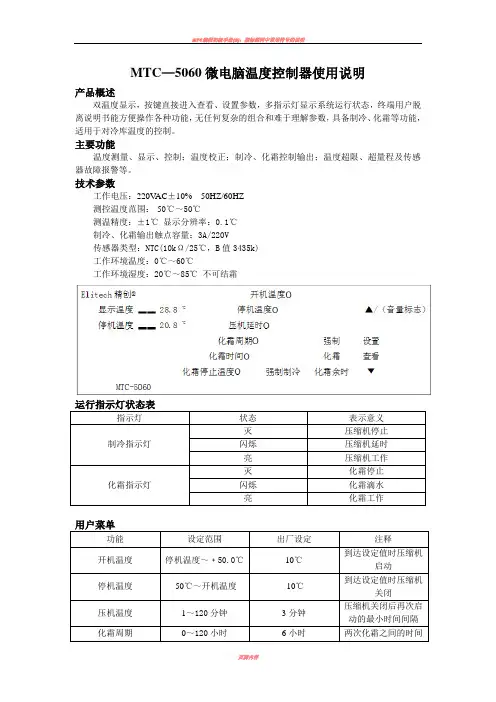
MTC—5060微电脑温度控制器使用说明产品概述双温度显示,按键直接进入查看、设置参数,多指示灯显示系统运行状态,终端用户脱离说明书能方便操作各种功能,无任何复杂的组合和难于理解参数,具备制冷、化霜等功能,适用于对冷库温度的控制。
主要功能温度测量、显示、控制;温度校正;制冷、化霜控制输出;温度超限、超量程及传感器故障报警等。
技术参数工作电压:220V AC±10% 50HZ/60HZ测控温度范围:-50℃~50℃测温精度:±1℃显示分辨率:0.1℃制冷、化霜输出触点容量:3A/220V传感器类型:NTC(10kΩ/25℃,B值3435k)工作环境温度:0℃~60℃工作环境湿度:20℃~85℃不可结霜指示灯状态表示意义制冷指示灯灭压缩机停止闪烁压缩机延时亮压缩机工作化霜指示灯灭化霜停止闪烁化霜滴水亮化霜工作功能设定范围出厂设定注释开机温度停机温度~﹢50.0℃10℃到达设定值时压缩机启动停机温度-50℃~开机温度-10℃到达设定值时压缩机关闭压机温度1~120分钟3分钟压缩机关闭后再次启动的最小时间间隔化霜周期0~120小时6小时两次化霜之间的时间9 菜单操作9.1 用户菜单设置:在运行状态下,按住“设置/查看”键持续5秒以上至“显示温度”显示窗显示“SET”时,则表明进入用户菜单设置,“开机温度”指示灯亮,以后每按下并立即松开“设置/查看”键一次,则进入下一项参数设置(可循环操作),相应的参数指示灯亮。
进入用户菜单后,按“▲/(音量标志)”或“▼”键可修改“停机温度”显示窗里德设定参数。
9.2 系统菜单设置:9.2.1 在运行状态下,同时按住“设置/查看”与“▼”键持续5秒以上至“显示温度”显示窗显示“F1”时,则表明进入系统菜单设置,以后每按下并立即松开“设置/查看”键一次,则进入下一项参数设置(可循环操作)。
进入系统菜单后,按“▲/(音量标志)或“▼”键可修改“停机温度”显示窗里的设定参数。

Hi-Pro@交通数据采集专家多功能交通调查仪操作手册MTC-102008.9北京奥泽尔科技发展有限公司BEIJING AOZER TECH & DEVELOPMENT CO.,LTDMTC-10快速启动指南1. 打开MTC-10,系统进行自检,显示当前存储情况。
待系统完全启动以后,屏幕上将显示主菜单。
将光标移到“Count”选项上时,按“Ent”键。
2. 在接下来的界面中, 开始一个新的调查,按“Tab”键直到光标移到“New Count”选项上,然后按“Ent”键。
3. 然后给出了六种调查类型。
使用以下简称:HVC=路段24种车型调查(Highway Vehicle Classification ) ITF=单方向路口6种车型转向调查(Intersection Turning Flow ) VLP=车辆区间旅行时间车牌照记录(Vehicle License Plate ) TTD=单车旅行时间及延误调查(Travel Time and Delay ) MLH=多车道车头时距或间距调查(Multi-Lane Headway ) RTS=24个键原始时间标记录(Raw Time Stamped )按TAB 键,直到光标移到你所要调查的选项上,然后按一下Ent 键。
RTS 原始时间标调查可用特殊调查需求的多种类型的数据采集,适合于二次开发。
4. MTC-10所能做的每一项调查的参数设置和数据采集都有其具体的步骤。
对于如何进行每项调查的更多信息,请参考本手册后面相关章节。
5. 当您完成了调查,按”Bak”键退出当前调查,然后关闭MTC-10电源,设备中即已保存了您的调查数据。
注意:完成调查后,一定要先按”Bak”键退出当前调查,然后再关闭电源,这样可以确保数据万无一失!…AOZER TECH… Hi-Pro MTC20 Traffic-Data Counter All Rights Reserved…STATUS… Counts Stored: 001 Memory Used: 001%Battery Left: 7.4VView Count Clear Setup Unload View memory, battery left and date, time.View Count Clear Setup Unload Start or continue a count.HVC ITF VLP TTD MLH RTS Exit Highway Vehicle Classification countNew CountContinue ExitStart a new count第1章MTC-10 简介Hi-Pro MTC-10手持式多功能交通调查仪是什么?MTC-10是一种手持式电子交通调查设备,能使您进行某些最普通的交通数据采集工作。
MTC-CBT-70T Bolt-On TransformerModule for CBT 70 ModelsProfessional SeriesKey Features:᭤Adapts the CBT 70J-1 (and 70JE-1)for Use on Distributed SpeakerLines᭤120W, 60W, 30W for 70V or 100V(plus 15W for 70V)᭤Bolts onto Back of CBT 70J-1 or70JE-1 Speaker᭤Gland Nuts Provide Water TightSealApplications:MTC-CBT-70T is a bolt-ontransformer module to adaptCBT70J-1 and CBT 70JE-1 (andCBT70J-1/JE-1 arrays) for use ondistributed loudspeaker lines. It allows long cable runs and multiple speakers to be driven from a single distributed system amplifier channel. Transformer taps include 120W,60W, and 30W for 70V and 100V distributed lines, plus 15W for 70V only.Connections are made via customer-supplied cable to screw-down terminals inside the enclosure. Two gland nuts are provided –one for the cable into the enclosure from the amplifier and one for the cable from the enclosed terminal strip tothe input terminal of the loudspeaker. The gland nuts form a water-tightseal when used with round jacketed cable with outside diameter between 4.0 mm (0.16 in) and 9.0 mm(0.36in).The tap selection is made via the terminal connection of the cable from the power amplifier to the appropriate terminals on the internal terminal strip.Mounting holes are provided thatfit via two 6 mm screws to any of the two side-by-side insert points on the back of the CBT 70J-1 or CBT 70JE-1 cabinet.Note that MTC-CBT-70T extends86mm (3.4 in) from the back of the CBT cabinet.Available in black or white (-WH).Specifications:Transformer Taps:120W, 60W, 30W (and 15W at 70V only)Connection:CE-compliant barrier strip terminals. Terminals accept up to8mm outside 4 mm inside open-lug (#6 or #8) plus bare wireup to 2.5 mm2(12 AWG).TERMINALS:Terminal 1 = Common (black wire from transformer)Terminal 2 = 120W @ 70V, N/C @ 100V (orange wire from transformer)Terminal 3 = 60W @ 70V, 120W@100V (purple wire from transformer)Terminal 4 = 30W @ 70V, 60W @ 100V (blue wire from transformer)Terminal 5 = 15W @ 70V, 30W @ 100V (white wire from transformer)Terminal 6 = N/C (no wire from transformer)Terminal 7 = + Output to loudspeaker + terminal (yellow wire fromtransformer)Terminal 8 = –Output to loudspeaker - terminal (green wire fromtransformer)Maximum Insertion Loss= Less than 1 dB at any tap.Gland Nuts:Two total. One gland nut by the transformer selectionterminals for cable from amplifier and one gland nut by thetransformer secondary terminals (green and yellow wires) foroutput to speaker terminals. It is recommended to orient glandnuts toward bottom of enclosure.Watertight seal requiresround jacketed cable with outside diameter between 4.0 mm(0.16 in) and 9.0 mm (0.36in).Mounting to Speaker Cabinet:Two holes in the back of the enclosure 70 mm (2.75 in) apart.Insert included 6 mm screw from inside MTC-CBT-70Tenclosure, using 1 flat washer and 1 lock washer, into theside-by-side M6 insert points on the back of the CBT70J-1 orCBT70JE-1 cabinet.Enclosure Material:Fiberglass filled ABS.Environmental Capability:IP-55 rated, per IEC529. UV, moisture and salt-spray resistant.Agency Rating:Transformer UL registered per UL1876, Isolating Signal andFeedback Transformers for Use in Electronic Equipment.Dimensions (H x W x D):157 x 114 x 86 mm (6.2 x 4.5 x 3.4 in) including gland nuts.128 mm (5.0 in) enclosure height for enclosure only.Net Weight: 1.13 kgs (2.5 lbs)Shipping Weight: 1.36 kgs (3.0 lbs)Included Accessories:Two 6 mm (x 15mm length x 1.0 thread pitch) bolts, flatwashers & lock washersJBL continually engages in research related to product improvement. Some materials, production methods and designrefinements are introduced into existing products without notice as a routine expression of that philosophy. For this reason, any current JBL product may differ in some respect from its published description, but will always equal or exceed the original design specifications unless otherwise stated.Cable not included.SS MTC-CBT-70T CRP 01/13᭤MTC-CBT-70T Bolt-On Transformer Module for CBT 70 Models DimensionsJBL Professional8500 Balboa Boulevard, P.O. Box 2200Northridge, California 91329 U.S.A.© Copyright 2013 JBL ProfessionalWiring DiagramMounting onto SpeakerShown mounted to top insert points of CBT 70J-1.。
CT10蓝牙条码枪说明书使用需知安全注意事项请勿擅自随意拆装机器,或是将异物置入机器造成短路或电路损坏。
请勿使机器、电池接近火源。
维护注意事项机器外壳可以干净的湿布擦拭。
若长时间不用本产品,请将机器与电池分开包装后储存。
若发现机器故障,请记下发生状况后与维修人员联系。
目录使用需知 (2)安全注意事项 (2)维护注意事项 (2)目录 (3)认识CT10条码扫描枪 (5)产品特色 (5)外观说明 (5)按键说明 (6)技术参数 (6)正确扫描方式 (7)错误的扫描方式 (7)快速开始 (8)进入设定模式 (9)退出并保存设定模式 (9)退出不保存设定模式 (9)恢复出厂设置 (9)查看软件版本号 (10)保存自定义设置 (11)Chapter 1.产品特性与基本设定 (12)1.1电池 (13)1.1.1电池安装(充电) (13)1.1.2如何操作CT10蓝牙扫描枪 (13)1.1.3自动关机 (14)1.2传送缓冲区 (15)1.2.1盘点功能 (16)1.3LED指示灯 (17)1.4蜂鸣器 (18)1.4.1音量控制 (19)1.5扫描模式 (20)1.5.1手动识读模式 (20)1.5.2连续扫描模式 (21)1.5.3自动关闭模式 (22)1.5.4自动感应模式 (24)1.6支持的条码类型 (25)1.7 USB有线数据传输 (25)Charpter 2 如何连接蓝牙 (27)2.1.蓝牙传输界面的设定 (29)2.1.1蓝牙SPP (29)2.1.2蓝牙HID (29)2.2蓝牙连线设定 (30)2.3通过蓝牙连线到电脑 (31)2.4通过蓝牙连接到PDA (34)2.4.1一键Android设备连接 (38)2.4.2一键iOS设备连接 (40)2.4.3蓝牙输入法连接 (42)Chapter 3 条码的设定 (50)3.1 CODABAR (51)3.2 CODE 25 –INDUSTRIAL25 (52)3.3 CODE 25 –INTERLEA VED 25 (54)3.4 CODE 25 –MA TRIX 25 (55)3.5 CODE 25-STANDARD 25 (56)3.6 CODE 39 (57)3.6.1 开启或关闭Code 39 (57)3.6.2 传送START/STOP字元 (57)3.6.3 校验 (58)3.6.4 ASCII码识别范围设置 (58)3.7CODE 93 (59)3.8 Code 128 (60)3.9 EAN-8 (61)3.9.1开启或关闭EAN-8 (61)3.9.2转换成EAN-13 (61)3.9.3传送checksum (62)3.10 EAN-13 (63)3.10.1开启或关闭EAN-13 (63)3.10.2转换成ISBN (63)3.10.3传送checksum (64)3.11 UPC-A (65)3.11.1 UPC-A输出0 (65)3.11.2 UPC-A传送checksum (65)3.12 UPC-E (66)3.12.1开启或关闭UPC-E (66)3.12.2 UPC-E传送checksum (66)3.13 MSI (67)3.14 CODE 11 (68)Chapter 4 资料传输格式 (69)4.1条码类型代码(CODE ID) (70)4.2条码末端字符设定 (71)附录一 (72)认识CT10条码扫描枪产品特色四种扫描模式,包括连续扫描模式、手动识读模式、自动关闭模式、自动感应模式支持常用条码通过LED灯、蜂鸣器提供反馈机制成功读取条码的音量大小可通过设定条码来改变内置256Kb存储器提供离线缓存使用,可储存大约2600条资料支持蓝牙SPP支持蓝牙HID可通过读取设定条码来改变资料传输格式、资料编辑设定、条码类型设定★丰富的解码种类★全身防震防摔设计★全部自主知识产权★极其舒适的操作手感★按键寿命高达300万次★支持蓝牙标准协议无需适配器★ 1500MAH大容量锂离子电池★大容量锂电池超长的工作时间外观说明按键说明注:长按扫描键3s开机,长按扫描键3s关机。