XR10CX-dixell小精灵说明书
- 格式:pdf
- 大小:845.48 KB
- 文档页数:4

Dell EMC PowerEdge XR11 和 XR12技术指南12 2021注意、小心和警告:“注意”表示帮助您更好地使用该产品的重要信息。
:“小心”表示可能会损坏硬件或导致数据丢失,并告诉您如何避免此类问题。
:“警告”表示可能会导致财产损失、人身伤害甚至死亡。
© 2021 年 Dell Inc. 或其子公司。
保留所有权利。
Dell、EMC 和其他商标是 Dell Inc. 或其附属机构的商标。
其他商标可能是其各自所有者的商标。
章 1: 系统概览 (6)关键工作负载 (6)新技术 (6)章 2: 系统功能部件 (8)章 3: 机箱视图和功能部件 (10)机箱视图 (10)XR11 正面拆装机箱的前视图 (10)XR11 背面拆装机箱的前视图 (11)XR12 正面拆装机箱的前视图 (12)XR12 背面拆装机箱的前视图 (13)XR11 正面拆装机箱的后视图 (14)XR11 背面拆装机箱的后视图 (14)XR12 正面拆装机箱的后视图 (15)XR12 背面拆装机箱的后视图 (15)XR11 正面拆装机箱内部 (16)XR11 背面拆装机箱内部 (18)XR12 正面拆装机箱内部 (20)XR12 背面拆装机箱内部 (22)快速资源定位符 (QRL) (23)章 4: 处理器 (25)处理器特性 (25)XR11 和 XR12 支持的处理器 (25)章 5: 内存子系统 (27)支持的内存 (27)章 6: 存储 (29)支持的驱动器 (29)XR11 的内部存储配置列表 (30)XR12 的内部存储配置列表 (30)外部存储器 (32)章 7: 扩展卡和扩展卡转接卡 (33)PowerEdge XR11 系统的扩展卡和提升板 (33)扩展卡安装原则 (33)PowerEdge XR12 系统的扩展卡和提升板 (37)扩展卡安装原则 (38)章 8: 功率、散热和声音 (45)XR11 和 XR12 的电源 (45)针对 XR11 和 XR12 的散热 (46)目录3散热设计 (46)声音 (47)XR11 和 XR12 的声音设计 (47)章 9: 机架、导轨和线缆管理 (52)导轨信息 (52)2 柱机架中的滑动导轨 (53)四柱机架中的滑动导轨 (54)Pelican 包装箱中的滑动导轨 (56)线缆固定臂 (56)防变形条 (57)章 10: 支持的操作系统 (59)章 11: Dell EMC OpenManage 系统管理 (60)服务器和机箱管理器 (60)Dell EMC 控制台 (61)自动化启用程序 (61)集成第三方控制台 (61)连接第三方控制台的接口 (61)Dell EMC 更新公用程序 (61)戴尔资源 (61)章 12: Dell Technologies 服务 (63)Dell EMC ProDeploy Enterprise Suite (63)Dell EMC ProDeploy Plus (64)Dell EMC ProDeploy (64)基本部署 (64)Dell EMC 服务器配置服务 (64)Dell EMC 派驻服务 (64)Dell EMC 远程咨询服务 (64)Dell EMC 数据迁移服务 (64)Dell EMC ProSupport Enterprise Suite (64)面向企业的 Dell EMC ProSupport Plus (65)面向企业的 Dell EMC ProSupport (65)Dell EMC ProSupport One for Data Center (66)ProSupport for HPC (66)支持技术 (67)Dell Technologies Education Services (68)Dell Technologies 咨询服务 (68)Dell EMC 托管服务 (68)章 13: 附录 A.其他规格 (69)机箱尺寸 (69)机箱重量 (71)视频规格 (71)USB 端口 (72)XR11 的 USB 端口规格 (72)XR12 的 USB 端口规格 (72)4目录适用于 XR11 和 XR12 的电源装置 (73)XR11 和 XR12 的电源效率 (75)环境规格 (75)XR11 和 XR12 的 ASHRAE A3/A4/加固支持限制 (76)微粒和气体污染规格 (78)加固认证和规格 (79)章 14: 附录 B.标准遵从性 (80)章 15: 附录 C 其他资源 (81)目录51系统概览Dell™ PowerEdge™ XR11 和 XR12 是戴尔最新的加固服务器,旨在使用高度可扩展的内存、I/O 和网络选项来运行复杂的工作负载,这些位置受空间或环境挑战的限制。

Congratulations on your purchase of a Fender ®Stage 100/100H/160 amplifier. With worldclass Fender quality built-in, Stage 100/100H/160amplifiers deliver the tone and features that today’s musicians demand:•Two channels with independent tone controls.•Switchable “More Drive” pre-amp boost for harmonically rich leads.•160 watts of output power @ 4 ohms (100 watts @ 8 ohms).•Rear panel Effects Loop jacks for connection to external effects devices or “add-on” ampli-fiers.•Balanced 3-pin XLR line out jack for connec-tion to re c o r ding or sound-re i n f o r c e m e n t equipment.•Classic Fender spring Reverb effect.•Footswitch jack with channel and pre-amp switching capabilities.The operation and functions of all three versions (Stage 100 and Stage 160 “amplifier/speaker combinations” and the Stage 100H “amplifier head only”) are identical except for the speaker output functions (see items 3-5 under Rear Panel Functions).1.INPUT 1 - Plug in your guitar at this jack.2.INPUT 2 - A lower impedance / sensitivity input for guitars with active pickups. Both inputs are identical if used simultaneously.•NOTE: The N o r mal channel must be selected for items 3-7 to function. See CHANNEL SELECT (item 10).3.VOLUME (Normal Channel) - Adjusts the loudness of the of the amplifier while in the Normal channel.4.TREBLE - Adjusts the high-frequency level of the Normal channel.5.MID - Adjusts the mid-frequency level of the Normal channel.6.BASS - Adjusts the low-frequency level of the Normal channel.7.REVERB - Adjusts the REVERB effect level of the Normal channel.•NOTE: The Drive channel must be selected for items 8-9 and 11-16 to function. See CHANNEL SELECT (item 10).8.DRIVE CHANNEL-MODE INDICATORS - Red LED indicates MORE DRIVE boost is ON.Y ellow LED indicates MORE DRIVE boost is OFF .See MORE DRIVE pre-amp boost (Item 12).9.DRIVE - Adjusts the pre-amp level (distor-tion/sustain) of the Drive channel in conjunc-tion with Drive channel VOLUME c o n t r o l (item 11) to set the overall amplifier loudness.10.CHANNEL SELECT - Button IN selects the Drive channel.Button OUT selects the Normal channel.11.VOLUME (Drive channel)- Adjusts the ampli-fier loudness while in the Drive channel in conjunction with the DRIVE control (item 9).12.MORE DRIVE - Button IN activates the MORE DRIVE pre-amp boost. This boost enhances the intensity of the DRIVE control (item 9).Button OUT deactivates MORE DRIVE boost.13.TREBLE - Adjusts the high-frequency level of the Drive channel.14.MID - Adjusts the middle-frequency level of the Drive channel.15.BASS - Adjusts the low-frequency level of the Drive channel.16.REVERB - Adjusts the REVERB effect level of the Drive channel.17.POWER INDICATOR - Illuminates when the amplifier is ON and receiving power.41214Stage 100(combo)Stage 160(combo)Stage 100H (head only)TYPE:PR 401PR 400PR 453PART NUMBER:22-6700 (120V, 60Hz) US 22-6800 (120V, 60Hz) US 22-6900 (120V, 60Hz) US 22-6730 (240V, 50Hz) Aust 22-6830 (240V, 50Hz) Aust 22-6930 (240V, 50Hz) Aust 22-6740 (230V, 50Hz) UK 22-6840 (230V, 50Hz) UK 22-6940 (230V, 50Hz) UK 22-6760 (230V, 50Hz) Eur 22-6860 (230V, 50Hz) Eur 22-6960 (230V, 50Hz) Eur 22-6770 (100V, 50/60Hz) Jpn22-6870 (100V, 50/60Hz) Jpn 22-6970 (100V, 50/60Hz) Jpn POWER REQUIREMENTS:400W400W 400W POWER OUTPUT:100W RMS into 8Ω @ 5%THD 160W RMS into 4Ω @ 5%THD 100W RMS into 8Ω @ 5%THD (WITH EXTENSION SPEAKER):160W RMS into 4Ω @ 5%THDN/A 160W RMS into 4Ω @ 5%THD INPUT IMPEDANCE:INPUT 1: 850k Ω, INPUT 2: 66k ΩINPUT1: 850k Ω, INPUT 2: 66k ΩINPUT1: 850k Ω, INPUT 2: 66k ΩFX SEND OUTPUTIMPEDANCE:1k Ω1k Ω1k ΩFX RETURN INPUT IMPEDANCE:10k Ω10k Ω10k ΩPOWER AMPIN SENSITIVITY:810mV for 160W into 4Ω @1kHz 810mV for 160W into 4Ω @1kHz 810mV for 160W into 4Ω @1kHz 620mV for 100W into 8Ω @1kHzN/A 620mV for 100W into 8Ω @1kHz FUSE:4A125V for 100V / 120V ver 4A125V for 100V /120V ver 4A125V for 100V /120V ver 2A250V for 230V / 240V ver2A250V for 230V / 240V ver 2A250V for 230V / 240V ver FOOTSWITCH: 2 Button - (P/N 050419) 2 Button - (P/N 050419) 2 Button - (P/N 050419)Normal/Drive, Drive/More DriveNormal/Drive, Drive/More Drive Normal/Drive, Drive/More Drive SPEAKER COMPLIMENT:One 8Ω Celestion G12T-100Two 8Ω Celestion G12T-100N/A 12” speaker (P/N 054420)12” speakers (P/N 054420)DIMENSIONS:HEIGHT:17.5 in.(45 cm)18.5 in.(47 cm)8.5 in.(22 cm)WIDTH:22.4 in.(57 cm)26.1 in.(66 cm)22.4 in.(57 cm)DEPTH:10.2 in.(26 cm)10.3 in.(26 cm)9.5 in.(24 cm)WEIGHT:42 lbs.(19.1 kg)53 lbs.(24.1kg)24 lbs.(10.9 kg)Product specifications are subject to change without notice.1.POWER SWITCH - Tu r ns the AC power ON and OFF .2.LINE CORD - This amplifier is equipped with an IEC grounding type supply cord to reduce the possibility of shock hazard. Be sure to connect it to a grounded AC receptacle in accordance with the voltage and frequency ratings listed on the rear panel under INPUT POWER.•NOTE: Items 3 and 4 apply only to the Stage 100H.3.SPEAKER OUTPUT (8Ω minimum) - Use this out-put jack when only one 8Ω speaker enclosure is to be connected to the Stage 100H. If two 8Ωspeaker enclosures are to be connected, use both parallel speaker output jacks (total load of 4Ω).4.SPEAKER OUTPUT (4Ω minimum) - Use this output jack when o n e 4Ω speaker enclosure is to be con-nected to the Stage 100H. (Using this jack inter-nally switches the Stage 100H to accept a 4Ω load.)•NOTE: Item 5 applies only to the Stage 100.5.EXTERNAL SPEAKER (8Ω minimum) - Use this output jack when one 8Ω speaker enclosure is to be connected to the Stage 100 for additional out-put. The Stage 100’s internal speaker must be connected while using this jack.6.LINE OUT - This balanced XLR line-level output is designed for connection to an external power amplifier or main house mixer. The signal from this output jack includes all tone shaping done by the amplifier.7.RETURN - This 1/4 inch, unbalanced, TS,line-level input jack is designed to accept a signal from external effects devices or another amplifier in a “daisy-chain” configuration.8.SEND - This 1/4 inch, unbalanced, TS, line-level output jack is designed to feed the preamp signal to external effects devices or to an “add-on”amplifier in a daisy-chain configuration.9.FOOTSWITCH - Connect the footswitch at this jack.The two-button footswitch enables switching between Normal and Drive channels and ON/OFF switching of the MORE DRIVE p r e-amplifier ing this jack disables these switching functions f r om the front panel. NOTE: Connecting the footswitch with an unshielded speaker type cord is p r eferable to using a shielded coaxial guitar cord .STAGE 100H 234。
· 内置强大的开关模式BEC,最大电流10A,支持5-7.4V线性调整(调整量0.1V),更好的适应不同电压要求的舵机及设备。
· 独立的参数编程插口,连接LCD编程盒或OTA Programmer模块时无需从接收机中拔出油门线,更加便捷,该插口亦可为第2个风扇进行供电。
· 油门驱动和刹车频率的变频调节,满足车手对马达前进动力和制动力进行精准调节的要求。
· 多重保护功能:电压过低保护、电机及电调过热保护、油门失控保护。
电池防反接保护(常规外挂电容包仍会因电池接反而损坏!)· 数据记录功能:可以用LCD编程盒或HW Link读出电调和电机最高温度、最高转速等数据,便于车手对动力系统运行情况进行分析。
· 支持电调固件升级(需另购多功能LCD编程盒或OTA Programmer模块),享用最新功能。
持续/峰值电流支持电机类型100A/800A有感无刷电机和无感无刷电机型 号XERUN XD10 Pro参数设定接口独立编程口XERUN XD10 Pro车用无刷电子调速器使用说明书01声明备注:4B设置为”自动“方式时,表格中4C、4D两项为不可设置项。
选项2:自动设为“自动”方式时,Boost进角值根据当前油门量来动态分配。
只有全油门时,Boost实际开启值才为Boost设置值。
1A:运行模式(Running Mode):选项1:正转带刹车此模式下,车辆仅能前进和刹车,但不能倒车,该模式通常用于竞赛。
选项2:正反转带刹车此模式则提供了倒车功能,通常用于训练。
“正反转带刹车”模式采用“双击式倒车”方式,即油门摇杆在第一次从中点区域推至反向区域时,电机只是刹车,不会产生倒车动作;当油门摇杆快速回到停止才会倒车,中立点区域并第二次推至反向区域时,如果此时电机已停止,则产生倒车动作,如果电机未停止,则不会倒车,仍是刹车,此时如果电机已经这样做的目的是防止车辆行驶过程中因多次点刹而造成误 倒车。
![[练习]小精灵温控器故障维修方法](https://uimg.taocdn.com/b782505af6ec4afe04a1b0717fd5360cba1a8d0c.webp)
小精灵温控器故障维修方法1.小精灵温控器Prime系列如何刷新报警到正常工作状态分析:当报警发生时,按上、下键可以查看报警,显示报警代码,温度最高点,而后显示TiM,显示报警持续周期。
应将温度上下限报警设为较宽的范围。
当报警恢复正常时,刷新报警记录:显示报警代码的同时,持续按下SET键3秒以上,报警指示灯即可熄灭。
2.小精灵温控器Prime系列温控器出现P1,P2报警分析:温控器出现P1,P2报警的原因有两种可能,一是探头类型选择不正确;二是探头失灵针对第一种可能性,我们建议重新设定探头类型,操作如下:同时按下SET+下调键持续5秒以上,出现HY参数,此时按上调键或下调键查找参数PBC(探头类型选择),然后按SET键,显示探头类型,PTC或NTC,此时通过上调键及下调键选择该值为NTC(常规),再次按SET键保存该值。
按SET+上调键或等待退出,看探头是否还报警。
如果此时还报警,那么探头损坏,建议更换探头。
3.找不到HY(温差)参数分析:DIXELL控制器包含两层参数表,第一层为用户常用的参数层,第二层为出厂预设的全部参数(通常不调)。
出现这种状况的原因是因为用户对产品的使用不熟悉所致。
是将第一层的参数调至第二层中。
DIXELL控制器第一层参数与第二层参数之间可以相互调节。
同时按下SET+下调键持续5秒以上,出现“Hy”参数时,继续按下这两个键,直到出现”Pr2”。
此时已经进入到第二层参数中,按上调键或下调键查看参数,您可以看到,有些参数的右下角带红色指示灯(HY),表示该参数为第一层参数。
此时,只需要按下SET键+下调键,待此红色指示灯熄灭,表示该参数已经放入第一层中。
同样,如果想将第二层菜单中的参数置于第一层中,只需要按下SET键+下调键,待红色指示灯点亮时,表示该参数已经放入第一层菜单中。
4.当要进入程序模式或者调整设定值或者启动手动融霜时,面板显示“POF”分析:出现POF表示面板被锁定。

1:10无刷电子调速器
XeRun XR10 Justock 单键编程、单键RESET设计电调开关附带SET键设计,通过它可轻松实现单键编程、单键恢复出厂设置,让每一次设定都显得如此简单便捷。
广泛的适用性 产品适用于竞赛级1/10和1/12电房,尤其适合零进角的各类公平竞赛(例如:ROAR Sportman)。
同时搭配21.5T电机时,组成专业级攀爬动力套装,是攀爬车的理想选择。
高度可靠的散热系统凸点式改良型散热器,在原先的基础上大大增加了散热面积,结合电调内部功率板上覆有好盈专利技术的铜质导热汇流条,便于将内部热量迅速传导散热器,外加高性能散热风扇,这些构建成高可靠性的散热系统,确保电调始终处于最佳的散热状态。
支持电调固件升级使用Hobbywing USB LINK软件及多功能编程盒连接电脑,即可对电调进行固件进行升级,Hobbywing不定期更新电调固件,让您永久享用最新功能。
小身材大用途 体积小巧,便于安装于各种车架,处处都是容身之处,有感/无感双模式,支持各种电机,带来两种不同的操控感受。
零进角竞赛设计 专为零进角类赛事打造。
内部进角被固定设置为0度,不可调整。
在公发马达的情况下,确保各车手动力一致,有效地保证竞赛的公平性。
高度可靠的散热系统极广泛的车型适应性小身材大用途零进角竞赛设计SET 单键编程
单键RESET设计支持电调固件升级UPDATE。
前视图前面板控制1OSD 菜单按钮后视图侧视图左侧右侧底视图带显示器支架的底视图启动计算机和显示器以访问OSD。
注:本显示器符合 ENERGY STAR®(能源之星)规范。
下面显示了HDMI 接口的针脚分配:针脚19 针侧信号线的显示器侧针脚号码安全说明FCC联系警告返回内容页设置显示器Dell™ Crystal 平板显示器如果使用的是可以上网的Dell™ 台式机或Dell™ 便携式计算机1. 转到, 输入你的服务标签,然后下载用于你图形卡的最新驱动程序。
2. 安装图形适配器的驱动程序后,再尝试将分辨率设置 1680x1050 。
返回内容页注: 如果你不能将分辨率设置为 1680x1050,请联系 Dell™ 查询支持这些分辨率的图形适配器。
返回内容页设置显示器Dell™ Crystal 平板显示器如果使用的是非 Dell™ 台式机、便携式计算机或图形卡。
1. 右击桌面,然后单击属性。
2. 选择设置选项卡。
3. 选择高级。
4. 通过窗口顶部的描述,识别你的图形控制器提供商(如 NVIDIA, ATI, Intel 等)。
5. 请参阅图形卡提供商网站以取得更新的驱动程序(如, 或 )。
6. 安装图形适配器的驱动程序后,再尝试将分辨率设置 1680x1050 。
返回内容页注:如果你不能将分辨率设置为 1680x1050,请联系计算机的制造商或考虑购买支持 1680x1050 分辨率的图形适配器。
前面板按钮OSD 菜单向上向下OK电源DELL 标志指示)注您可以使用 與 按鈕做為存取喇叭音量捲軸列的捷徑,然後按下 按鈕來增加音量,按下 按鈕來降低音量。
注按 打开主菜单2.按 和 按钮切换菜单内的选项。
在您从一个图标移到另一个图标时,选项名称会被突出显示。
3.要选择菜单上突出显示的项目,请再按一下 。
按 和 按钮选择想要的参数。
按 按钮进入滑杆,然后按照菜单上的指示器使用 或按钮进行更改。
选择 返回上一菜单,而不接受当前设置,或者选择接受并返回上一菜单。
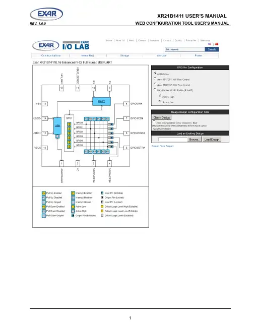
TABLE OF CONTENTS1.0 OVERVIEW (3)2.0 GPIO PIN CONFIGURATIONS (3)2.1 CONFIGURING THE GPIO PINS IN GPIO MODE (3)2.1.1 CONFIGURING GPIO INPUTS (4)2.1.1.1 E NABLING INTERNAL PULL-UP OR PULL-DOWN RESISTORS (4)2.1.1.2 E NABLING GPIO INTERRUPTS (4)2.1.2 CONFIGURING GPIO OUTPUTS (5)2.2 CONFIGURING THE GPIO PINS IN AUTO RTS/CTS FLOW CONTROL MODE (6)2.3 CONFIGURING THE GPIO PINS IN AUTO DTR/DSR FLOW CONTROL MODE (7)2.4 CONFIGURING THE GPIO PINS IN AUTO HALF-DUPLEX TRANSCEIVER ENABLE MODE (8)3.0 USB CONFIGURATIONS (9)3.1 ENTERING A VALID VENDOR ID AND PRODUCT ID (9)3.2 USB MANUFACTURER, PRODUCT, SERIAL NUMBER STRINGS (10)3.3 REMOTE WAKE-UP SUPPORT (10)3.4 SELECTING THE POWER MODE (10)3.5 USB MAX POWER (10)3.6 LOWPOWER PIN POLARITY (10)4.0 UART SETTING CONFIGURATIONS (11)4.1 SELECTING THE CORE CLOCK FREQUENCY (12)4.2 SELECTING THE UART DEFAULT SETTINGS (12)5.0 CHECK DESIGN AND GENERATE CONFIGURATION FILE (12)6.0 XR21B1411 SOFTWARE DRIVER AND OTP PROGRAMMING TOOL (13)7.0 TECHNICAL SUPPORT (14)1.0OVERVIEWThe XR21B1411 Enhanced 1-Channel Full-Speed USB UART has internal One-Time-Programmable (OTP) memory that can be used to customize the default settings of the XR21B1411. The web configuration tool for the XR21B1411 from Exar I/O Lab is shown above and can be accessed from a link on the XR21B1411 product page on Exar’s website. This tool shows a visual representation of how the device will behave upon power-up such as the GPIO settings, UART settings and USB parameters (ie. Vendor ID, Product ID, Device Maximum Power, etc.). Once the XR21B1411 has been configured using this tool, the design configuration can be downloaded and used as an input file for Exar’s OTP programming tool (also available from Exar’s website) to program the XR21B1411 device.This manual provides instruction for configuring the XR21B1411 and provides notes/tips for the various settings that are available. Note that once the XR21B1411 is programmed, no further changes or modifications can be made to the OTP.2.0GPIO PIN CONFIGURATIONSThere are 4 modes available for the GPIO pins. Details of these 4 modes can be found in the XR21B1411 datasheet on Exar’s website. The 4 modes that can be selected are:■GPIO Mode■Auto RTS/CTS HW Flow Control■Auto DTR/DSR HW Flow Control■Auto Half-Duplex Transceiver Enable (typically used for RS-485)2.1Configuring the GPIO pins in GPIO ModeThere are 6 GPIO pins on the XR21B1411. By default, they are General Purpose I/Os that can be configured either as inputs or outputs. In this mode, the defaults for the GPIOs are:■Inputs■Internal pull-up and pull-down resistors disabled■Interrupts are enabled for GPIOs configured as inputs2.1.1Configuring GPIO inputs2.1.1.1Enabling internal pull-up or pull-down resistorsAs an input, a GPIO can have either an internal pull-up or pull-down resistor enabled. The pull-up or pull-down resistor for an input can be configured by clicking on "PU" or "PD" for the desired GPIO input pins (shown in the green circles in the image above). If enabled, the "PU" or "PD" will turn yellow for "enabled". Note that the configuration tool will not allow both to be enabled at the same time. The last block clicked, "PU" or "PD", will determine if the GPIO has an internal pull-up or pull-down resistor enabled. Clicking on the "PU" and "PD" blocks will not have any effects if the GPIO is an output. Also, changing an input to an output will clear any "PU" or "PD" block that has been enabled for that GPIO.2.1.1.2Enabling GPIO interruptsBy default, the GPIO interrupts are enabled. Any GPIO that is an input will generate an interrupt when its input state changes. The GPIO interrupt can be disabled by clicking on the GPIOs in the purple circle in the image above. If a GPIO is configured as an output, the interrupt will automatically be disabled for that GPIO.2.1.2Configuring GPIO outputsBy clicking on the arrows highlighted with the red circle above, the GPIOs will change from inputs to outputs as shown in the image below. Once the GPIO is an output, the block next to the output arrow will turn yellow and display "0" indicating that the default output state will be low upon power-up. Clicking on the this block will change it to a "1" indicating that the default output state will be high upon power-up. An example of this is shown below for GPIO2.2.2Configuring the GPIO Pins in Auto RTS/CTS Flow Control ModeIn Auto RTS/CTS flow control mode, GPIO5/RTS# becomes an output pin and GPIO4/CTS# becomes an input pin. GPIO5/RTS# can not be changed to an input and, similarly, GPIO4/CTS# can not be changed to an output. The configuration is shown below.In this mode, GPIO3-GPIO0 can still be configured as described in “Section 2.1, Configuring the GPIO pins in GPIO Mode” on page 1.2.3Configuring the GPIO Pins in Auto DTR/DSR Flow Control ModeAuto DTR/DSR Flow Control Mode is similar to Auto RTS/CTS Flow Control Mode. In this mode, GPIO3/DTR# is configured as an output and GPIO2/DSR# is configured as an input and their direction can not be changed. The Auto DTR/DSR Flow Control configuration is shown below.In this mode, GPIO5, GPIO4, GPIO1, and GPIO0 can still be configured as described in “Section 2.1, Configuring the GPIO pins in GPIO Mode” on page 1.2.4Configuring the GPIO Pins in Auto Half-Duplex Transceiver Enable ModeThe Auto Half-Duplex Transceiver enable mode is typically used in half-duplex RS-485 applications. In this mode the GPIO5/RTS# pin is used to control the driver enable of an RS-485 transceiver. When this mode is selected, the polarity will also need to be selected as active high or active low.■Active High - The GPIO5/RTS# pin will be low when the UART is not transmitting data and the GPIO5/ RTS# pin will be high when the UART is transmitting data.■Active Low - The GPIO5/RTS# pin will be high when the UART is not transmitting data and the GPIO5/ RTS# pin will be low when the UART is transmitting data.An example of how the Auto Half-Duplex Transceiver enable mode is shown below. The block next to the "TX EN" also shows whether the selected polarity is active high or active low.In this mode, GPIO4-GPIO0 can still be configured as described in “Section 2.1, Configuring the GPIO pins in GPIO Mode” on page 1.3.0USB CONFIGURATIONSBy clicking on the "USB" block, an additional configuration window will appear on the right hand side of the screen, as shown below.3.1Entering a Valid Vendor ID and Product IDIn this new window, the USB parameters can be entered. The configuration tool will have defaults of 0x0000 in the Vendor ID (VID) and Product ID (PID) field. A VID or PID of 0x0000 is not an acceptable and will reported later as an error when the "Check Design" button is pressed if valid IDs have not been entered. If using Exar’s VID (0x04E2) and PID (0x1411), these values will need to be entered. A unique range of PIDs can be requested from Exar by sending an e-mail request to ************************.3.2USB Manufacturer, Product, Serial Number StringsThe default Manufacturer String is "Exar" and Product String is "XR21B1411" if no string values have been entered. There is no default value for the Serial Number String. If one string is entered, then all three strings need to be updated or they will not have a value when the OTP is programmed. Entering a value for the Serial Number String is optional.3.3Remote Wake-up SupportBy default, remote wake-up support is enabled. This can be disabled by unchecking the box. Note that if the software driver does not have the remote wake-up feature enabled, then the XR21B1411 will not issue a remote wake-up signal when a remote wake-up event occurs. Note that the standard CDC-ACM driver does not support the Remote Wake-up feature.3.4Selecting the Power ModeBy default, bus-powered mode is enabled. The XR21B1411 can be configured for self-powered mode by checking the box next to "Self Powered". For self-power mode, it is recommended that the box next to "Enable VBUS Sense" also be checked. The VBUS Sense feature disables the internal pull-up resistor on the USBD+ pin when there is no power on the VBUS pin. This is required for USB compliance. If the VBUS Sense feature is not available, then an external mechanism is required to disable the power supply to the XR21B1411.3.5USB Max PowerBy default, the USB maximum power is configured as 100 mA. This is the maximum for a low power device, as described in the USB specifications. Any board that requires more than 100 mA from VBUS will be considered a high power device. The maximum allowable supply current is 500 mA for a high power device. The USB max power can be changed by clicking on the arrows on either end of the scroll bar or by dragging the horizontal scroll bar.3.6LOWPOWER Pin PolarityThe default polarity of the LOWPOWER pin (pin 1) is active high as shown in the drawing. The polarity can be changed by clicking on the box below the USB block in the drawing. The inner circle will become yellow to indicate that the LOWPOWER pin is now active low.XR21B1411 USER’S MANUAL REV. 1.0.0WEB CONFIGURATION TOOL USER’S MANUAL 4.0UART SETTING CONFIGURATIONSClicking on the "UART" block will remove the USB Configuration window and display the "UART Configuration Window" as shown below.XR21B1411 USER’S MANUALWEB CONFIGURATION TOOL USER’S MANUAL REV. 1.0.0 4.1Selecting the Core Clock FrequencyThe available core clock frequencies are 6 MHz, 12 MHz, 24 MHz and 48 MHz. The selection of the core clock frequency will affect the maximum baud rate and the power consumption. The maximum baud rate can be calculated by dividing the core clock frequency by 4.■6 MHz core clock frequency => 1.5 Mbps maximum baud rate■12 MHz core clock frequency => 3 Mbps maximum baud rate■24 MHz core clock frequency => 6 Mbps maximum baud rate■48 MHz core clock frequency => 12 Mbps maximum baud rateFor details of how much power the XR21B1411 consumes with each core clock frequency, refer to the XR21B1411 datasheet on Exar’s website. Note that the higher the core clock frequency, the more power it consumes. If an application is battery-powered, it will be beneficial to use a 6 MHz core clock frequency if baud rates above 1.5 Mbps do not need to be supported.4.2Selecting the UART default settingsDefault baud rates and character formats can be entered and selected. Most standard software drivers and applications will typically initialize the UART settings. However, this may be helpful for custom software drivers and/or software applications that do not initialize/configure the UART settings.5.0CHECK DESIGN AND GENERATE CONFIGURATION FILEOnce all of the desired configurations have been entered or selected, click on the "Check Design" button. This will check to see if there are any errors. If there are errors, then a pop-up message, as shown below, will appear indicating the error and a button to go back to the correct page to fix it.XR21B1411 USER’S MANUAL REV. 1.0.0WEB CONFIGURATION TOOL USER’S MANUAL In this example, the VID and PID were not entered. Clicking on "Back to USB" will bring up the "USB Configuration" block where the VID and PIDs can be entered. Once the error has been fixed, click "Check Design" again. If there are no errors, then a pop-up window similar to the one below will appear.Click on "Download Design File" to view and save the generated file. The file will have a ".xml" extension. This saved file can be used at a later date by loading it using the "Load an Existing Design" block.6.0XR21B1411 SOFTWARE DRIVER AND OTP PROGRAMMING TOOLThe XR21B1411 Software Driver and OTP Programming Tool can be downloaded from Exar’s website. The software driver needs to be installed before the OTP Programming Tool can be used. It is recommended that the configuration be carefully reviewed before programming the OTP memory. Once the OTP memory has been programmed, it can not be un-programmed. It is also recommended that samples be programmed and tested before programming in volume.NOTICEEXAR Corporation reserves the right to make changes to the products contained in this publication in order to improve design, performance or reliability. EXAR Corporation assumes no responsibility for the use of any circuits described herein, conveys no license under any patent or other right, and makes no representation that the circuits are free of patent infringement. Charts and schedules contained here in are only for illustration purposes and may vary depending upon a user’s specific application. While the information in this publication has been carefully checked; no responsibility, however, is assumed for inaccuracies.EXAR Corporation does not recommend the use of any of its products in life support applications where the failure or malfunction of the product can reasonably be expected to cause failure of the life support system or to significantly affect its safety or effectiveness. Products are not authorized for use in such applications unless EXAR Corporation receives, in writing, assurances to its satisfaction that: (a) the risk of injury or damage has been minimized; (b) the user assumes all such risks; (c) potential liability of EXAR Corporation is adequately protected under the circumstances.Copyright 2010 EXAR CorporationDatasheet September 2010.Send your UART technical inquiry with technical details to hotline: ************************.Reproduction, in part or whole, without the prior written consent of EXAR Corporation is prohibited.XR21B1411 USER’S MANUALWEB CONFIGURATION TOOL USER’S MANUALREV. 1.0.07.0TECHNICAL SUPPORT If there are any questions about the web configuration tool, configuration file or the XR21B1411, send your questions to ************************.。
包装清单部件名称电源管理充电连接正在更新固件入门指南 _01基本操作主屏幕通知面板从商店购买音乐DLNA Link 聆听音乐播放列表管理设置连接至无线网络使用 Bluetooth 均衡器设置设备使用 _02安全预防措施故障排除版权注册商标免责声明规格其他注意事项 _03目录020*********11151719202326293435374042434444455 针微型 USB 电缆: 将本产品连接到 PC 或给本产品充电。
快速入门指南: 介绍使用本产品的基本方法。
保修卡: 如需客户服务,必须提供保修卡。
用户指南: 您可从以下 Activo 网址中下载用户指南: [http: /// > 支持 > 下载]。
为提高产品的性能或质量,恕不预先通知任何内容变更。
包装清单和保修卡USB 电缆5 针微型 USB 端口: 连接到计算机或对设备充电。
3.5 毫米不平衡: 用 3.5 毫米不平衡端口连接入耳式耳机和头戴式耳机以输出声音。
电源: 短按 - 打开或关闭屏幕。
长按 - 打开和关闭设备。
上一首/快退: 短按 - 播放上一首歌曲或者重新开始播放该歌曲。
长按 - 快退。
播放/暂停: 播放/暂停。
下一首/快进: 短按 - 播放下一首音乐。
长按 - 快进。
microSD: 将 microSD 卡插入产品,以查看 microSD 卡中的文件。
音量: 转动滚轮可调整音量。
LCD 触摸屏: 显示屏幕,并且触摸屏幕即可启动。
主按钮: 返回主屏幕。
产品外观以及产品上的印刷和刻印信息可能因型号不同而有所差异。
部件名称上一首/快退下一首/快进播放/暂停microSD触摸屏 LCD 主按钮音量电源重置功能1. 如果出现意外设备故障或者冻结,长按 [电源] 7 秒可强 制进行关闭。
关闭后可以重新启动设备。
32 打开/关闭屏幕1. 打开屏幕后,短按 [电源] 键关闭屏幕。
2. 再次短按 [电源] 键打开屏幕。
迷你音响说明书迷你音响说明书篇一:便携式高保真迷你音响说明书9(1) 迷你音响说明书篇二:INTEMPO音箱简洁说明书INTEMPO音箱简洁说明书基本配件:主机1XX遥控器1个欧版电源插头线1根美版电源插头线1根3.5mm转接线1根多国语言版说明书1本Wrrnty卡1张反面〔上图左〕说明从左到右分别为开关按钮,电源插头,广播天线,USB接口,立体声输入端口。
正面〔上图右〕说明从左到右分别为休眠电源开关,红外线接收口,液晶显示屏,苹果专用底座,6个小按钮操纵键,2个大按钮操纵键。
功能介绍:本音箱具有高品质放音功能,主要分为三大类不同音源:1.FM收音机2.ipod/iphone等苹果专用接口设备放音3.任何有3.5mm接口的音源设备放音。
三种模式可以通过按6个小按钮中的“Mode〞键进行切换。
本音箱具有闹钟和时间功能闹钟功能使用:1. 按6个小按钮中的“lrm〞键,按1下为设置闹钟1,按2下为设置闹钟2.2.按上、下箭头键进行调整闹钟是否打开。
“On〞为开启,“Off〞为关闭。
3.按“Select〞键。
4.按上、下箭头键选择闹钟的“小时〞。
5. 按“Select〞键。
6.按上、下箭头键选择闹钟的“分〞。
7. 按“Select〞键。
8. 按上、下箭头键选择闹钟的“持续时间〞,有15,30,45,60,90等可以选择。
9. 按“Select〞键。
10. 按上、下箭头键选择闹钟铃声〔可以是ipod的音乐,也可以是收音机等等〕11. 按“Select〞键。
闹钟设置完毕。
FM收音机调整1. 按6个小按钮中的“Mode〞键进行切换到FM模式。
2. 按左、右箭头键选择您要的频率。
ipod/iphone等苹果专用接口设备放音1.按压机身中的dock,弹出苹果专用底座,并插入您的苹果设备。
2. 按6个小按钮中的“Mode〞键进行切换到ipod模式。
3.通过面板中的播放操纵键或者遥控器进行操纵音乐播放。
任何有3.5mm接口的音源设备放音1.将随机附赠的3.5mm接口线的一端插入机身反面的3.5mm圆孔。
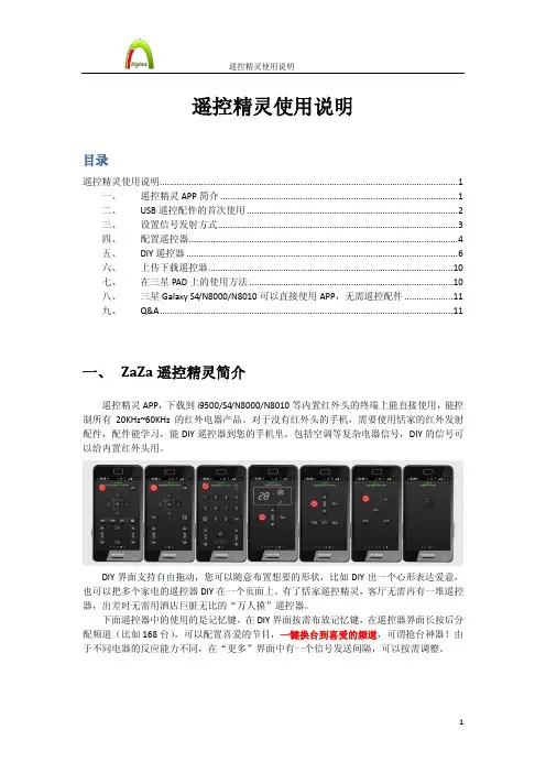
遥控精灵使用说明目录遥控精灵使用说明 (1)一、遥控精灵APP简介 (1)二、USB遥控配件的首次使用 (2)三、设置信号发射方式 (3)四、配置遥控器 (4)五、DIY遥控器 (6)六、上传下载遥控器 (10)七、在三星PAD上的使用方法 (10)八、三星Galaxy S4/N8000/N8010可以直接使用APP,无需遥控配件 (11)九、Q&A (11)一、ZaZa遥控精灵简介遥控精灵APP,下载到i9500/S4/N8000/N8010等内置红外头的终端上能直接使用,能控制所有20KHz~60KHz的红外电器产品。
对于没有红外头的手机,需要使用恬家的红外发射配件,配件能学习,能DIY遥控器到您的手机里,包括空调等复杂电器信号,DIY的信号可以给内置红外头用。
DIY界面支持自由拖动,您可以随意布置想要的形状,比如DIY出一个心形表达爱意,也可以把多个家电的遥控器DIY在一个页面上。
有了恬家遥控精灵,客厅无需再有一堆遥控器,出差时无需用酒店巨脏无比的“万人摸”遥控器。
下面遥控器中的使用的是记忆键,在DIY界面按需布放记忆键,在遥控器界面长按后分配频道(比如168台),可以配置喜爱的节目,一键换台到喜爱的频道,可谓抢台神器!由于不同电器的反应能力不同,在“更多”界面中有一个信号发送间隔,可以按需调整。
记忆键还能把好几个遥控器的按钮按顺序排列在一起,一键遥控多个电器。
APP下载地址:/icontrol/app/icontrol.apk二、USB遥控配件的首次使用3, 配件联网校验完毕,遥控器界面(下图)状态条转绿,可以开始使用了;小米1S 需要带着配件重启一次手机来完成硬件识别。
USB 配件无需充电,能力等同原装遥控器。
三、 设置信号发射方式安装APP 。
运行APP ,系统会自动按照您插入的配件帮您选好驱动。
您也可以手动切换,进入“更多”页面,在“设备选择”中手动选择您的机型(有内置红外头)或拥有的配件(USB 接口、音频接口zaza )。
便携式多媒体音响使用说明书专注于完美音质的追求…………..感谢您使用本公司除频的数码产品,为了让您轻松体验产品,我们随机配备了内容详尽的使用说明,您从中可以获取有关产品的介绍,使用方法等方面的知识。
在您开始使用本机之前请先仔细阅读说明书,以便您能正确的使用本机,如有任何印刷错误或翻译失误望广大用户谅解,当涉及内容有所更改时,恕不另行通知。
一、产品概述本机是一款外观小巧、设计精美、携带方便多媒体小音响,适用于家居、户外旅游、办公室等场所,随机随地享受音乐带来的轻松,为您的电脑、数码音乐播放器、手机等视听产品提供您超值完美的音质二、功能特点【MP3播放】直接播放TF卡及U盘MP3文件【FM收音机】FM数字立体声收音机,电台记忆播放。
(可选机型,功能以实物为准)【外挂耳机】本机配置标准耳机插孔,可选配耳机聆听音乐【音频输入】立体生意频输入接口,轻松接驳电脑、数码音乐播放器、手机等视听产品各类音源【断点记忆】自动记忆上次退出时的曲目播放【可充锂电】内置可充电锂电池,环保、节约、实用【智能充电】配送U SB接口充电线,可接驳电脑的USB接口进行充电,或实用手机充电器进行充电三、播放音乐操作本机的微电脑系统自动检测识别外接设备,开机后进行待机模式,插入U盘或TF存储卡自动识别播放,后者优先原则,祥细功能操作请阅读第四项“产品的按键、插孔功能定义”四、产品的按键、插孔功能定义(以实物为准)1、【】:长按开机/关机,播放/暂停2、【】:短按上一曲,选择上一个收音电台,长按调节音量减少3、【】:短按下一曲,选择下一个收音电台,长按调节音量增大4、【mode】:模式转换键,短按转为USB/SD模式,再短按为LINE IN(AUX音频输入模式),在FM收音机模式,长按为自动搜台并记忆保存电台5、【DC-5V/Ω】:电源输入+耳机共用插孔,可以插耳机欣赏音乐或收听电台:电源输入插孔,可使用本机配送的专用USB电源线,接驳电脑的USB接口进行充电,或使用手机充电器进行充电。
不见不散RV77简易操作指南(一).播放音乐1)短按【】键,选择“TF卡音乐”模式。
(每次开机,系统自动选择此模式)。
2)开始自动播放音乐,短按【】暂停,再按一次继续播放。
3)短按【】选择下一首歌;短按【】选择上一首歌。
4)长按【】音量加;长按【】音量减。
(二)播放广播1)短按【】键,选择“调频广播”模式。
2)开始播放广播,短按【】静音,再按一次恢复。
3)短按【】选择下一频道;短按【】选择上一频道。
4)长按【】音量加;长按【】音量减。
5)长按【】键是自动收索电台并自动存储。
桂林能收到的电台已经帮您存储好。
只要不去外地,不需要启动此功能。
离开桂林市则需要重新收索电台。
6)需要加强接收信号时将加强天线插到绿色孔中,黑色是耳机。
(三)充电当电量不足时会有语音提示。
关机充电:机子上指示灯红色,充电完成后指示灯灭;充电器上指示灯是一直绿色,无论充电是否结束,都不变色。
(四)插拔TF卡1)有字的一面朝上插入机子,再按一次则弹出,每次插拔会听见咔嚓声。
2)有字的一面朝上插入读卡器,取出时直接拔出,不会听见咔嚓声。
山水D10简易操作指南(一).播放音乐1)短按【】键,选择“SD或USB卡音乐”模式。
(每次开机系统自动选择此模式)。
2)开始自动播放音乐,短按【】暂停,再按一次继续播放。
3)短按【】选择下一首歌;短按【】选择上一首歌。
4)音量加、减用调音滚轮控制。
(二)播放广播1)短按【】键,选择“调频广播”模式。
屏幕上会显示电台频率。
2)长按【】,机子自动收索电台并自动保存。
桂林能收到的电台已经帮您存储好。
只要不去外地,不需要启动此功能。
离开桂林市则需要重新收索电台。
3)开始播放广播,短按【】选择下一个存好的频道,不能回选,只能单方向循环选择。
4)短按【】键是手动回退搜索电台;短按键是手动向前搜索电台。
一般情况下不用手动搜索电台,用3)的方式即可。
(三)模式切换按下【】键,机子功能在“SD卡和USB卡---收音---音箱”三个功能之间循环切换,每按一次切换一个。
谷轮™涡旋灵冻™系列ZXV变频冷凝机组产品手册谷轮™涡旋灵冻™系列ZXV 变频冷凝机组艾默生为客户提供灵动系列的ZXV/ZXLV 直流变频冷凝机组,专为冷冻应用而设计。
总体而言,ZX 平台冷凝机组(ZX 和ZXB 中温,ZXL 低温,ZXD/ZXLD 数码变容量中温和低温,ZXV/ZXLV 直流变频中温和低温制冷)在全球尤其亚洲市场取得了巨大的成功,并以其节能和友好的电子控制功能获得普遍认可。
声明感谢您购买艾默生ZXV 冷凝机组。
ZX 平台的冷凝机组与市场上同类产品相比,其制冷能力与运行范围均表现出众,ZX 冷凝机组专为中温和低温制冷应用而设计,具有高可靠性和高效率的特点,并能持续监控压缩机运行状态,显示冷凝机组的运行或故障状态。
安装ZX 平台的冷凝机组必须遵循行业贸易惯例,以确保其安全可靠地运行。
冷凝机组应由专业人员选型、安装和维修。
本用户手册并未包含所有制冷设备安装需遵循的行业准则。
对于由无经验或未经专业培训的人员操作、或由于错误的安装设计造成的损失,将不作为合理的追责理由。
如有任何疑问,请向当地销售办公室提供机组铭牌上的机组型号和序列号进行咨询。
如随机附带的接线图与本手册中的接线图发生不符情况,请以随机附带的接线图为准。
ZX 平台冷凝机组简介ZX 和ZXB 中温、ZXL 低温、ZXD/ZXLD 数码变容量中温和低温、ZXV/ZXLV 变频中温和低温系列在亚洲市场取得了巨大成功,并以其节能和用户友好的电子控制功能享誉市场。
ZX 平台冷凝机组在亚洲范围内应用于著名的终端用户和冷链零售商现场。
灵冻系列平台产品在全球市场上得到广泛认可,特制开发的机型已出口美国、欧洲和中东市场。
收到机组的检查所有机组运输前均充有一定正压的干氮气。
机组和包装均贴有明显的标签。
机组截止阀上配有维修接口以便检查机组保压状态。
注意!当您从艾默生或授权代表处收到机组时,对每一台机组进行保压检查是非常重要的。
如发现保压已消失,请联系艾默生或授权代表。
12遥控精灵使用说明一、恬家产品介绍恬家(上海)信息科技专注于为手机、PAD开发APP及外设,让用户感到快乐是我们的追求,“快乐恬家”是我们的座右铭。
2012年3月公司创立以来,恬家一直致力于APP与外设开发的能力构建上,遥控精灵是我们的第一个产品。
遥控精灵最大同时加载276个遥控器,1万2千个按钮,多套皮肤。
能遥控频段在35~45KHz的全部红外设备。
预置百余种遥控器。
用户可以DIY自己的遥控器并署名,通过恬家云在线上传下载红外码并评论。
Micro USB接口的遥控精灵目前支持的机种如下:手机:三星i9100/ i9100G/ i9220/ i9250/ i9300,华为D1,小米2,索爱LT181PAD:三星P6800/ P5100/ P5110/ P6200/ P3100,华为mediapad10 FHD,Google Nexus 7 其它:Android3.1或以上,使用MICRO-B USB接口并支持OTG技术的手机、PAD比如昂达、酷比、蓝魔、原道、索尼的部分产品恬家将在底月发布支持蓝牙接口的遥控精灵,支持Android2.1以后的所有带蓝牙功能的手机。
遥控精灵外设购买请到:二、添加遥控器1.在遥控器界面,可上下滑动切换本遥控器,显示更多按钮功能;也可左右滑动屏幕切换遥控器。
需要添加遥控器时,可滑动至本场景末尾(当前界面下方有小圆点标签示意)2.点击界面中央添加按钮,界面跳转3.可在输入窗口内输入电器品牌或电器型号等信息进行数据检索,界面下方可选择遥控器皮肤(包括背景颜色及按钮类型),点击所选遥控器,确定,即完成遥控器添加。
三、添加场景1.进入遥控精灵场景界面,点击添加按钮(如下图)2.选择此场景内需要添加的一个遥控器(方法请参考添加遥控器)3.选择遥控器后,界面跳转,选择一个场景图标,恬家已经为用户取了一些常用场景的名称,用户也可以自定义和更改,点击完成确认后,添加场景成功。
4. 一个场景中包含有1个或多个遥控器,在场景界面,用户可以长按场景图标,选择设置主界面,重命名,删除场景等选项。