Electricity generation from wastewaters with starch as carbon source
- 格式:pdf
- 大小:380.42 KB
- 文档页数:5

微生物燃料电池12级新能源材料,程妮,学号106微生物燃料电池(microbial fuel cells ,MFCs)是一种利用微生物作为催化剂,将燃料中的化学能直接转化为电能的装置,是一种生物反应器。
自1911年英国植物学家Potter 发现微生物可以产生电流开始,有关MFCs 的研究一直在进行,但进展缓慢。
直到研究人员发现某些微生物能在无介体的条件下直接将体内产生的电子传递到电极,MFCs 的研究获得了突破性进展。
目前,MFCs 研究的主要内容是无介体MFCs 产电性能的改善,体现在污水处理、生物传感器的应用和生物修复等方面。
一、原理微生物燃料电池以附着于阳极的微生物作为催化剂,通过降解有机物(例如,葡萄糖、乳酸盐和醋酸盐等),产生电子和质子。
产生的电子传递到阳极,经外电路到达阴极产生外电流。
产生的质子通过分隔材料(通常为质子交换膜、盐桥),也可以直接通过电解液到达阴极。
在阴极与电子、氧化物发生还原反应,从而完成电池内部电荷的传递。
如图所示为MFCs 的工作原理示意图。
典型反应如下:阳极:C 6H 1206+6H 20一6C02+24H ++24e -阴极:602+24H ++24e -一一12H 20二、微生物燃料电池的结构微生物燃料电池主要有三种结构类型,即单室结构、双室结构和填料式结构。
[1](一)、单室结构的MFCs 单室MFCs 通常直接以空气中的氧气作为氧化剂,无需曝气,因而具有结构简单、成本低和适于规模化的优势。
单室的功率密度为480~492mW /m 2,单室MFCs 无分隔材料和阴极液,内阻较双室小。
但是单室MFCs 的库仑效率(CE)比双室低(单室库仑效率为10%,而双室则为42%~61%)。
(二)、双室结构的MFCs 典型的双室MFCs 包括阳极室和阴极室,中间由PEM 或盐桥连接。
双室的功率密度为38~42mW /m 2。
MFCs 从外形上又分为平板型和管型。
以厌氧污泥为活性微生物,以葡萄糖为底物,以颗粒石墨为阳极的管状ACMFCs,其最大功率密度达到50.2W/m2。

雅思小作文电力发电英文回答:Electricity generation is an essential part of ourdaily lives. It powers our homes, businesses, and industries, providing us with the energy we need to function. There are various methods of generating electricity, each with its own advantages and disadvantages.One common method of electricity generation is through the use of fossil fuels, such as coal, oil, and natural gas. These fuels are burned in power plants to produce steam, which then drives turbines to generate electricity. This method has been widely used for many years due to its reliability and relatively low cost. However, it is also a major contributor to air pollution and greenhouse gas emissions, which have detrimental effects on the environment and human health.Another method of electricity generation is throughrenewable energy sources, such as solar, wind, hydro, and geothermal power. These sources are considered more sustainable and environmentally friendly compared to fossil fuels. For example, solar panels convert sunlight into electricity, while wind turbines harness the power of wind to generate electricity. These methods do not produce harmful emissions and have the potential to significantly reduce our carbon footprint. However, they are often more expensive to implement and may require large land areas or specific geographical conditions.In recent years, there has been a growing focus on the development of nuclear power as a means of electricity generation. Nuclear power plants use nuclear reactions to produce heat, which is then used to generate electricity. This method is highly efficient and produces large amounts of electricity without emitting greenhouse gases. However, it also comes with safety concerns and the issue of nuclear waste disposal, which poses long-term environmental risks.Overall, the choice of electricity generation method depends on a variety of factors, including cost,availability of resources, environmental impact, and technological advancements. It is important to strike a balance between meeting our energy needs and protecting the environment. Governments and industries should invest in research and development of sustainable and clean energy solutions to ensure a brighter and greener future.中文回答:电力发电是我们日常生活中不可或缺的一部分。
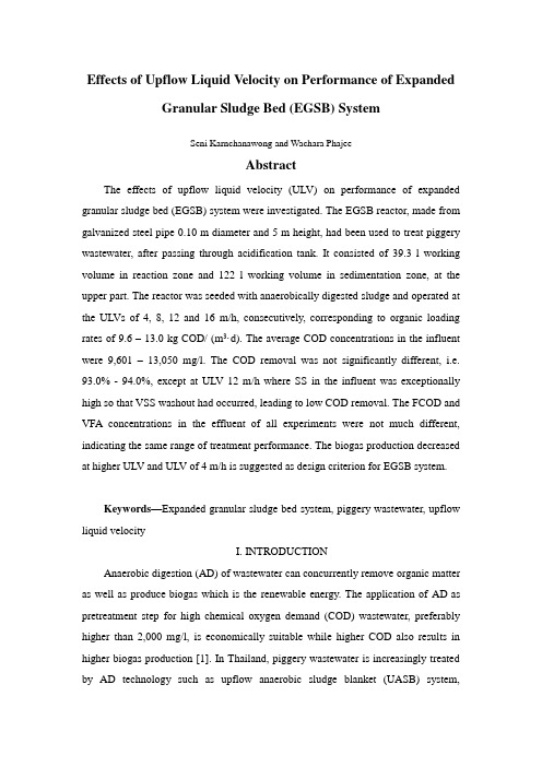
Effects of Upflow Liquid Velocity on Performance of Expanded Granular Sludge Bed (EGSB) SystemSeni Karnchanawong and Wachara PhajeeAbstractThe effects of upflow liquid velocity (ULV) on performance of expanded granular sludge bed (EGSB) system were investigated. The EGSB reactor, made from galvanized steel pipe 0.10 m diameter and 5 m height, had been used to treat piggery wastewater, after passing through acidification tank. It consisted of 39.3 l working volume in reaction zone and 122 l working volume in sedimentation zone, at the upper part. The reactor was seeded with anaerobically digested sludge and operated at the ULVs of 4, 8, 12 and 16 m/h, consecutively, corresponding to organic loading rates of 9.6 – 13.0 kg COD/ (m3·d). The average COD concentrations in the influent were 9,601 –13,050 mg/l. The COD removal was not significantly different, i.e.93.0% - 94.0%, except at ULV 12 m/h where SS in the influent was exceptionally high so that VSS washout had occurred, leading to low COD removal. The FCOD and VFA concentrations in the effluent of all experiments were not much different, indicating the same range of treatment performance. The biogas production decreased at higher ULV and ULV of 4 m/h is suggested as design criterion for EGSB system.Keywords—Expanded granular sludge bed system, piggery wastewater, upflow liquid velocityI. INTRODUCTIONAnaerobic digestion (AD) of wastewater can concurrently remove organic matter as well as produce biogas which is the renewable energy. The application of AD as pretreatment step for high chemical oxygen demand (COD) wastewater, preferably higher than 2,000 mg/l, is economically suitable while higher COD also results in higher biogas production [1]. In Thailand, piggery wastewater is increasingly treated by AD technology such as upflow anaerobic sludge blanket (UASB) system,anaerobic pond, channel (plug flow) digester and anaerobic covered lagoon. The biogas is generally used for on-farm electricity generation via induction motor. UASB system is the high-rate wastewater treatment process where wastewater is fed at the bottom and flows upward, passing through layers of anaerobic bacteria with upflow liquid velocity (ULV) 0.5 –1.5 m/h. The bottom layer, referred to as sludge bed, consists of granules with high suspended solids (SS) concentration (~1-5 %) while the upper layer, referred to as sludge blanket, consists of flocculent sludge (SS ~ 0.3-0.5 %). The granule has very high settling velocity as well as treatment efficiency since it consists of layers of bacteria, responsible for various anaerobic digestion steps [2]. The biogas produced is separated by gas-solids separator (GSS) installed at the upper part of reactor while sedimentation zone, above GSS, help SS removal as well as return it back to reactor. The reactions occur under enclosed part and smell is minimal.To improve the efficiency of UASB system, high ULVs (5 -15 m/h) were applied by effluent recycling and resulted in sludge bed expansion throughout the reactor’s height. The high total biomass allowed the improved system, called expanded granular sludge bed (EGSB) system, to accommodate higher organic loading rate (OLR) than UASB system [3]. Since EGSB system is recommended for low SS wastewater, the application on piggery wastewater which has high SS should be firstly verified by laboratory experiment. Moreover, high ULV results in high pumping cost which should be minimized. The objective of this study was to determine the effects of ULV on performance of EGSB system as well as to determinethe suitable ULV for piggery wastewater treatment.II. MATERIAL AND METHODSThe laboratory scale EGSB reactor, made from galvanized steel pipe 0.10 m diameter and 5 m height with digestion volume of 39.3l, was used. The upper part of reactor was sedimentation zone, made from steel plate 0.5 m diameter, 0.6 m height with 0.10 m freeboard and working volume of 122l (Fig. 1). The biogas was measured by gas meter, i.e. revolving boxes with counter. There were 17 sampling ports along reactor’s height at 0.3 m spaci ng. The major sampling ports were at 0.4,1.9, 3.4 and 4.6 m – height. The piggery wastewater was biweekly collected from2 pig farms, firstly Kittiwat Farm and secondly Chomthong Farm. The wastewater was stored in 0 –4 C storage room prior to using. It was daily prepared in 70-l plastic tank equipped with mechanical mixer (EYELA model MDC-MS). The wastewater was pumped by a peristaltic pump (Watson Marlow model 505s) to the complete-mix acidification tank, operated at 8-h hydraulic retention time (HRT). The acidification tank was made from plastic water tank, 0.25 m diameter, 0.30 m height and working volume of 12.8l. The complete -mix condition was maintained by a circulating pump, submersible type (8.5 watts). There was no seeding in acidification reactor. The acidification tank effluent was pumped to EGSB reactor at the rate of 1.6 l/h with expected OLR of 10 kg COD/ (m3·d). The EGSB effluent was stored in a 70-l plastic tank and was recycled by a peristaltic pump (Watson Marlow model 505s) to control ULV at 4, 8, 12 and 16 m/h, consecutively. The EGSB reactor was seeded with anaerobi cally digested sludge from Chiang Mai University wastewater treatment plant at 25,000 mg VSS/l. During start up period, OLR and ULV were stepwise increased to the target values. The water samples were taken 2 times/week and analyzed according to Standard Methods [4]. The experiments had been conducted under ambient temperature, tropical climate at the Department of Environmental Engineering, CMU, Thailand, during May 2003 to May 2004.III. RESULTS AND DISCUSSIONThe piggery wastewater was firstly collected from Kittiwat Farm. During the last period of run 1, this farm which was medium- sized sometimes did not have uniform wastewater flow rate so a bigger farm, Chomthong Farm, was chosen throughout the study. The wastewater characteristics had high fluctuations of COD and SS and the acidification tank helped stabilizing the wastewater concentrations. The performance of acidification tank was rather poor, i.e. COD removal 0 – 5%, VSS removal 2.2 –27.6%. There was no pH adjustment in acidification tank. The influent pH was in neutral range, 6.8 -8.0, while the effluent pH was slightly decreased, 6.8 -7.8. The effluent VFA from acidification were not significantly increased and sometimes slightly decreased, indicating methanogenesis in reactor. It is expected that bacterial enrichment from pig feces plays an important role inVFA degradation. TheFig. 1 Experimental set-upeffluent of acidification tank was further fed to EGSB reactor, initially at OLR 2kg COD/ (m3·d) and ULV 0.5 m/h. The OLRs were stepwise increased to 10 kg COD/( m3·d) at ULV 4 m/h. It took about 3 months to start up the EGSB system before the study period. The system was then operated at various durations as follows; run 1 (ULV 4 m/h) 165 d, run 2 (ULV 8 m/h) 76 d, run 3 (ULV 12 m/h) 56 d, run 4 (ULV 16m/h) 77 d, consecutively. It was found that the influent COD and SS concentrations varied, causing effluent value fluctuations in run 3. During the study, there was no biomass withdrawal from the reactor, except via effluent. The results of COD and SS variations throughout the study are shown in Fig. 2 and 3, respectively.In run 1, the EGSB influent characteristics had average values as follows; COD 9,601 mg/l, Filtered COD (FCOD) 1,514 mg/l, VFA 1,083 mg/l as acetic acid, SS 1,829 mg/l, VSS 1,530 mg/l. In run 2- 4, the average values are as follows; COD 11,355- 13,050 mg/l, Filtered COD (FCOD) 1,720 -2,300 mg/l, VFA 784 - 1,360 mg/l as acetic acid, SS2,930 - 6,590 mg/l, VSS 1,390 - 4,310 mg/l. The EGSB influent had low FCOD:COD ratios, i.e. 0.15 –0.18, and high VSS:SS ratios, i.e. 0.47 –0.87.These indicated that high proportion of organics was in suspended form which was biologically degradable. In run 3, the influent SS was exceptionally high, causing biomass flushing from EGSB reactor. The peak effluent COD was found to be 8,460 mg/l on the 284th day of study period while FCOD did not increase (Fig. 2). The biomass eventually adapted to high ULV and resumed to normal operating condition during the later period of run 3. The steady-state condition in run 3 therefore could not be concluded. Although the OLR in all runs was expected to be uniform at 10 kg COD/ (m3·d), the fluctuations in influent COD concentrations resulted in actual OLRs of 9.6-13.0 kg COD/ (m3·d). The overall performance of EGSB at various ULV is summarized in Table I.Fig. 2 COD variationsFig. 3 SS variationsThe performance of EGSB system in terms of COD removal was in the same ranges (93.0 –94.0%), except in run 3 where effluent suspended biomass (VSS) caused poor COD removal (38.1%). The VFA and FCOD in the effluent, i.e. 94-162 mg/l as acetic acid and 330- 512 mg/l, respectively, were not much different, indicating the relatively stable performance. However, heavy biomass flushing in run 3 showed the higher effluent SS concentrations, as presented in Table I, with 45.0% removal. Once the influent SS decreased and the system adjusted to the applied ULV, the EGSB system resumed to normal operating condition. In run 4 where ULV 16 m/h was applied, the SS removal was found to be 88.0%. It is suggested that EGSB system should be operated at influent SS concentration less than 5,000 mg/l, if high COD andRemark : (1) Average values during steady-state conditions(2) Average values during 284th– 298th day of study periodSS removal (>80%) is needed. The periodic SS withdrawal from reactor is also recommended if low SS in the effluent is required. Based on FCOD, there was nosignificant difference in system performance in terms of organic matter removal at ULV 4 – 16 m/h. The biogas measured had proportionally decreased with increasing ULV. It is expected that biogas volatilization, from excessive dissolving capacity in recycle tank, may be responsible in high effluent recycling condition. The methane (CH4) composition also slightly decreased at higher ULV along with biogas production. The other major gas compositions were nitrogen (17.5 - 27.2%) and carbon dioxide (3.4 - 3.8%). The carbon dioxide content was relatively low as compared to normal UASB reactors [1, 5]. Based on biogas production and recycling cost of effluent, ULV 4 m/h is suggested as design criterion. There was no pH adjustment in EGSB reactor and the system pH, 7.5-8.3, were slightly higher than optimum range for anaerobic process, i.e. 6.5-7.5 [6]. The influent VFA: alkalinity ratios were 0.37-0.54. The average total phosphorus (TP), NH4-N and TKN concentrations in the influent of 4 runs were 21.1-65.2, 113 – 181 and 551 – 634 mg/l, respectively. The COD:N:P ratios in the influent of 4 run were 600:29.4:1.2 –600:33.6:4.2 which were sufficient as compared to the suggested ratio 600:7:1, indicting enough macro nutrients for bacterial cell synthesis[7]. The advantage of EGSB system over UASB system is higher biomass accumulation since higher ULV will expand the sludge bed layer upward through the reactor’s height [3].The vertical solids profile confirmed this assumption, where high concentrations of SS (> 1%) were found along the reactor, as shown in Fig. 4. This solids profile pattern was different from UASB reactor [5], and similar to other EGSB study [8]. However, very high SS concentration (>5%) were found at the bottom layer.The solids distribution and total biomass throughout the study are summarized in Table II.According to Table II, the total biomass did not much differ during the study period. The water samples at the reactor’s height of 0.4, 1.9, 3.4 and 4.6 m were periodically taken. It was found that COD, FCOD and VFA decreased vertically from the bottom to the top of reactor, according to reactions occurred during upflowing. The granules were measured by microscope. The average granule sizes at 0.4 m from bottom were highest (0.33-0.50 mm) while at 3.4 –4.6 m were smaller (0.17-0.20mm).The EGSB granules were much smaller than UASB granules and the flocculent sludge did not present in EGSB reactor as compared to UASB reactor [5]. The high ULV obviously flushed out the floc and low density sludge. The EGSB granule appeared to be round shape and more uniformly distributed than UASB granules [5]. During the study, the scale of struvite (MgNH4PO4 .6H2O, Magnesium Ammonium Phosphate) was found in recycle tubes. The piggery wastewater is favorable for struvite precipitation due to high magnesium, ammonia and phosphorus, as observed in other study. Periodically cleaning of recycling facility is also required.Fig.4 Vertical solids profile of EGSB reactor (run 1, 150th day)IV. CONCLUSIONBased on the results obtained, the following conclusions can be drawn. The performance in terms of organic matter removal of EGSB system at ULV 4 to 16 m/h is not significantly different. The influent SS concentration should be less than 5,000 mg/l to prevent solids wash out. The high ULV results in lower biogas production and ULV 4 m/h is suggested as suitable design criterion.Remark :Data at the beginning and the end of each runACKNOWLEDGMENTThe research support from Faculty of Engineering, Chiang Mai University is gratefully appreciated.REFERENCES[1] G. Lettinga, A.F.M. Van Velson, S.W. Hobma, W. de Zeeuw and A. Klapwijka, ―Use of Upflow Sludge Blanket (UASB) Reactor Concept for Biological Wastewater Treatment Especially of Anaerobic Treatment‖, Biotechnol. Bioeng., vol. 22, 1980, pp. 699-734.[2] F.A. McLoed, S.R. Guiot and J.W. Costerton, ―Layered Structure of Bacteria Aggregates Produced in an Upflow Anaerobic Sludge Bed and Filter Re actor‖, Applied & Env. Micro., vol. 56, 1990, pp. 1598-1607.[3] M.T. Kato, J.A. Field, P. Versteeg and G. Lettinga, ―Feasibility of Expanded Granular Sludge Bed Reactors for the Anaerobic Treatment of Low Strength Soluble Wastewater‖, Biotechnol. Bioeng., vol. 44, 1994, pp. 469-479.[4] APHA, AWW A and WEF, Standards Methods for the Examination of Water and Wastewater,20th Ed., Washington D.C. : American Public Health Association, 1998[5] S. Karnchanawong and K. Teerasoradech, ―Laboratory-scale Study of Soft Drink Wastewater Treatment by UASB Process‖,Proceedings of the 8th International Conference on Anaerobic Digestion, Sendai, 25-29 May 1997, pp. 397-404.[6] P.L. McCarty, ―Anaerobic Waste Treatment Fundamentals, Part I: Chemistry andMicrobiology‖, J. Public Works , vol. 95, 1964, pp. 91-94.[7] R.E. Speece and P.L. McCarty, ―Nutrient Requirements and Biological Solids Accumulation in Anaerobic Digestion‖, Proceeding of 1st International Conference Water Pollution Resource, London : Pergamon Press, 1964[8] R.G. Zoutberg and R. Frankin, ―Anaerobic Treatment of Chemical and Br ewery Wastewater with a New Type of Anaerobic Reactor : the Biobed E GSB Reactor‖, Wat. Sci. Tech., vol. 34(5-6), 1996, pp. 375-381.[9] K.M. Webb and G.E. Ho, ―Struvite (MgNH4PO4.6H2O ) Solubility and its Application to a Piggery Effluent Problem‖, Wat. Sci. Tech ., vol. 26 (9-11),1992, pp. 2229-2232.水力上升流速对膨胀颗粒污泥床(EGSB)性能的影响摘要研究水力上升流速对膨胀颗粒污泥床(EGSB)性能的影响。

微生物燃料电池的研究现状及其应用前景刘想【摘要】微生物燃料电池(Microbial fuel cells,MFCs)技术作为一种节能型污水处理新技术,能够氧化降解各类有机污染物,并同步产生清洁电能,在污废水处理、生物传感器、生态修复等领域具有发展潜力.简述MFCs的基本结构、分类及工作原理,详细介绍MFCs研究现状、研究热点、应用领域,着重分析石墨烯基电极材料对MFCs产电性能的影响,总结并展望MFCs应用前景.【期刊名称】《镇江高专学报》【年(卷),期】2018(031)001【总页数】5页(P44-48)【关键词】微生物燃料电池;电极材料;产电性能【作者】刘想【作者单位】镇江高等专科学校医药与化材学院,江苏镇江212028【正文语种】中文【中图分类】TM911.451 微生物燃料电池技术微生物燃料电池(Microbial fuel cells,MFCs)技术作为一种新型的生物电化学系统,以电化学技术为基础,利用微生物作为催化剂将储存在有机物中的化学能转化为电能[1]。
MFCs是电子的获得与传递过程,即阳极微生物在无氧条件下降解或氧化有机物,产生电子并通过细胞呼吸酶在胞内传递,产生的质子则穿过内膜,流过ATP酶,使 ADP转化为 ATP,为细胞提供能量,电子进而被释放,传递给阳极,再由阳极传递至阴极,并产生相应的由阴极到阳极的电流。
MFCs可以利用微生物直接将废水或污泥中的有机物降解,还可以将微生物代谢过程产生的电子转化成电流,从而获得电能。
1.1 MFCs的分类随着对MFCs技术研究的深入,研究人员依据其基本原理构建了不同类型的MFCs装置。
对MFCs进行分类有助于深入了解各电池的本质区别。
MFCs类型众多,目前尚没有统一的分类标准。
按照MFCs装置的结构分为单室型MFCs[2],双室型MFCs[3],堆栈型MFCs[4]。
图1,图2,图3是3种不同 MFCs构型的实物图。
图1 单室MFCs 图2 双室MFCs 图3 MFCs堆栈单室MFCs又名空气阴极MFCs,其阴极直接暴露于空气中,以空气中的氧气为电子受体。


/est Domestic Wastewater Treatment as a Net Energy ProducerÀCan This be Achieved?Perry L.McCarty,*,†,‡Jaeho Bae,‡and Jeonghwan Kim‡†Department of Civil and Environmental Engineering,Stanford University,473Via Ortega MC4020,Stanford,California94305,United States ‡Department of Environmental Engineering,INHA University,Namgu,Yonghyun dong253,Incheon,Republic of Korea’INTRODUCTIONWater,food,and energy are three of the major resource issues facing the world today.In order to help address these issues, domestic wastewater is now being looked at more as a resource than as a waste,a resource for water,for energy,and for the plant fertilizing nutrients,nitrogen(N)and phosphorus(P).1Use of reclaimed wastewater for landscape and crop irrigation and indeed for domestic consumption is a widely accepted and growing practice to save water and to make use of the fertilizing elements it contains.Similarly,use of domestic wastewater as a source of energy has a long history,especially through the anaerobic conversion of wastewater’s organic content into methane(CH4)gas,a useful biofuel.2However,through the conventional practice of aerobic wastewater treatment combined with anaerobic sludge digestion,only a portion of the energy potential of wastewater is captured.3That contained in the dissolved organic fraction is not recovered,but is removed instead by aerobic processes that require much energy.As a result with traditional approaches,more energy is consumed in wastewater treatment than is gained through digestion. What might we do better toward more complete recovery of the three important resource potentials of domestic wastewaters? Water reuse is already widely practiced where water is in limited supply,but this often increases the energy needed for treatment because of increased water quality requirements for reuse.1 Reducing treatment energy requirements can help offset this need,particularly through more efficient capturing of the biofuel potential in wastewater itself.Reducing net energy requirements for wastewater treatment is a complementary,not an alternative goal to water reuse.The same can be said with respect to nutrient recovery.Additionally,climate change concerns associated with fossil fuel consumption,as well as increasing energy costs, necessitate that greater efforts be made toward better efficiency and more sustainable use of wastewater’s energy potential.While more efficient water and nutrient recovery from wastewater are important goals in themselves,the focus of this article is how we can more completely recover wastewater’s energy content. Wastewater treatment accounts for about3%of the U.S. electrical energy load,4similar to that in other developed countries.5The energy needs for a typical domestic wastewater treatment plant employing aerobic activated sludge treatment and anaerobic sludge digestion is0.6kWh/m3of wastewater treated,about half of which is for electrical energy to supply air for the aeration basins.3,5With conventional approaches involv-ing aerobic treatment a quarter to half of a plants energy needs might be satisfied by using the CH4biogas produced during anaerobic digestion,and other plant modifications might further reduce energy needs considerably.4However,if more of the energy potential in wastewater were captured for use and even less were used for wastewater treatment,then wastewater treatment might become a net energy producer rather than a consumer. Energy Potential in Domestic Wastewater.Table1contains a summary of three energy-related characteristics of domestic wastewater:the energy resource contained in wastewater organ-ics,the external fossil-fuel energy requirements for the produc-tion of equivalent amounts of the fertilizing elements N and P, and the energy that might be gained from wastewater’s thermal content.Concerning energy associated with N and P,∼7%of the world’s natural gas production was used in1990to fix atmo-spheric nitrogen through the Haber-Bosch Process to satisfy the demand for N.6À8Somewhat less is associated with P produc-tion.From a broad environmental perspective world fossil fuel consumption could be reduced through the direct use of waste-water N and P for fertilizer instead of using manufactured fertilizers.Why do we spend energy to rid wastewaters of fertilizing elements,rather than saving energy by using them for plant fertilization?There is also potential energy to be gained from the thermal heat contained in wastewater,energy that may be captured through use of heat pumps for low-energy use such as in the heating of buildings,a practice sometimes used in areas with cold winter climates such as Sweden.9Heat pumps represent an efficient way to use electrical energy for heating,and operate akin to a refrigeration unit.Electrical energy is used to extract heat from a source—air,ground,or wastewater—and transfer the heat to an area of need such as a building.The source becomes colder and the building warmer.A measure of energy effectiveness is the coefficient of performance(COP),whichisPublished:July12,2011the ratio of the amount of heat energy transferred per unit of electrical energy used to drive the heat pump compressor. Typical values are in the range of2À5,with3À4being common. In mild climates,air is often the source from which heat is extracted,but in cold climates winter air temperatures may be too cold for such use.In such conditions,ground or groundwaters,or indeed sufficiently warm wastewater provide other options.With wastewater,the heat energy associated with a6À10°C drop in water temperature is what might be available,providing thefinal temperature is sufficiently above the freezing point.The potential of a heat pump to be economical is in large measure dependent upon the relative unit energy cost of alterative heating fuels such as natural gas or fuel oil.Where alternative available fuels are much less expensive than electricity,the potential for wastewater to serve as an energy source for heat pumps diminishes.The most direct and commonly exploited and useful energy source in wastewater is the organic fraction as measured by the chemical oxygen demand(COD),which indicates the amount of oxygen(O2)required to oxidize the organic material to carbon dioxide(CO2)and water(H2O).In Table1the organic fraction is divided between dissolved and suspended,and between biodegradable and refractory.Suspended solids may be concen-trated in a settling tank,with the resulting primary sludge anaerobically digested for CH4production,but CH4results only from the biodegradable fraction.Through thermal,chemical,or electrical processes,some of the refractory portion may be conditioned to increase biodegradability and CH4production,2 but the energy cost for this may offset the gains.Thermal processes such as incineration have the potential to extract energy from both the biodegradable and refractory fractions of the sludge.However,unless water content can be reduced below ∼30%,more energy is required for incineration than is produced through combustion.10Thus,thermal processes are generally not energy producers.The soluble organic fraction cannot be concentrated easily and so is subjected to treatment processes that can treat dilute streams with short detention times.Here,aerobic treatment processes have been found to be very effective,albeit with a relatively high cost in energy.An energy-savings goal would be to use a process that both captures the energy potential in the dissolved organics and meets effluent standards effectively. Anaerobic versus Microbial Fuel Cells for Treating Dis-solved Organics.A major challenge is to capture the energy potential of the dissolved organic component in domestic waste-water,and to do so with little offsetting energy expenditure and costs.One possibility is to replace secondary aerobic treatment with secondary anaerobic treatment.Another is an evolving novel method,microbial fuel cells(MFCs),which accomplish direct biological conversion of organic energy into electricity,an approach that is hoped may achieve more efficient conversion than is currently possible with anaerobic treatment.11With the anaerobic approach CH4-driven engines are used to turn gen-erators to produce electricity.Here only about30À40%of the CH4energy is converted into electricity,12the remainder is given off as heat,which may or may not be useful.Chemical fuel cells offer another approach to produce electricity from CH4,perhaps increasing the efficiency of conversion to50%.12An important question is whether MFCs,which are enjoying much current research,13are likely to meet or exceed such transfer efficiencies and to do so at comparable or lower cost?A brief review of each option is in order.Some energy is always lost in a conversion process.In anaerobic treatment of domestic wastewater about8%of the potential energy is lost in the conversion of higher energy organics such as carbohydrates into CH4,a lower energy organic. Another7%is lost from the conversion of a portion of the organics into the cells of microorganisms necessary to carry out the reactions.Wastewater treatment itself is not100%efficient, and so additional losses result here,perhaps5%.These combined losses total about19%,meaning that the CH4produced would contain only about81%of the original biodegradable organic energy potential.Through combustion only about35%of theTable1.Energy Characteristics of a Typical Domestic Wastewaterconstituent typical concentrations a(mg/L)energy(kWh/m3)maximum potential fromorganic oxidation brequired to producefertilizing elements cthermal heat available forheat-pump extraction dorganics(COD)total500refractory180suspended800.31dissolved1000.39biodegradable320suspended1750.67dissolved1450.56nitrogenorganic150.29ammonia250.48phosphorus80.02water7.0totals 1.930.797.0a After Tchobanoglous and Burton.42b Based upon a theoretical3.86kWh energy production/kg COD oxidized to CO2and H2O.3c Based upon production energy of19.3kWh/kg N by Haber-Bosch Process and2.11kWh/kg P after Gellings and Parmenter.6d Energy associated with a6°C change in water temperature through heat extraction.CH4energy might be converted into electricity,the remaining 65%is given offas heat.12Overall then,the electricity so produced would contain only about28%of the original energy potential in the biodegradable wastewater organics.Perhaps this could be increased to40%with more efficient electrical genera-tion or through the use of chemical fuel cells.12However,the heat produced from CH4combustion need not be lost,but can be used for heating buildings or other purposes.Energy losses do result with MFCs as well,and they can be substantial.11,14,15Power production is the product of current and cell voltage.First there is the Coulombic loss,11the portion of wastewater organics that are not converted into current.This loss may be similar to an anaerobic system with a7%loss to microbial growth and5%loss due to treatment inefficiency,or about12%combined.Then there is the loss in electrochemical potential or voltage,which translates as a decrease below the theoretical value of about1.1V for wastewater organics.11For example,if the effective MFC voltage were half of that or0.55V, then50%of the potential energy would be bined with the Coulombic loss,transfer of energy from the soluble organics to electricity would be44%,still perhaps higher than with anaerobic treatment,but not much.However,voltage losses in MFCs currently tend to be much greater than50%.Typical losses are0.1V at the anode and0.5V at the cathode for a combined loss of0.6V or over half of the theoretical value.14Further substantial voltage loss results from the associated movement of electrons through electrical wires and especially from ion trans-port between electrodes,the latter is a function of distance between electrodes,equaling about1V/cm of distance with typical wastewater.The most optimistic projections for MFCs result from studies with high organic concentrations and simple substrates.13,14With low reactor organic concentrations asso-ciated with efficient wastewater treatment more voltage loss is expected.15Thus achieving the electrical generation efficiency that is already practical with anaerobic systems presents a great challenge for MFCs.Also,a MFC system has been estimated to cost800times that of an anaerobic system based upon available technologies,14thus presenting another major challenge.These and other challenges11,13,14,16suggest several major break-throughs are needed for MFCs to become competitive with electricity generation through anaerobic wastewater treatment. Anaerobic Wastewater Treatment of Domestic plete anaerobic treatment of domestic wastewater has the potential to achieve net energy production while meeting stringent effluent standards.Anaerobic wastewater treatment is well over a century old,starting with the relatively inefficient septic and Imhoff tank processes.17However,over the past50 years more efficient anaerobic processes have been developed leading to suggestions in the1980s that they be applied to more fully treat domestic wastewaters.18,19Since then there have been a number of applications of full-scale direct anaerobic treatment of domestic wastewater,particularly in developing countries such as Brazil,Colombia,Mexico,Egypt,and India,where anaerobic treatment is considered to be a low-cost wastewater treatment alternative.20À22Low temperature and low organic concentrations are often cited as barriers to direct anaerobic treatment of domestic wastewaters. However,many laboratory studies have shown good performance at temperatures as low as5°C and with hydraulic retention times (HRT)of only a few hours.23À25Biochemical oxygen demand (BOD)removals expected with present anaerobic reactors range from70to80%,not quite sufficient to meet stringent regulatory standards.22,26À30Because of this and other experiences,it has been commonly concluded that effluent“polishing”or a post-treatment step is necessary to meet effluent standards.29,31,32 However,recent studies with anaerobic membrane bioreactors indicate that polishing may be accomplished within an anaerobic reactor itself while providing a good quality effluent with low suspended solids and BOD concentrations.33À35 Hypothetical Anaerobic Treatment System for Energy Recovery and Efficient Treatment.What might be the char-acteristics of a system designed for the efficient anaerobic treat-ment of domestic wastewater?Good treatment efficiency and low cost relative to that of conventional activated sludge treatment would be necessary.Additionally,CH4is a powerful greenhouse gas with a global warming potential about25times that of CO2,36 and thus must not be allowed to escape to the atmosphere.37As a useful biofuel,CH4should instead be captured and used as a renewable source of energy.To meet U.S.effluent standards of 30mg/L for both BOD and total suspended solids,the system should be designed to achieve an average effluent concentration of 15mg/L for each.A hypothetical anaerobic treatment system to illustrate the potential outcomes of such treatment is illustrated in Figure1.This includes a conventional primary settling tank in order to remove settleable suspended materials before secondary treatment,with resulting biosolids sent to a conventional anaero-bic digester.The effluent then passes to a secondary anaerobic membrane bioreactor that can prevent loss of biological solids to the effluent and thus maintain a sufficiently high solids retention time(SRT)as required for efficient biodegradation of organics.2A countercurrent air-stripping unit is the final process shown,the purpose of which is to remove and use the dissolved CH4,18as well as to add O2to the effluent stream.Membrane bioreactors are widely used today for aerobic waste-water treatment,as they are capable of producing a high quality effluent with low suspended solids concentration and small footprint relative to traditional aerobic treatment systems,but have a higher energy usage as required to reduce membrane fouling.38However,a potential significant reduction in the mem-brane energy cost might be obtained using a new anaerobic reactor design,the anaerobicfluidized membrane bioreactor(AFMBR), which combines a membrane system with an anaerobicfluidized bed reactor(AFBR).35An AFBR contains particulate media such as granular activated carbon(GAC)that is suspended in the reactor by the upward velocity of thefluid being treated.Wastewater treatment is effected by a biofilm attached to the media.The AFBR is particularly effective for low strength wastewaters as it has good mass transfer characteristics and can retain a high concentration of active microorganisms without organism washout at short detention times of minutes to a few hours,2a necessity for economical anaerobic treatment of low strength wastewaters.By placing membranes within the reactor itself,the moving action of the suspended media along the membranes reduces fouling,and at low energy expenditure.35In an initial AFMBR study to treat a dilute wastewater of about 500mg COD/L at a reactor detention time of5h,the total energy expenditure for operating the reactor andfluidizing the GAC media used was0.058kWh/m3of wastewater treated, about one-tenth of the energy requirement for a typical aerobic membrane bioreactor.35Achieved was an effluent COD of7mg/L (99%removal)and less than1mg/L of suspended solids.While much yet needs to be done to evaluate effectiveness with domestic wastewater under ambient conditions and to optimizeperformance,the potential for anaerobic domestic wastewater treatment to be energy producing,cost-effective,and to meet environmental discharge requirements has been demonstrated. Comparisons with Conventional Activated Sludge Treat-ment.An evaluation was made of the potential benefits of anaerobic domestic wastewater treatment compared to a conventional acti-vated sludge system with sludge digestion,assuming wastewater composition listed in Table1.Figure2a illustrates that with full anaerobic treatment a doubling of CH4production over conventional aerobic treatment is obtained,and energy production greatly exceeds the energy needs for plant operation(Figure2c).Anaerobic domestic wastewater treatment could be a net energy producer.Another significant advantage is that the quantity of digested sludge resulting from anaerobic treatment is much less than with aerobic treatment (Figure2b),another highly significant cost as well as energy benefit. Issues That Need Addressing.While complete anaerobic domestic wastewater treatment has potential energy and cost savings,there are important issues that need to be addressed. First,for climate change concerns,CH4must not be allowed to escape to the atmosphere but should be collected and used. Energy for stripping CH4is anticipated to be less than0.05kWh/m3, as much less CH4would have to be transferred than with O2in an aerobic treatment system,and both have similarly low solubility. Because of its importance,research on cost and energy-efficient methods for such CH4capture is needed.An associated problem that also requires more attention is sulfate(SO42-)reduction to sulfide(S2-),which competes with CH4production and pro-duces a toxic and corrosive gas(H2S).2,37Another issue is the removal of wastewater nutrients,which is being required more frequently because of the adverse environ-mental impacts that nutrients can have on receiving waters. There are many approaches here that can be used with anaerobic treatment such as chemical precipitation for P30,39or its conversion into struvite(NH4MgPO436H2O)for recovery as fertilizer.39For N removal,the traditional approach with nitrifi-cation and denitrification is highly energy consuming as well as wasteful of the fertilizing potential offered.A less energy-wasteful approach is the newer anammox process,which oxidizes ammo-nia(NH3)with nitrite(NO2À)to produce harmless N2gas.40 This is a low-oxygen-consuming process that does not require organics for denitrification,organics that are better converted into CH4for energy production.Another option aimed at recovering both N and P nutrients and being applied in Europe is source-separation of urine so that it does not become part of the domestic wastewater.Urine contains a majority of the N and P nutrients and might be treated separately and less expensively to recover the nutrients for use in fertilizer.41In water-poor areas where the treated wastewater might be used for crop or landscape irrigation,both the water and the nutrients can be reused,and energy requirements are signifi-cantly less than for potable reuse where reverse osmosis may be required.When coupled with complete anaerobic treatment, reuse for irrigation is perhaps one of the best ways to capture the full resource potential of wastewaters.Anaerobic secondary treatment to reduce energy and operating costs for municipal wastewater treatment has good potential,more pilot as well as fundamental studies to better explore options for effluent CH4 removal and to optimize treatment would appear worthwhile. What Can We Do Now?While complete anaerobic treatment of domestic wastewater has perhaps the best current potential for capturing wastewater’s organic energy content,retrofitting exist-ing conventional aerobic wastewater treatment plants to anae-robic facilities could be costly.The complete anaerobic approach might best be applied with new treatment systems once sufficient experience with them is gained.In the mean time,other practices can help to significantly reduce the overall energy requirements for water supply and treatment,and better capture wastewater’s total resource potential.4Energy requirements in aerobic waste-water treatment systems can be reduced through upgrading energy-inefficient equipment,better control of aeration systems to deliver only the O2actually needed,and through the use of more energy-efficient aerationdiffusers.Reducing the solids retention Figure1.A hypothetical system for complete anaerobic treatment of domestic wastewater.times in aeration basins also results in smaller O 2and energy requirements,with more of the wastewater organics converted into biosolids that can be sent to digesters for increased CH 4production.Also many thermal,physical,chemical,and electrical methods are now available that increase the biodegradability of biosolids with potential for reducing overall energy requirements.2Perhaps the most readily adaptable approach to reduce external energy requirements with existing treatment plants is to make full use of the CH 4produced from conventional anaerobic digesters through use of combined heat and power (CHP)systems (co-generation).The U.S.Environmental Protection Agency (EPA)estimates that of the 16000municipal wastewater treatment facilities operating in the U.S.,roughly 1000operate with a total in fluent flow rate greater than 19000m 3/day,a size considered su fficient for CHP.12However,only 544of these facilities employ anaerobic digestion,and only 106of these now utilize the biogas produced to generate electricity and/or thermal energy.EPA estimates that if all of the 544treatment plants that already have anaerobic digestion adapted CHP,the energy reduction would be equivalent to removing the emissions of approximately 430000cars.12The bioenergy production potential here is signi ficant.Another change in thinking directed toward more energy-e fficient systems is the use of distributed,rather than the centralized treatment systems favored in the past due to econo-mies of scale.Centralized plants are generally located down gradient in urban areas,permitting gravity wastewater flow to the treatment plant,while the demand for reclaimed wastewater generally lies up gradient.This means higher energy demands for pumping of the reclaimed wastewater back to areas of need.These energy costs can be reduced through use of smaller distributed treatment plants located directly in water short areas.The Sanitation Districts of Los Angeles County has satellite treatment systems located in up-gradient communities where reclaimed wastewater is applied to percolation beds for mixing with groundwaters used for domestic consumption.The bioso-lids produced are sent through a trunk sewer to a centralized plant located near the Paci fic coast,where su fficient CH 4is produced to satisfy most of the energy needs through a CHP system at the plant.Distributed treatment systems are even used at small scale.The upscale Solaire apartment complex,located adjacent to the Hudson River on Manhattan Island,New York City,has its own membrane biological treatment system in the basement to reclaim 95m 3/day of apartment wastewater for irrigation of its rooftop gardens and for use in toilets and the building ’s cooling system.Excess wastewater and biosolids are sent to New York City ’s North River Wastewater Treatment Plant for biogas and energy production.Wastewater energy is thus captured e fficiently,and the demand on the city ’s water system is reduced,as is the load on the North River Plant.The Monterey,CA,Regional Water Pollution Control Plant is located in a prime vegetable-producing but water-short agricultural area,and uses anaerobic treatment coupled with CHP to produce 50%of the plants energy requirements.The 76,000m 3/day of reclaimed water produced is applied to 4900ha containing vegetable crops to satisfy their need for both irrigation water and plant nutrients,thus all three of wastewater ’s important resources are being utilized.These exam-ples well demonstrate how overall energy requirements for treat-ment can be reduced through more energy-e fficient practices in addition to capturing wastewater ’s energy potential,while simul-taneously capturing its water and fertilizing nutrient resources.Today there is increased understanding of the importance of working toward better sustainability in our water and wastewater treatment systems.Toward this end the further development and wider application of advanced treatment systems,such as the anaerobic membrane bioreactor,that can better capture the full energy and the water and nutrient resource potential contained in wastewater is a highly desirable goal.’AUTHOR INFORMATIONCorresponding Author*Phone:650-723-4131;fax:650-725-3164;e-mail:pmccarty@.’BIOGRAPHYDr.McCarty is Emeritus Professor at Stanford University and WCU Professor at Inha University in Korea.He is coauthor of the textbooks,Chemistry for Environmental Engineering and Science and Environmental Biotechnology ÀPrinciples and Applica-tions .He is recipient of the Tyler Prize for Environmental Achievement and the Stockholm Water Prize.Dr.Bae is Pro-fessor in theDepartment of Environmental Engineering at InhaFigure parative estimates of CH 4,sludge,and energy produc-tion per cubic meter of wastewater treated for full anaerobic treatment versus conventional aerobic treatment with sludge digestion.(a)CH 4production (STP)associated with primary sludge digestion (blue)and secondary treatment (red).(b)Volume of digested sludge resulting from primary treatment (blue)and from secondary treatment (red).(c)Biogas energy produced (blue)and energy used in overall waste-water treatment (red).University with primary interests in biogas recovery from solid wastes and wastewaters.Dr.Kim is an Assistant Professor in the same department at Inha University.The main focus of his research is on the development and use of membrane processes.’ACKNOWLEDGMENTThis publication was supported by the WCU(World Class University)program through the National Research Foundation of Korea funded by the Ministry of Education,Science and Technology(grant number R33-10043).’REFERENCES(1)Asano,T.;Burton,F.L.;Leverenz,H.L.;Tsuchihashi,R.; Tchobanoglous,G.Water Reuse,Issues,Technologies,and Applications; McGraw-Hill:New York,2007;p1570.(2)Speece,R.E.,Anaerobic Biotechnology and Odor/Corrosion Control;Archae Press:Nashville,TN,2008;p586.(3)Owen,W.F.Energy in Wastewater Treatment;Prentice-Hall,Inc.: Englewood Cliffs,1982;p373.(4)EPA Office of Water.Wastewater Management Fact Sheet,Energy Conservation,EPA832-F-06-024;U.S.Environmental Protection Agency:Washington DC,2006;p7.(5)Curtis,T.P.,Low-energy wastewater treatment:strategies and technologies.In Environmental Microbiology,2nd ed.;Mitchell,R.,Gu, J.D.,Eds.;Wiley-Blackwell:Hoboken,NJ,2010.(6)Gellings,C.W.;Parmenter,K.E.,Energy efficiency in fertilizer production and use.In Knowledge for Sustainable Development—An Insight into the Encyclopedia of Life Support Systems;Gellings,C.W., Blok,K.,Eds.;Eolss Publishers:Oxford,2004;Vol.II,pp419À450.(7)Galloway,J.N.;Cowling,E.B.Reactive nitrogen and the world: 200years of change.Ambio2002,31(2),64–71.(8)Krichene,N.World crude oil and natural gas:A demand and supply model.Energy Econ.2002,24,557–576.(9)Lindtrom,H.O.Experiences with a3.3MW heat pump using sewage water as heat source.J.Heat Recovery Syst.1985,5(1),33–38.(10)WEF-ASCE.Design of Municipal Wastewater Treatment Plants; Water Environment Federation:Alexandria,VA,1992;Vol.II,p829.(11)Logan,B.E.;Hamelers,B.;Rozendal,R.;Schroder,U.;Keller, J.;Freguia,S.;Aelterman,P.;Verstraete,W.;Abaey,K.Microbial fuel cells:Methodology and technology.Environ.Sci.Technol.2006,40(17), 5181–5192.(12)Opportunites for and Benefits of Combined Heat and Power at Wastewater Treatment Facilities,EPA-430-R-07-003;U.S.Environmental Protection Agency:Washington DC,2007;p42.(13)Pant,D.;Van Bogaert,G.;Diels,L.;Vanbroekhoven,K.A review of the substrates used in microbial fueld cells(MFCs)for sustainable energy production.Bioresour.Technol.2010,101(6),1533–1543. (14)Rozendal,R.A.;Hamelers,H.V.M.;Rabaey,K.;Keller,J.; Buisman,C.J.N.Towards practical implementation of bioelectrochem-ical wastewater treatment.Trends Biotechnol.2008,26(8),450–459.(15)Liu,H.;Logan,B.E.Electricity generation using an air-cathode single chamber microbial fuel cell in the presence and absence of a proton exchange membrane.Environ.Sci.Technol.2004,38,4040–4046.(16)Pant,D.;Singh,A.;Van Bogaert,G.;Gallego,Y.A.;Diels,L.; Vanbroekhoven,K.An introduction to the life cycle assessment(LCA) of bioelectrochemical systems(BES)for sustainable energy and product generation:Relevance and key aspects.Renewable Sustainable Energy Rev. 2011,15,1305–1313.(17)McCarty,P.L.,One hundred years of anaerobic treatment.In Anaerobic Digestion1981;Hughes,D.E.;Stafford,D.A.;Wheatley,B.I.; Baader,W.;Lettinga,G.;Nyns,E.J.;Verstraete,W.;Wentworth,R.L., Eds.,Elsevier Biomedical Press Inc.:Amsterdam,1981;pp3À22. (18)Lettinga,G.;Roersma,R.;Grin,P.Anaerobic treatment of raw domestic sewage at ambient-temperatures using a granular bed UASB reactor.Biotechnol.Bioeng.1983,25(7),1701–1723.(19)Jewell,W.J.Anaerobic sewage treatment.Environ.Sci.Technol. 1987,21(1),14–21.(20)Foresti,E.;Zaiat,M.;Vallero,M.V.G.Preface.Rev.Environ.Sci. Bio/Technol.2006,5,1–2.(21)van Haandel,A.C.;Lettinga,G.,Anaerobic Sewage Treatment,A Practical Guide for Regions with a Hot Climate;John Wiley&Sons Ltd.: West Sussex,1994;p226.(22)van Haandel,A.;Kato,M.T.;Cavalcanti,P.F.F.;Florencio,L. Anaerobic reactor design concepts for the treatment of domestic wastewater.Rev.Environ.Sci.Bio/Technol.2006,5,21–38.(23)Switzenbaum,M.S.;Jewell,W.J.Anaerobic attached-film expanded-bed reactor treatment.J.Water Pollut.Control Fed.1980,52(7),1953–1965.(24)Dague,R.R.;Banik,G.C.;Ellis,T.G.Anaerobic sequencing batch reactor treatment of dilute wastewater at psychrophilic tempera-tures.Water Environ.Res.1998,70(2),155–160.(25)Tseng,S.K.;Lin,M.R.Treatment of organic wastewater by anaerobic biologicalfluidized bed reactor.Water Sci.Technol.1994, 29(12),157–166.(26)Oliveira,S.C.;Von Sperling,M.Reliability analysis of waste-water treatment plants.Water Res.2008,42(4À5),1182–1194. (27)Leitao,R.C.;Silva-Filho,J.A.;Sanders,W.;van Haandel,A.C.; Zeeman,G.;Lettinga,G.The effect of operational conditions on the performance of UASB reactors for domestic wastewater treatment. Water Sci.Technol.2005,52(1À2),299–305.(28)Noyola,A.;Capdeville,B.;Roques,H.Anaerobic treatment of domestic sewage with a rotating stationaryfixed-film reactor.Water Res. 1988,22(12),1585–1592.(29)Langenhoff,A.A.M.;Stuckey,D.C.Treatment of dilute wastewater using an anaerobic baffled reactor:Effect of low temperature. Water Res.2000,34(15),3867–3875.(30)Aiyuk,S.;Amoako,J.;Raskin,L.;van Haandel,A.;Verstraete, W.Removal of carbon and nutrients from domestic wastewater using a low investment,integrated treatment concept.Water Res.2004,38(13), 3031–3042.(31)Foresti,E.;Zaiat,M.;Vallero,M.V.G.Anaerobic processes as the core technology for sustainable domestic wastewater treatment: consolidated applications,new trends,perspectives,and challenges.Rev. Environ.Sci.Bio/Technol.2006,5,3–19.(32)Chernicharo,C.A.L.Post-treatment options for the anaerobic treatment of domestic wastewater.Rev.Environ.Sci.Bio/Technol.2006, 5,73–92.(33)Hu,A.Y.;Stuckey,D.C.Treatment of dilute wastewaters usinga novel submerged anaerobic membrane bioreactor.J.Environ.Eng. 2006,132(2),190–198.(34)Berube,P.R.;Hall,E.R.;Sutton,P.M.Parameters governing permeateflux in an anaerobic membrane bioreactor treating low-strength municipal wastewaters:A literature review.Water Environ. Res.2006,78(8),887–896.(35)Kim,J.;Kim,K.;Ye,H.;Lee,E.;Shin,C.;McCarty,P.L.;Bae,J. Anaerobicfluidized bed membrane bioreactor for wastewater treatment. Environ.Sci.Technol.2011,45,576–581.(36)Forster,P.;Ramaswamy,V.;Artaxo,P.;Berntsen,T.;Betts,R.; Fahey,D.W.;Haywood,J.;Lean,J.;Lowe,D.C.;Myhre,G.;Naganga,J.; Prinn,R.;Raga,G.;Schutz,M.;Van Dorland,R.,Changes in atmo-spheric constitutents and in radiative forcing.In Climate change2007: The Physical Science Base,Fourth Assessment Report of the Intergovern-mental Panel on Climate Change,Soloman,S.,Qin,D.;Manning,M.; Chen,Z.;Marquis,M.;Averyt,K.B.;Tignor,M.;Miller,H.L.,Eds.; Cambridge University Press:Cambridge,2007.(37)Noyola,A.;Morgan-Sagastume,J.M.;Lopez-Hernandez,J.E. Treatment of biogas produced in anaerobic reactors for domestic wastewater:odor control and energy/resource recovery.Rev.Environ. Sci.Bio/Technol.2006,5,93–114.(38)Wastewater Management Fact Sheet,Membrane Bioreactors;U.S. Environmental Protection Agency:Washington DC,2007;p9. (39)de-Bashan,L.E.;Bashan,Y.Recent advances in removing phosphorus from wastewater and its future use as fertilizer(1997À2003). Water Res.2004,38(19),4222–4246.。
微生物燃料电池骆沁沁20914133摘要:微生物燃料电池以微生物作为催化剂,直接把化学能转化为电能,具有燃料来源广泛、反应条件温和、生物相容性好等优点。
本文简述了微生物燃料电池的工作原理及其最新的研究进展:主要是无介体微生物燃料电池的研究和高活性微生物的选用。
最后对微生物燃料电池的发展方向作出展望。
关键词:微生物燃料电池原理研究进展Abstract: Microbial fuel cell is a device converting chemical energy into ele ctrical energy directly with the microbial-catalysts, which has the advantages of abundant fuel resource, mild reaction and good biology consistence. After the principles of microbial fuel cell introduced briefly, the research progress was reviewed. Researching mediator-less microbial fuel cell and high-activity microbial are the new direction in the study of microbial fuel cell. At last, the prospects of microbial fuel cell were described.Key words: microbial fuel cell, principles, the research progress1 前言近些年来,化石燃料(煤、天然气、石油)的使用量逐年大量递增,据国内外学者统计,化石燃料的储备量仅能提供全球未来250年的能源使用,这引起了全球性的能源危机。
阴离子交换膜英文阴离子交换膜:anion - exchange membrane。
英语解释:“anion”指阴离子,是得到电子而带负电荷的离子。
“exchange”是交换、互换的意思。
“membrane”表示膜、薄膜。
所以“anion - exchange membrane”就是一种能够让阴离子进行交换的膜,它对阴离子具有选择性透过的功能,而阻止阳离子等其他物质的自由通过。
运用情况及例子:1. 在电化学电池中的运用- 在燃料电池中,例如碱性燃料电池。
Anion - exchange membrane can be used in alkaline fuel cells. It allows the anions (such as OH⁻) to migrate between the electrodes, while separating the reactants and products.(阴离子交换膜可用于碱性燃料电池。
它允许阴离子(如OH⁻)在电极之间迁移,同时分隔反应物和产物。
)2. 在水处理中的运用- 在海水淡化的某些过程中。
In some desalination processes, anion - exchange membrane is used to remove anions in the water. For example, it can remove chloride ions from seawater.(在一些海水淡化过程中,阴离子交换膜用于去除水中的阴离子。
例如,它可以去除海水中的氯离子。
)3. 在电镀工业中的运用- 在镀镍工艺中,为了控制电镀液中的离子平衡。
In the nickel plating process, anion - exchange membrane is used to control the ion balance in the electroplating bath. It can prevent the anions from excessive diffusion and keep the quality of the plating layer.(在镀镍过程中,阴离子交换膜用于控制电镀液中的离子平衡。
微生物燃料电池产电性能试验研究李锦生;李松;刘春慧【摘要】以双室微生物燃料电池为研究对象,考察了电极间距、电极面积比和阳极室填充活性炭颗粒,阳极室填充液浓度、pH值、流通速度对微生物燃料电池输出电压和功率密度的影响,通过分析建立最优双室微生物燃料电池模型.研究结果表明,微生物燃料电池的最大输出电压为544.3 mV,最大功率密度为341.38 mW/m2,在微生物燃料电池运行1 500 min后,利用极化曲线法测定电池的内阻为375 Ω.【期刊名称】《可再生能源》【年(卷),期】2014(032)010【总页数】5页(P1564-1568)【关键词】双室微生物燃料电池;输出电压;功率密度;电池内阻【作者】李锦生;李松;刘春慧【作者单位】吉林农业大学工程技术学院,吉林长春 130118;吉林农业大学工程技术学院,吉林长春 130118;吉林农业大学工程技术学院,吉林长春 130118【正文语种】中文【中图分类】TM911.450 引言微生物燃料电池(Microbial Fuel Cells,MFC)是一种是利用微生物的催化作用直接将化学能转化成电能的能量转换装置。
国内已有研究人员对微生物燃料电池进行了初步的基础和原理研究。
尤世界利用厌氧活性污泥,以乙酸钠和葡萄糖为阳极底物时,MFC产生的最大功率密度分别为146.56,192.04 mW/m2[1];梁鹏采用碳毡烧结型电极,测得MFC的面积内阻为0.051 8 Ω·m2,最大电流密度为8000mA,最大产电功率密度为2 426 mW/m2(60.7W/m3)[2]。
阳极电极是影响微生物燃料电池产电输出的重要因素之一,通过调整电极的间距、表面积比、阳极内阻可影响微生物燃料电池的电能输出[3]~[5]。
阳极底物是影响微生物燃料电池产电输出的另一个重要因素,阳极上附着的微生物分解阳极室的有机物中蕴含的生物能产生电子,电子通过质子膜被阴极电子受体接受,产生电流[6]~[8]。
Electricity generation from wastewaters with starch as carbon sourceusing a mediatorless microbial fuel cellE.Herrero-Hernandez a,n,T.J.Smith b,R.Akid ca Materials&Engineering Research Institute,Sheffield Hallam University,Howard Street,Sheffield S11WB,UKb Biomedical Research Centre,Sheffield Hallam University,Howard Street,Sheffield S11WB,UKc School of Materials,University of Manchester,Manchester M139PL,UKa r t i c l e i n f oArticle history:Received10May2012Received in revised form17July2012Accepted20July2012Available online27July2012Keywords:Microbial fuel cellsMediatorlessE.coliPotato starchWastewatera b s t r a c tMicrobial fuel cells represent a new method for producing electricity from the oxidation of organicmatter.A mediatorless microbial fuel cell was developed using Escherichia coli as the active bacterialcomponent with synthetic wastewater of potato extract as the energy source.The two-chamber fuelcell,with a relation of volume between anode and cathode chamber of8:1,was operated in batchmode.The response was similar to that obtained when glucose was used as the carbon source.Theperformance characteristics of the fuel cell were evaluated with two different anode and cathodeshapes,platinised titanium strip or mesh;the highest maximum power density(502mW mÀ2)wasachieved in the microbial fuel cell with mesh electrodes.In addition to electricity generation,the MFCexhibited efficient treatment of wastewater so that significant reduction of initial oxygen demand ofwastewater by61%was observed.These results demonstrate that potato starch can be used for powergeneration in a mediatorless microbial fuel cell with high removal efficiency of chemical oxygendemand.&2012Elsevier B.V.All rights reserved.1.IntroductionIncreasing difficulties with sustained supplies of petroleumenergy sources and parallel problems of pollution and globalwarming that are associated with fossil fuels are a major impetusfor development of renewable energy technologies.Production ofelectricity from renewable organic matter via microbial fuel cells(MFCs)has been explored since the1960s;however,it is only inthe last decade that the power output achieved from such MFCshas approached a level that makes them feasible for small-scaleapplications(Mano and Heller,2003;Shantaram et al.,2005).MFCs are bio-electrochemical transducers that generally com-prise two compartments:an anoxic chamber containing theanode and an aerobic compartment that houses the cathode.Electrons are liberated at the anode when bacteria oxidise organicmaterial to yield protons and carbon dioxide under anoxicconditions.The electrons pass via an external circuit to thecathode,where they combine with electron acceptors such asoxygen from air,which can combine with protons that diffusefrom the anode chamber,through a cation exchange membrane;the resulting product is water.Most experimental MFCs usechemical oxidisers,such as ferricyanide,or permanganate(Youet al.,2006)as electron acceptors in the cathode chamber,whichmust be replaced or regenerated.Bacteria,such as Thiobacillusferrooxidans(Prasad et al.,2006),can also be used in the cathodechamber.MFCs are classified into two types according to how electronsare transferred from the bacteria to the anode.In mediator-basedMFCs electroactive metabolites,or‘mediators’,are added to thesystem in relatively high concentrations to transfer electronsbetween the microorganisms and the electrode,in order toincrease the proportion of available electrons that are transferred.Mediators may be synthetic(e.g.neutral red,methylene blue)ornatural(e.g.sulphate/sulphide),depending on the species ofmicroorganism used(Park and Zeikus,2000;Ieropoulos et al.,2005).The alternative type of MFC is mediatorless and functionswithout exogenous electron carriers.Most mediatorless MFCsthat have been described to date rely on metal-reducing bacteriasuch as Shewanella(Kim et al.,2002;Bond and Lovely,2003;Ringeisen et al.,2006),Rhodoferax(Chaudhuri and Lovely,2003)and Geobacteraceae(Shantaram et al.,2005;Prasad et al.,2006),which transfer electrons directly to the anode via redox enzymesin their outer membrane.Escherichia coli is frequently utilised as a catalyst for theelectrochemical oxidation of glucose to construct biosensors andmediator-based MFCs.Several types of MFCs employing glucoseas the energy source and E.coli as the catalyst have beenContents lists available at SciVerse ScienceDirectjournal homepage:/locate/biosBiosensors and Bioelectronics0956-5663/$-see front matter&2012Elsevier B.V.All rights reserved./10.1016/j.bios.2012.07.037n Corresponding author.Present address:Department of Procesos de Degradacio´ndel Medio Ambiente y su Recuperacio´n,Institute of Natural Resources andAgrobiology,37008Salamanca,Spain.Tel./fax:þ34923219606.E-mail address:eliseo.herrero@irnasa.csic.es(E.Herrero-Hernandez).Biosensors and Bioelectronics39(2013)194–198documented(Park and Zeikus,2000;Ito et al.,2002;Park and Zeikus,2003).However,there are few articles in which this reaction is carried in a mediatorless fuel cell and in most such cases the amount of electricity generated was substantially less than that obtained from mediator-based MFCs(Grzebyk and Pozniak,2005;Wang et al.,2007;Alferov et al.,2009).Microorganisms are,in principle,ideal catalysts for deriving electrical energy from a wide range of renewable sources.They are self-regenerating systems that can derive electrical energy from a gamut of chemical sources,spanning simple carbohy-drates,such as glucose,sucrose,alcohols(Kim et al.,2007;Catal et al.,2008),grape juice(Liu and Dong,2007),or complex carbon sources such as wastewaters from different origins(Velasquez-Orta et al.,2011)as starch(Gil et al.,2003;Lu et al.,2009),beer brewery(Wen et al.,2009),chocolate industry(Patil et al.,2009), food processing(Oh and Logan,2005)and sewage sludge(Jiang et al.,2009);wastes from food industry have been also used as the carbon source in MFCs(Cercado-Quezada et al.,2010).The aim of this work was to optimise the output of a mediatorless microbial fuel cell using E.coli as the biocatalyst and to develop this type of fuel cell for production of electricity from potato extract,with a view to developing an MFC to derive energy from the wastewater produced by potato-processing factories.2.Experimental2.1.Bacterial culture conditionsThe bacterial strain E.coli INV a F0(Invitrogen)was used throughout this study and was grown aerobically at371C except where stated otherwise.The bacteria werefirst grown on LB agar plates for24h,and then stored at41C.Cell suspensions for use as starter cultures in MFC experiments were produced by growing the E.coli in5mL aliquots of buffered LB broth(tryptone, 10g LÀ1;yeast extract,5g LÀ1;NaCl,5g LÀ1;Na-phosphate buffer0.05M,pH7.2).2.2.Microbial fuel cell construction and operationThe microbial fuel cell was constructed according to a novel design as follows.Aflask(1L capacity)was used as the anode chamber,and the cathode chamber was a cylinder of Perspex (capacity of125mL)with two end pieces,one of them with a hole wasfixed to the anode chamber.Both chambers were physically separated by a proton exchange membrane(Nafion s117,Dupont Co.)with an interchange surface of7cm2.Each chamber con-tained a platinised titanium electrode in either strip or mesh form (Ti-shop,UK).The total accessible geometrical surface of the electrodes was 6.5cm2.The electrodes were attached to the external system using copper wire with all exposed surfaces sealed with non-conducting silicone.The anode chamber was loaded with an overnight liquid starter culture of bacteria(5mL)and500mL of freshly autoclaved buffered LB broth,or modified M9minimal medium(Na2HPO4, 42mM;KH2PO4,24mM;NaCl,9mM;NH4Cl,19mM;MgSO4, 1mM,CaCl2,0.1mM,thiamine,0.5mg LÀ1,with different amount of starch extracted from potatoes instead of glucose). The protocol to extract nutrients for the bacteria was devised to be similar to procedures employed in potato processing factories. Potatoes(washed and chopped,400g)were boiled in500mL of water for one hour;the large particulate matter was removed byfiltration and the extract was sterilised by autoclaving before addition to the bacterial growth medium.The potato extract used in these experiments contained 1.16g of starch residue per100mL of extract.When necessary,additional carbon source was added during the experiment in the form of15mL of glucose solution(40w/v%).The cathode chamber was loaded with potassium hexacyanoferrate(III)solution0.050M.Nitrogen and air(flow rate20mL minÀ1)were continuously purged through the anode and cathode compartments,respectively,to maintain anaerobic and aerobic conditions.The fuel cell was immersed in a thermostatically controlled water bath at371C.2.3.Data acquisition and calculationsThe fuel cell was continuously monitored using a digital multimeter Mastech MAS-343,connected to a computer via an RS232C cable(Mastech Enterprise Co.,China).The circuit was operated under afixed external load resistance(R load)of10k O except where stated otherwise.The current(I)in amperes(A)was calculated using Ohm’s law,I¼V/R load,where V is the potential drop in volts(V)across the external load resistor(R load)in Ohms (O).To calculate the power output P in watts(W)P¼IÂV or the power density PD(W mÀ2)PD¼IÂV/A,where A(m2)is the area of the anode,various resistances were set using a variable resistor box(RS Components,UK).The Coulombic efficiency(CE)was calculated using the ratio of total Coulombs obtained in the experiment(C P)to the theoretical amount(C T)available from complete substrate oxidation(Wen et al.,2009)CE¼C P/C TÂ100%¼(IÂt)/(FÂnÂD CODÂV)ÂM, where I represents the current(A);t is the time interval(s);F is the Faraday constant¼96,485C/mol;n is the number of moles of electrons produced per mol of substrate;V is the volume of anolyte(L);M is molecular weight of the substrate.Chemical Oxygen Demand(COD)was measured according to the standard method(APHA,1998).Biomass was estimated by taking culture samples from the fuel cell at various times and measuring the optical density at 600nm with a LKB Ultrospec II spectrophotometer(LKB Biochrom Ltd.,England).2.4.Fluorescence microscopyBacteria attached to the electrode surface were imaged using fluorescence microscopy.The electrode was removed from anode chamber,rinsed with ultrapure water and stained with ethidium bromide(10m g mLÀ1)for5min immediately prior to imaging. Samples were viewed with an Olympus BX60fluorescence micro-scope operating in reflected lightfluorescence mode andfitted witha U-MWGfilter cube giving green excitation(Olympus,CA,USA).3.Results and discussion3.1.Extended performance of the microbial fuel cell underan external resistanceOnce it had been established that the E.coli-based mediatorless MFC could be used to generate an electrical current,the perfor-mance of the MFC was monitored during prolonged operation using buffered LB medium as the nutrient source and platinised titanium strip electrodes.The cell was operated over an external load resistance of10k O.The potential difference across the external resistance(Fig.1)reached a maximum of more than 700mV approximately6h after the start of the experiment,falling to about30%of its maximum value after a further5h.Addition of extra nutrients(15mL of40%glucose added as indicated by the first arrow)restored the potential to the maximum value,showing that the decline in current had been due to an exhaustion of nutrients in the medium.After the potential had subsequentlyE.Herrero-Hernandez et al./Biosensors and Bioelectronics39(2013)194–198195fallen again,another addition of the same amount of glucose did not produce any further increase in the potential.It was reasoned that this was due to the metabolic inhibition of the cells due to a build-up of acid or other toxic by-products from bacterial activity,which resulted in a drop in pH from 7.2to 4.8during the experiment.This hypothesis proved to be correct because,when 80%of the volume of the culture was replaced by fresh medium,an increase in potential difference was again observed.The three periods of high electrical output corresponded to the periods of maximum growth rate,as indicated by the observed rapid increase in optical density (Fig.1).3.2.Influence of electrode configurationIn order to investigate whether the surface structure of the electrode could be changed so as to increase the output of the MFC,experiments were conducted to compare the platinised titanium strip electrodes with alternative electrodes in which the platinised titanium was in the form of a mesh (accessible surface, 6.5cm 2).As in the previous experiment,the anode chamber contained an E.coli culture in buffered LB medium.When platinised titanium strip electrodes were used,the max-imum voltage attained across the 10k O external resistance was approximately 750mV,even when glucose is added (Fig.2).When the mesh electrodes were used the maximum voltage reached was 900mV,indicating that there is a significant influence of the configuration and/or surface area of the electrodes on cell output.When the cell was operated with this configuration in open circuitmode,the potential began to increase after 5h and reached the maximum potential over 900mV over a further 3h period.The potential then remained constant at this maximum value until the end of the experiment.This potential in open circuit mode is essentially due to chemical changes in the anode chamber.Corresponding polarisation curves (Fig.3)were obtained by varying the external resistance from 0.1to 100k O .The highest maximum power density (502mW m À2,at a current of 0.90mA)was achieved using the MFC with titanium platinised mesh electro-des.This is almost one order of magnitude greater than the maximum power density of 66mW m À2at 0.089mA obtained when strip electrodes were used.The power density measured is more than one order of magnitude greater than the maximum power density typical (40mW m À2)of this type of two-chamber mediator-less MFC using a Shewanella putrifaciens culture and carbon electro-des (Kim et al.,2007).Electrode material and electrode design are known substantially to influence MFC output (Logan et al.,2006)and so it may be the use of electrodes from the catalytically active material platinum that permits high output in the current MFC.3.3.Development of the MFC to generate electricity from potato starchCrude starch extract from potatoes was chosen as a model system for developing the fuel cell to generate electricity using waste material from the food processing industry.With this purpose the anode chamber of the MFC was charged with an E.coli starter culture and 500mL of a sterile M9minimum medium in which glucose was replaced by a synthetic potato extract,as described in Section 2.2.Platinised titanium mesh0.10.20.30.40.50.60.70.8V o l t a g e (V )Time (hours)O p t i c a l D e n s i t y0.20.40.60.81.01.21.41.6Fig.1.Evolution of the voltage drop across an external resistance of 10k O over an extended time (’).Evolution of optical density of anode solution measured at 600nm (&).Arrows indicate additions of 15mL aliquots of 40w/v%glucose solution and dashed line indicates replacement of 80%of the bacterial culture with fresh buffered LB medium.Experiments were carried out with platinised titanium stripelectrodes.00.20.40.60.81.0Time (hours)ΔV (v o l t s )Strip electrode Mesh electrode Mesh electrode OCVFig. 2.Performance of the MFC over an extended time with two titanium platinised electrode configurations over an external resistance and in open circuit mode,using buffered LB as the nutrient source.Arrows indicate the point at which glucose was added to the medium in each experiment.0100200300400500600Current (mA)P o w e r D e n s i t y (m W /m 2)Fig. 3.Polarisation curves showing the effect of different titanium platinised electrode configurations on the power density outputs of the MFC containing E.coli and buffered LB medium at 371C.00.20.40.60.81Time (h)ΔE (V )M9 + potato starch E. coliFig.4.Performance of the MFC using potato extract with titanium platinised mesh electrodes.The output of the cell was compared using two nutrient sources,minimal medium plus potato extract and buffered LB medium.The negative control shows minimal medium plus potato extract with no added bacteria.Arrows indicate the introduction of additional aliquots of potato extract and glucose,respectively.E.Herrero-Hernandez et al./Biosensors and Bioelectronics 39(2013)194–198196electrodes were used in both chambers and the voltage drop across the 10k O external resistance was recorded as a function of time (Fig.4).The maximum voltage registered was close to 900mV,which was essentially identical to the voltage observed when buffered LB was used as the medium.After the output of the cell had declined,the behaviour of the MFC upon introduction of additional potato extract (Fig.4)is similar to the effect of adding glucose to the MFC containing LB medium (as in Fig.1).This result demonstrates that the mediatorless MFC utilising E.coli as the biocatalyst is effective in generating electricity from crude preparations of potato extract,of a kind that may be produced as waste in the potato processing industry.Also two control experiments were carried out,without addition of E.coli (Fig.4),and without addition of carbon source (data not shown),in both cases no increment on voltage was registered.Several mechanisms have been described for electron transfer between cells and the anode in MFCs.In certain electrogenic bacteria such as Rhodoferax ferrireducens ,Shewanella putrefaciens ,Geobacter sulfurreducens and Hansenula anomala membrane-asso-ciated c-type cytochromes are able to transfer electrons to solid substrates such as electrodes (Ramanavicius and Ramanaviciene,2009).However,such a mechanism has not been observed in E.coli .Compounds secreted by the cells may act as electron transfer mediators,and such a process may be facilitated if the cells form a biofilm on the electrode surface.Fig.5shows a microscopic photograph of electrode surface where the E.coli cells can be seen densely attached on the electrode surface,consistent with biofilm formation.This image was taken after E.coli cells were inoculated into the anode chamber with the potato extract,and the drop of potential across an external resistance reached the maximum and began to fall.Previous reports indicate that soluble compounds present in bacterial cultures can act as mediators in the transport of electrons from the cells to electrode surface (Wang et al.,2007;Zhang et al.,2007).Corresponding polarisation curves were registered in the MFC fuelled by potato extract,with maximum power densities similar to that obtained when LB medium was used as the carbon source.The COD removal was in the range of 60.875.2%(medium value of three experiments)and the Coulombic efficiency,which was calculated based on the total substrate concentration,was 18.573.6%for a complete cycle (until voltage reached the maximum and fell).This result was consistent with the results obtained using different wastewaters,CE in the range of 6.7–8%were reported for starch processing wastewaters (Lu et al.,2009)and CE of 19.75%were reported for beer brewery wastewater (Wen et al.,2009).Higher recovery of electrons represents more effective oxidation of the organic energy sources and less loss of the cells contributing to production of electricity.Low CE is a general issue in MFCs with real wastewater.The main reason proposed for such problems is the presence of other available electron acceptors that electrons,thus lowering CE.3.4.Influence of substrate concentration on electricity generation The effect of potato extract concentration on electricity genera-tion was determined by varying the initial concentration of potato extract in an M9medium.Different experiments were conducted in which the anode chamber was loaded with an autoclaved glucose-free M9medium plus potato extract over a concentration range of 552–2677mg/L,and the voltage drop across the cell was monitored as a function of time,Fig.6shows the maximum drop of potential registered in each experiment.For the lower concentration of extract,there was negligible production of electricity.The output of the cell increased sharply when the amount of potato extract was doubled,and output increased further upon further increase in the amount of potato extract added until an initial concentration of 1933mg/L.For higher concentrations the maximum voltage drop was practically constant.As concentration of potato extract was increased the growth of bacteria increased with a consequent increase in the electricity production until a maximum was reached,which may be due to the maximum output of the metabolic enzymes at limiting substrate concentration.Maximum voltage reached was 0.85V with a half-saturation constant (K s )for the Michaelis–Menten equation of 1030mg/L.4.ConclusionsThe mediatorless microbial fuel cell (MFC)using E.coli was found to produce a maximum output of 502mW m À2when using platinised titanium mesh electrodes,which was approximately one order of magnitude greater than the maximum output achieved with Pt strip electrodes.This work also indicates that the nutrients present in potato extract,typical of effluents produced by the potato processing industry,can be used as an effective energy source for this type of MFC using E.coli as the biocatalyst.Similar values of potential and power density were obtained using the potato extract and the pure monosaccharide carbon source glucose.The COD removal efficiency observed shows that this MFC could also function as an alternative waste-water treatment unit in addition to biological electricity genera-tion.CE was 18.5%,in the range of that reported when wastewaters are used as the carbon source forMFCs.Fig.5.Fluorescence micrograph of a Pt mesh electrode in the MFC using potato extract as the nutrient source,showing the E.coli biofilm at the time after the potential across the external resistance reached the maximum and began to drop.00.20.40.60.81Concentration (mg/L)V o l t m a x (V )Fig.6.Effect of initial potato extract concentration on voltage output.E.Herrero-Hernandez et al./Biosensors and Bioelectronics 39(2013)194–198197AcknowledgementsThis work was supported by a Strategic Investment Fund grant from Sheffield Hallam University.The authors also acknowledge the technical support of Dr.David Greenfield.ReferencesAlferov,S.,Coman,V.,Gustavsson,T.,Reshetilov,A.,vonWachenfeldt,C.,H¨agerh¨all,C.,Gorton,L.,2009.Electrochimica Acta54,4979–4984.APHA,1998.Standard Methods for the Examination of Water and Wastewater, 19th ed.American Public Health Association/American Water Works Associa-tion/Water Environment Federation,Washington,DC,USA.Bond, D.R.,Lovely, D.R.,2003.Applied and Environmental Microbiology69, 1548–1555.Catal,T.,Xu,S.,Li,K.,Bermek,H.,Liu,H.,2008.Biosensors and Bioelectronics24, 849–854.Cercado-Quezada,B.,Delia,M.L.,Bergel,A.,2010.Bioresource Technology101, 2748–2754.Chaudhuri,S.K.,Lovely,D.R.,2003.Nature Biotechnology21,1229–1232.Gil,G.C.,Chang,I.S.,Kim, B.H.,Kim,M.,Jang,J.K.,Park,H.S.,Kim,H.J.,2003.Biosensors and Bioelectronics18,327–334.Grzebyk,M.,Pozniak,G.,2005.Separation and Purification Technology41, 321–328.Ieropoulos,I.A.,Greenmana,J.,Melhuish,C.,Hart,J.,2005.Enzyme and Microbial Technology37,238–245.Ito,Y.,Yamazaki,S.I.,Kano,K.,Ikeda,T.,2002.Biosensors and Bioelectronics17, 993–998.Jiang,J.,Zhao,Q.,Zhang,J.,Zhang,G.,Lee,D.J.,2009.Bioresource Technology100, 5808–5812.Kim,H.J.,Park,H.S.,Hyun,M.S.,Chang,I.S.,Kim,M.,Kim,B.H.,2002.Enzyme and Microbial Technology30,145–152.Kim,J.R.,Jung,S.H.,Regan,J.M.,Logan,B.E.,2007.Bioresource Technology98, 2568–2577.Liu,Y.,Dong,S.,2007.Electrochemistry Communications9,1423–1427.Logan,B.E.,Hamelers,B.,Rozendal,R.,Schr¨oder,U.,Keller,J.,Freguia,S.,Aelterman, P.,Verstraete,W.,Rabaey,K.,2006.Environmental Science and Technology40, 5181–5192.Lu,N.,Zhou,S.,Zhuang,L.,Zhang,J.,Ni,J.,2009.Biochemical Engineering Journal 43,246–251.Mano,N.,Heller, A.,2003.Journal of the Electrochemical Society150, A1136–A1138.Oh,S.,Logan,B.E.,2005.Water Research39,4673–4682.Park, D.H.,Zeikus,J.G.,2000.Applied and Environmental Microbiology66, 1292–1297.Park,D.H.,Zeikus,J.G.,2003.Biotechnology and Bioengineering81,348–355. Patil,S.A.,Surakasi,V.P.,Koul,S.,Ijmulwar,S.,Vivek,A.,Shouche,Y.S.,Kapadnis,B.P., 2009.Bioresource Technology100,5132–5139.Prasad,D.,Sivaram,T.K.,Berchmans,S.,Yegnaraman,V.,2006.Journal of Power Sources160,991–996.Ramanavicius,A.,Ramanaviciene,A.,2009.Fuel Cells9,25–36.Ringeisen,B.R.,Henderson,E.,Wu,P.K.,Pietron,J.,Ray,R.,Little,B.,Biffinger,J.C., Jones-Meehan,J.M.,2006.Environmental Science and Technology40, 2629–2634.Shantaram,A.,Beyenal,H.,Veluchamy,R.A.,Lewandowski,Z.,2005.Environmen-tal Science and Technology39,5037–5042.Velasquez-Orta,S.B.,Head,I.M.,Curtis,T.P.,Scott,K.,2011.Bioresource Technology 102,5105–5112.Wang,Y.F.,Tsujimura,S.,Cheng,S.S.,Kano,K.,2007.Applied Microbiology and Biotechnology76,1439–1446.Wen,Q.,Wu,Y.,Cao,D.,Zhao,L.,Sun,Q.,2009.Bioresource Technology100, 4171–4175.You,S.,Zhao,Q.,Zhang,J.,Jiang,J.,Zhao,S.,2006.Journal of Power Sources162, 1409–1415.Zhang,T.,Cui,C.,Chen,S.,Yang,H.,Shen,P.,2007.Electrochemistry Communica-tions10,293–297.E.Herrero-Hernandez et al./Biosensors and Bioelectronics39(2013)194–198 198。