ET521S彩屏50M手持数字示波表用户手册
- 格式:pdf
- 大小:4.73 MB
- 文档页数:36
数字示波器的使用说明手持数字示波表 DSO10601. 安全符号和术语本手册中的术语:以下术语可能出现在被手册中:警告:“警告”声明,表明可能会出现危及生命安全的操作和行为。
注意:“注意”声明,表明可能会出现损坏本产品或其他仪器和设备的操作和行为。
产品上的术语:以下术语可能出现在产品上:危险:此声明表明您接触此标记时可能会立刻对您造成伤害。
警告:此声明表明您接触此标记时可能不会立刻对您造成伤害。
注意:此声明表明可能会对本产品或其他设备和仪器造成损害。
产品上的符号:以下符号可能出现在产品上:2. 基本安全要求请仔细阅读以下安全注意事项,以免造成人身伤害和本产品或其他想连接产品的损坏,为避免出现可能的伤害和危险,本产品只可在规定的范围内使用。
避免失火或人身伤害u 使用正确的电源线。
只使用所在国家认可的用于本产品的专用电源线。
u 正确连接和断开。
当探头或测试端连接到电压源上时请勿拔插。
u 正确连接和断开。
在探头连接到测试电路之前,先将探头输出连接到测量仪器。
同理,将探头与测试仪器断开之前,先将探头输入及探头基准导线与测试电路断开。
u 检查所有终端额定值。
为避免起火或过大电流的冲击,请查看产品上所有的额定值和标记说明。
在连接产品之前,请先查看产品手册,了解额定值的详细信息。
u 使用正确的探头。
为了避免过大电流的冲击,请使用正确的额定探头进行测量。
u 避免电路外露。
当电源接通后,请勿接触任何外露的接头和元件。
u 当您怀疑产品出现故障时,请勿操作。
如果您怀疑产品出现故障时,可请合格的维修人员进行检查。
u 保持通风。
保持您的产品使用环境通风。
u 请勿在潮湿的环境下操作。
u 请勿在易燃易爆的环境操作。
u 请保持产品表面的清洁和干燥。
3. 约定本手册使用以下约定:1. 前面板按键以全部大写字母、阴影、粗体显示。
例如AUTO2. 菜单设置项以矩形框形式霞石。
例如交流DSO1000 系列数字示波表的示波器提供独特的波形显示界面和多种测量功能。
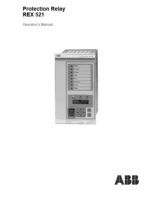
Protection Relay REX 521Operator’s Manual3REX 521Issued:29.11.2001Version:E/04.06.2004We reserve the right to change data without prior notice.Protection Relay Operator’s Manual Contents1.About this manual (5)1.1.Copyrights .....................................................................................51.2.Trademarks ...................................................................................51.3.General .........................................................................................51.4.Abbrevitations ...............................................................................61.5.Related documents .......................................................................61.6.Document revisions .. (7)2.Safety information (7)3.Introduction (8)3.1.REX 521 protection relay (8)4.Instructions (9)4.1.HMI features (9)4.1.1.Push-button functions (11)4.1.2.Selecting language (12)4.1.3.Passwords (13)4.1.4.Display backlight (13)4.1.5.Display contrast (13)4.1.6.Display test (14)4.1.7.Selecting primary values (14)4.1.8.Optically isolated serial communication port (14)4.2.Menu chart (15)4.2.1.Measurement menu (16)4.2.2.Event menu (17)4.2.3.Manual control (18)4.2.3.1.Local/Remote position selection (18)4.2.3.2.Controlling breaker (19)4.2.4.Setting parameters (21)4.2.5.Setting bit masks (21)4.3.Indication messages (22)4.3.1.Protection indications (22)4.3.2.Self-supervision (23)4.3.3.Condition monitoring indication (24)4.4.LED indicators (25)4.4.1.Green indication LED (READY) (25)4.4.2.Yellow indication LED (START) (25)4.4.3.Red indication LED (TRIP) (25)4.5.Alarm LEDs (26)4.5.1.Alarm LED 1-8 (26)1MRS 751107-MUMREX 521Protection Relay1MRS 751107-MUMOperator’s Manual5.Test mode (27)5.1.I/O test (27)5.2.IRF test (27)5.3.Function block test (28)6.Index (29)41MRS 751107-MUMProtection Relay Operator’s Manual REX 52151.About this manual 1.1.Copyrights The information in this document is subject to change without notice and should not be construed as a commitment by ABB Oy. ABB Oy assumes no responsibility for any errors that may appear in this document.In no event shall ABB Oy be liable for direct, indirect, special, incidental or consequential damages of any nature or kind arising from the use of this document, nor shall ABB Oy be liable for incidental or consequential damages arising from use of any software or hardware described in this document.This document and parts thereof must not be reproduced or copied without written permission from ABB Oy, and the contents thereof must not be imparted to a third party nor used for any unauthorized purpose.The software or hardware described in this document is furnished under a license and may be used, copied, or disclosed only in accordance with the terms of such license.Copyright © 2004 ABB Oy All rights reserved.1.2.Trademarks Brand and product names mentioned in this document are trademarks or registered trademarks of their respective companies.1.3.GeneralThe purpose of this manual is to provide the user with basic information on the protection relay REX 521 Revision E, and to especially focus on explaining the use of the human-machine interface (HMI).For information about the new features of the relay, refer to REX 521 Technical Reference Manual, General (see “Related documents” on page 6).61MRS 751107-MUM Protection Relay Operator’s Manual REX 5211.4.Abbrevitations 1.5.Related documents Manuals for the REX 521Parameter and event lists for the REX 521Tool-specific manuals CBFP Circuit-breaker failure protection CT Current transformer HMI Human-machine interface HSPO High-speed power output IRF Internal relay fault LCD Liquid chrystal display PO Power output RS Rogowski sensor SO Signalling output VD Voltage divider VT Voltage transformer •Technical Reference Manual, Standard Configurations 1MRS 751802-MUM •Technical Reference Manual, General 1MRS 751108-MUM •Installation Manual 1MRS 750526-MUM •Technical Descriptions of Functions (CD-ROM)1MRS 750889-MCD •Modbus Remote Communication Protocol for REX 521, Technical Description 1MRS 755017•DNP 3.0 Remote Communication Protocol for REF 54_ and REX 521, Technical Description 1MRS 755260•Parameter List for REX 5211MRS 751999-RTI •Event List for REX 5211MRS 752000-RTI •General Parameters for REX 5211MRS 752156-RTI •Interoperability List for REX 5211MRS 752157-RTI •CAP505 Installation and Commissioning Manual 1MRS 751273-MEN •CAP505 Operator’s Manual 1MRS 751709-MEN •CAP505 Protocol Mapping Tool, Operator’s Manual 1MRS 755277•Tools for Relays and Terminals, User’s Guide 1MRS 752008-MUM •CAP 501 Installation and Commissioning Manual 1MRS 751270-MEN •CAP 501 Operator’s Manual 1MRS 751271-MUM1MRS 751107-MUMProtection Relay Operator’s Manual REX 52171.6.Document revisions 1.7.Safety information Version Revision number Date History D 25.03.2004Document layout changed E 04.06.2004Pictures updated in tables, chapter 3.2.1.Changes in tables, chapters 3.4.1. and 3.5.1.Warning text added, chapter 4.1.REX 521Protection Relay1MRS 751107-MUMOperator’s Manual2. Introduction2.1.REX 521 protection relayThe protection relay REX 521 is designed for protection, control, measuring andsupervision in medium voltage networks. Typical applications include incoming andoutgoing feeders as well as substation protection. The protection relay is providedwith energizing inputs for conventional current and voltage transformers. Also ahardware version with inputs for current and voltage sensors is available.The protection relay is based on a multiprocessor environment. The HMI includingan LCD (liquid chrystal display) with different views makes the local use easy andinforms the user via indication messages. Modern technology is applied both inhardware and software solutions.The REX 521 is part of the substation automation concept for distributionautomation and extends the functionality and flexibility of the concept.81MRS 751107-MUM Protection RelayOperator’s Manual REX 52193. Instructions3.1.HMI features•Push-buttons for navigating, [C] Clear/Cancel and [E] Enter •Language selection•Setting values are protected by passwords•Display backlight•Display contrast•Display test•Selection of primary values•Optically isolated serial communication port•Three LED indicators•Eight programmable alarm LEDsREX 521Protection Relay1MRS 751107-MUMOperator’s Manual ArrayFig. 3.1.-1HMI front view1.Alarm LEDs2.LED indicator: Trip, CBFP3.LED indicator: Start, Block4.LED indicator: Ready, IRF, Test mode5.LCD6.Optical PC connector7.Navigation buttons8.Clear/Cancel9.Enter103.1.1.Push-button functionsThe HMI includes push-buttons for operating the protection relay.A quick touch on the arrow button up [↑] or down [↓] is interpreted as one stepupwards or downwards in a menu or as the minimum step up or down in settingmode of a parameter.•The cursor stops at the first and last rows in a menu; pressing the [↑] button at thefirst row or [↓] button in the last row is ignored.•If the [↑] or [↓] button is kept pressed, the menus are automatically scrolled fasterthan with single button pressings.Fig. 3.1.1.-1Push-buttonsThe table below gives a short explanation of the push-buttons and their functions.Table 3.1.1-1Push-button functions11Table 3.1.1-1Push-button functions3.1.2.Selecting languageFig. 3.1.2.-1Selecting language1.Select with [↓] and [→ ] buttons Configuration in the main menu,General in the group menu, Software in the subgroup menu andActive language in the parameter menu.2.Press the [E] button until the second row of the display starts flashing. Thenselect the desired language with [↓] and [↑] buttons.3.Confirm the selection by pressing the [E] button once more or cancel theselection by pressing the [C] button.After altering the language, the display menus are shown in the new language andthe selection is restored after a disconnection of the power supply.12Operator’s Manual3.1.3.PasswordsFig. 3.1.3.-1Password menusSetting values are protected by passwords. There are two different passwords, onefor protecting the HMI setting values and another for protecting settings throughserial communication.•The default value of the serial communication password is 001 and of the HMIpassword 999.•The HMI password is not active until it has been changed from the default value.After changing it, the relay prompts for password whenever the [E] button ispressed in the setting value menu. Once the right password has been given, itstays active until the display is returned to idle state by time-out. To disable theHMI password, change it back to the default value 999.•In case a password is forgotten, the HMI password can be viewed and changedvia serial communication.3.1.4.Display backlightThe backlight of the display is normally off. When a button on the HMI is pressed,the backlight turns on automatically and the panel is ready for further operations.•At power up, the backlight is also turned on during the display test.•After a time-out period (5 min), the backlight is automatically switched off ifthere has not been any activity on the panel.•When changing between Local/Remote mode by a digital input, the backlight isturned on for 10 seconds.3.1.5.Display contrastThe display contrast is temperature compensated, which means that the contrastautomatically adjusts itself with temperature to preserve readability.•To obtain optimal readability, the contrast of the display can be adjusted.Pressing simultaneously the [E] button and [↑] or [↓] button increases ordecreases the contrast.13Fig. 3.1.5.-1Adjusting display contrast•The display contrast may be adjusted anywhere in the menu structure except inthe setting menus where the [E] button is used for entering the setting mode.•The selected contrast value is stored in a non-volatile memory and thus, after anauxiliary power failure, the contrast is restored automatically.3.1.6.Display testUpon auxiliary voltage connection, the backlight is turned on and a short display testis run. This display test includes all the LEDs and the LCD. The LEDs are tested byturning them on simultaneously while the LCD shows two patterns so that all thepixels are activated. After the test, the display returns to normal state.•The display test can also be started manually by navigating toConfiguration\Display\Test display and then selectingTest display (refer to section “Menu chart” on page15).3.1.7.Selecting primary valuesThe setting values, input data and recorded values that are relative to some quantitycan be obtained directly in amperes and volts. For the relay to know how to convertbetween primary and per unit values, the setting values describing the measurementdevices (CT, VT, VD, RS) need to be properly set.1.Navigate to Configuration\Display\Primary values and selectPrimary values instead of the default Per unit values.2.Navigate to Configuration\Meas. devices and enter the data for allthe CTs and VTs, VDs and RSs that are in use in that particular hardware. Forinformation about setting the rated values for the protected unit and about thetechnical data of the measuring devices, refer to Technical Reference Manual,General (see “Related documents” on page6).3.1.8.Optically isolated serial communication portThe front panel of the protection relay is provided with an optical serialcommunication connector. The connector is used for programming the relay with aPC via a RS-232 cable, type 1MKC950001-1.143.2.Menu chartThe contents of the menu chart depend on the configuration of the relay. However,Fig. 3.2.-1An example of a menu chart structure15Operator’s Manual3.2.1.Measurement menuThe contents of the measurement menu depend on the relay configuration.If a measurement view is selected, it remains active after the time-out period. Thesame is true with the manual control view. From other views, the display reverts toidle mode at the same time as the backlight is switched off.•If energy measurements are present, accumulated values can be reset by pressingthe [C] button for 2 s.Table 3.2.1-1Measurement view16Table 3.2.1-1Measurement view (Continued)* The calculated thermal level of the device, maximum from the stator and the rotor.**Only available in configuration H083.2.2.Event menuThe event menu (Main menu\Measured values\Events) contains thefunction block name and the event in the same manner as the indication messages(see “Indication messages” on page22). The first view of the event menu shows theamount of events (maximum 50). The most recent event is stored on top of the list.When a certain event is selected, date and time of the event in question can be readby moving one step right with the [→ ] button. If the event in question is a trip eventand its data in the recorded data menu (Main menu\Protection\…\Recorded data1\…3\) has not been overwritten, it is possible to move directlyto the associated recorded data by moving right [→ ] again in the date and time view.Return to the event view with the [C] button or with the [← ] button, like in normalmenu navigation. When viewing recorded data, the return is directed to the eventsummary view (Main menu\Measured values\Events) if•the recorded data is overwritten, or•the original event is overwritten in the event list, or•the event list is cleared.These events are stored in the non-volatile memory, which means that they can alsebe seen after a disconnection of the power supply. When displayed, the event list canbe cleared by pressing the [C] button for 2 seconds.17Fig. 3.2.2.-1Event view3.2.3.Manual control3.2.3.1.Local/Remote position selectionThe control position can be changed in Control\Manual control\Local/Remote.•The control mode can be selected by pressing the [E] button and using the [↑] and[↓] buttons.•The [E] button confirms the selected mode and the [C] button cancels theselection and keeps the current mode.For password handling, refer to section “Passwords” on page13.Table 3.2.3.1-1Control positionsControl position DescriptionControl off Local and remote operations are inhibited. The current state of the objectis shown in the control menu.Local Object can be controlled from the HMI and the digital inputs. Remotecontrol is inhibited.Remote Object can be controlled via remote communication. Control from theHMI and digital inputs is inhibited and the object state is shown in thecontrol menu.External input The digital input programmed for selector Local/Remote is used forselecting between the local and remote modes. When selected the modewill be displayed as Local (ext.) or Remote (ext.) depending onthe digital input state.The selected control position remains the same during auxiliary power-off.When the local mode is selected, the character “L” is shown in the bottom-rightcorner of the HMI main view. However, if the language in the relay is other thanEnglish, the character that is shown in the display depends on the selected language. 183.2.3.2.Controlling breakerThe object control menu is in Control\Manual control\Control CB.Only the current position of the breaker is shown and no control is possible in remoteor control off mode. In local mode the state of the breaker is shown and the possibletarget states can be scrolled with [→ ] and [← ] buttons. Possible target states areopen and closed. When the desired target state is selected the object can be selectedby using the [E] button.Message =Preparing... can be briefly shown before the text=Are you sure? is displayed. The operation can then be confirmed with the [E]button and cancelled with the [C] button. If the operation is cancelled the text=Aborted is displayed for three seconds and then the current state of the breakeris shown. The same happens if the =Are you sure? has been displayed for 30seconds.Notice that an adjustable timeout in Control\General\Select timeoutrestricts the time between the object selection and the control request. If the timeoutis shorter than 30 seconds and it elapses before the operation is confirmed,controlling the object will not be possible before the object is selected again. If theoperation is confirmed, the appropriate transition text (=Opening... or=Closing...) is shown for at least four seconds after which the current state ofthe object is shown.19The current state of the interlocking of the object can prevent the select or executerequests. In that case the text =Interlocked is displayed for three seconds. Theattempted operation is cancelled and after the three seconds the current state of theC o n t r o l C B=O p e n. E=C l o s e=C l o s e d. E=O p e n=C l o s e d. E=C l o s eC o n t r o l C BC o n t r o l C Br e Y o u S u r e ?C o n t r o l C B=O p e n i n g ...Fig. 3.2.3.-1Manual controlTable 3.2.3-1Manual control messagesMessage MeaningAborted The current operation was aborted either by user or state change in object statusor timeout.Are you sure?Waiting for confirmation for the selected operation. [E] accepts it and [C] cancels it.Closed Object state is closed. Control is not possible due to remote or control off state.Closed. E=Close Object state is closed. [E] will close it.Closed. E=Open Object state is closed. [E] will open it.Closing...Object is being closed.External change Local/remote state controlled by digital inputs has changed. Only in external inputmode. Cancels current operation if any.Failed Executing the control request failed. The reason was not interlocking.Interlocked Selecting the object or executing the control request failed due to interlocking.Not allowed Selecting the object failed. The reason was not interlocking.Not local Attempted to control the object in remote or control off state.Open Object state is open. Control is not possible due to remote or control off state.Open. E=Close Object state is open. [E] will close it.Open. E=Open Object state is open. [E] will open it.Opening...Object is being opened.Preparing...Object is being selected.Undefined Object state is undefined. Control is not possible.Unresolved Object state is unknown.20Operator’s Manual 213.2.4.Setting parameters The setting parameters are listed in the CD-ROM Technical Descriptions of Functions (see “Related documents” on page 6).1.Navigate to the right parameter using the buttons [↑], [↓] and [→ ], [← ] and the menu chart structure as reference.2.Activate setting mode by pressing the [E] button.3.If the default HMI password has been changed, it is now prompted. To enter the valid password, change the active digit by pressing the buttons [← ] and [→ ], then set the digit value by pressing the buttons [↑] and [↓].4.Once the password has been entered, press the [E] button to confirm. Now the selected setting value starts flashing.5.Enter the new setting value using the buttons [↑], [↓] and [→ ], [←].6.Press the [E] button to confirm.7.If the new value is within the allowed limits, it is now stored in the non-volatile memory and restored after disconnection of power supply.8.If an illegal setting value is confirmed, a message in the display tells the user that the setting is out of range by showing the message Invalid value, and the previous parameter value remains unchanged.3.2.5.Setting bit masksEvent masks and switchgroups are presented as bit masks with a checksum. Most of the events can be included in or excluded from the event reporting by altering the bits of the event masks. Switchgroups are used for changing the connections of inputs and outputs to the relay function blocks.Fig. 3.2.5.-1Bit mask in setting modeWhen navigating in menus containing bit masks, only the checksum is shown. If setting mode is entered, the single bit presentation (bit 0, value 1, in the example above) appears in the rightmost lower corner of the display. The contents of the bit mask may be altered by entering single bit values. However, the new values are not valid until setting mode has been exited by pressing the [E] button.1.Navigate to the right parameter using the buttons [↑], [↓] and [→], [← ] and the menu chart structure as reference.2.Activate setting mode by pressing the [E] button.3.If the default HMI password has been changed, it is now prompted. To enter the valid password, change the active digit by pressing the buttons [← ] and [→ ], then set the digit value by pressing the buttons [↑] and [↓].4.Once the password has been entered, press the [E] button to confirm. Now the selected setting value starts flashing.5.Enter the new setting value using the buttons [↑], [↓] and [→ ], [← ].6.Press the [E] button to confirm.When entering single bit values, the bit to be edited may be shifted by pressing the[→ ] button when the cursor is located in the rightmost corner of the display. In thatway, the cursor does not have to be moved back and forth between the bit numberand the value during the setting period, thus simplifying the procedure.For information about the meaning of each event, refer to Event List for REX 521on the CD-ROM Technical Descriptions of Functions (see “Related documents” onpage6).3.3.Indication messagesThere are two different kinds of indication messages:•A text message together with a LED indication.This type of messages are related to information from the protection functionsand information concerning the condition of the protection relay (self-supervision).•A text message without a LED indication.This type of messages are related to condition monitoring, alarms and warningsor help texts appearing when certain display operations are performed.Indication messages have a certain priority. If different types of indications occursimultaneously, the message with the highest priority appears on the display.Priority order of the messages:1.Internal fault, CBFP2.Trip3.Start, Block4.Help messagesIndication messages may be cleared with the [C] button, until the display reverts tothe menu active before the events.Help messages are displayed when certain operations are done. For example, whenresetting output relays, events and registered values by pressing the [C] and [E]buttons for 5 s, a help text describing the operation is displayed at the same time.3.3.1.Protection indicationsWhen a protection function starts, the symbol of the protection function and the textSTART are displayed. The corresponding yellow LED indicator is also lit. In caseof three-phase or two-phase protection functions, the faulted phases are displayed aswell.Fig. 3.3.1.-1Indication of startIf a started protection function is blocked, the name of the function and the textBLOCK are displayed. Now, the yellow LED indicator is blinking.22Fig. 3.3.1.-2Indication of blockingIf a protection function trips, the name of the function and the text TRIP appear onthe display. The red LED indicator is lit. The faulted phases are displayed in thiscase.Should the protection function deliver a delayed trip for circuit-breaker failureprotection (CBFP), the red indicator starts blinking.Fig. 3.3.1.-3Indication of trip3.3.2.Self-supervisionThe protection relay is provided with an extensive self-supervision system. The self-supervision system handles run-time fault situations and informs the user aboutexisting faults over the display and the serial communication.When a fault has been detected, the green READY indicator starts blinking. At thesame time, the self-supervision (IRF) output relay is activated.Additionally, a fault indication text INTERNAL FAULT appears on the display andan event is generated.Fig. 3.3.2.-1Indication of faultThe fault indication has the highest priority and no other indication can overrun it.The fault indication text is displayed until it is cleared by pressing the [C] button.The green READY indicator continues blinking as long as the fault is present.Should the fault disappear after a reset, the indicator stops blinking and an event isgenerated over the serial communication. The self-supervision (IRF) output relay isreturned to its normal state.23243.3.3.Condition monitoring indicationIf the relay configuration includes condition monitoring functions that are not directly related to any protection function or to the internal relay condition,indication messages with the message SUPERV and an explanatory text appear if faults are found.Fig. 3.3.3.-1Condition monitoring indicationOperator’s Manual3.4.LED indicators3.4.1.Green indication LED (READY)3.4.2.Yellow indication LED (START)3.4.3.Red indication LED (TRIP)253.5.Alarm LEDs3.5.1.Alarm LED 1-8a.Valid only if the LED is not activated by the parameter Alarm LED States.b.The alarm can also be OFF if an auxiliary supply break has occurred. The state of the LED is thenpreserved and has to be acknowledged (cleared) from the main view.26274. Test modeDigital inputs, output relays and IRF relay may be tested by setting the parameter Test mode to Testing in the menu Main menu\Tests\General . When test mode is activated, the green READY indicator is blinking. For more information, refer to Technical Reference Manual, General (see “Related documents” on page 6).Test mode can be cancelled by setting the parameter to No test or by disconnecting the power supply.If the user does not cancel the test mode, it remains active and the Ready LED remains blinking.4.1.I/O test The picture below shows the menu used for digital input testing (Tests\Inputs ) in the hardware variant with nine digital inputs. The digits correspond to the inputs DI1...DI9, starting from the right side. Fig. 4.1.-1Digital input testing The following picture shows the menu used for output relay testing Tests\Outputs . Observe that the self-supervision relay is activated in another menu and is thus not included in this menu. The relays are activated in the order: SO, PO and HSPO, starting from the right side.Fig. 4.1.-2Output relay testing If the user forgets to cancel the test mode, it remains on and the Ready LED indicator remains flashing.4.2.IRF testThe IRF relay may be tested by activating the IRF relay in the menuMain menu\Tests\General\Activate IRF .4.3.Function block testThe outputs (Start and Trip) of a function block can be activated locally via the HMIor externally via serial communication. This is possible without setting the relay intest mode as described in “Test mode” on page27. The outputs are activated byusing control parameters of the function. For more information about the functions,refer to the CD-ROM Technical Descriptions of Functions (see “Related documents”on page6).285. IndexAAbout this manual (5)Alarm LEDs ..........................................................................................9, 261-8 (26)Modes (26)BBit masks (21)Altering contents (21)Breaker (19)Buttons (11)DDigital inputsTesting (27)DisplayAdjusting Contrast (13)Backlight (13)Contrast (13)Display test (14)Language (12)EEvent view (17)HH07 configurationMeasurement view (17)HMI features (9)IIndication messagesCondition monitoring (24)Green LED (25)Help messages (22)Internal fault (22)Protection indication (22)Self-supervision (23)Start, Block (22)Trip, CBFP (22)Introduction (8)IRF relayTesting (27)JJump (17)29。


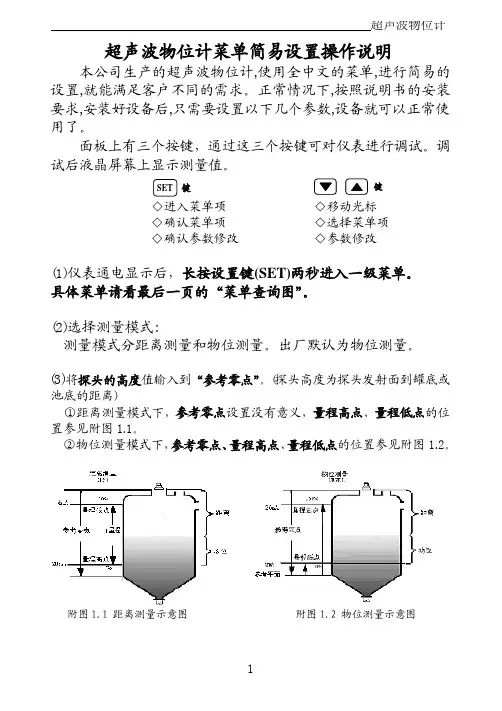
S500 系列大屏幕温湿度计用户手册S500 系列温湿度记录仪用户手册S500-EX/TH/ET/DT-USB S500-EX/TH/ET/DT-RS4854.1 注意事项----------------------------------------------------------------------------------------------------4.2 常见故障----------------------------------------------------------------------------------------------------目 录第一章 产品介绍-------------------------------------------------------------------------11.1 产品特点----------------------------------------------------------------------------------------------------1.2 使用范围----------------------------------------------------------------------------------------------------1.3 性能参数----------------------------------------------------------------------------------------------------1.4 S500-EX/TH/ET/DT-USB记录仪外型说明------------------------------------------------------------1.5 S500-EX/TH/ET/DT-RS485记录仪外型说明--------------------------------------------------------- 1.6 LCD 显示屏符号说明-------------------------------------------------------------------------------------1.7 按键功能说明----------------------------------------------------------------------------------------------第二章 S500-EX/TH/ET/DT-USB软件使用指南-------------------------------------2.1 USB 驱动安装----------------------------------------------------------------------------------------------2.2 Logpro 软件的使用---------------------------------------------------------------------------------------第三章 S500-EX/TH/ET/DT-RS485软件使用指南----------------------------------3.1 ToMonitor 实时监测软件的使用方法-----------------------------------------------------------------3.2 查看上传的数据-------------------------------------------------------------------------------------------第四章 使用注意事项-------------------------------------------------------------------------------111234557510131616516第一章 产品介绍1.1 产品特点1.2 使用范围采用进口原厂封装校准一体式温湿度传感器内置容量存储器,可存储4.3万组温湿度数据测量温湿度精准度高温湿度数据和时间同时显示,按键操作简单方便内置声光报警,超限报警功能。
REX 521 保护继电器操作手册1MRS 751107-MUM REX 521操作手册出版时间:27.6.2001版本: B/15.10.2001ABB保留对数据的修改权---------------------------------------------------------------------------------------------目录1. 简介 (4)1.1. REX 521 保护继电器 (4)2. 使用须知 (5)3.操作指导 (6)3.1. 人机界面HMI 特点 (6)3.1.1. 按钮介绍 (6)3.1.2. 选择语言 (7)3.1.3. 密码 (8)3.1.4. 显示背景荧光 (8)3.1.5. 显示对比度 (9)3.1.6. 显示试验 (9)3.1.7. 选择一次侧数值 (9)3.1.8. 光隔离的串行通行口 (9)3.2. 菜单图解 (10)3.2.1. 测量菜单 (11)3.2.2. 事件菜单 (11)3.2.3. 整定参数 (12)3.2.4. 整定数据位 (12)3.3. 提示信息 (13)3.3.1. 保护指示 (13)3.3.2. 自检 (14)3.3.3. 状态监视指示 (14)3.4. LED 指示灯 (15)3.4.1. 绿色指示灯LED (READY) (15)3.4.2. 黄色指示灯LED (START) (15)3.4.3. 红色指示灯LED (TRIP) (16)4. 服务 (17)4.1. 试验模式 (17)4.1.1. I/O 试验 (17)5. 参考资料目录 (18)1. 简介本手册向用户提供REX521继电器的基本情况,重点说明人机界面(HMI)的使用。
1.1. REX 521 保护继电器REX521继电器可用于中压电网的保护,控制,测量和监视。
主要用于进出线保护及变电站保护。
继电器有大容量的输入端,可以和传统的流变和压变配合使用,采用多处理器提高其性能,由强大的CPU支持的数字信号处理提高了继电器的响应时间和精度。

序 言尊敬的用户:您好!感谢您选购全新的优利德仪表,为了正确的使用本仪表,请您在本仪表使用之前仔细阅读本说明书全文,特别有关“安全注意事项”的部分。
如果您已经阅读完本说明书全文,建议您将此说明书进行妥善的保管,与仪表一同放置或者放在您随时可以查阅的地方,以便在将来的使用过程中进行查阅。
目录项目 页1一、安全提示二、特性三、技术规格四、仪器外观及配件五、测量前准备六、测量方法七、保养和维修2569101017一、安全提示本说明书包括确保仪器安全使用必须遵守的注意事项和安全规则,因此使用前请务必认真阅读。
在使用本仪器之前,请阅读并理解本说明书所包括的内容。
本说明书要妥善保管,以便随时为测试作参考。
使用本仪器必须严格按照本说明书中描述测试步骤进行。
请务必详细了解本说明书中有关安全方面的内容。
一定要严格遵守相关安全规则,否则可能导致伤害事故或仪器损坏。
23的操作。
请勿在有易燃易爆的环境下测试,否则可能会产生火花引起爆炸。
当本仪器潮湿或使用者的手潮湿的时候请勿做接线动作。
请勿施加超过本仪器的容许界限或测试范围的电量。
当您正在测试时请不要打开电池盖。
4请一定不要在出现任何不正常情况的时候进行测试。
如:胶壳破裂,测试线断 裂、脱皮外露等。
请用户不要随意拆装本仪器,若需维修请与本公司售后服务部或代理处联系。
当仪器表面湿滑,请不要更换电池或打开电池门,需先用干布擦干后再进行。
若需更换电池或打开电池门,请在关机后进行。
测试前请确认测试线的连接插头都已紧密的插入相应端口内。
当仪器在很长时间不使用时,请把电池取出并放置好。
不要把本仪器暴露在极端温度和潮湿等恶劣环境中。
请用湿布或中性清洁剂去清洁本仪器,不要用磨剂或溶剂。
当本仪器潮湿时,请确定使其干燥后储存。
本仪器中图形标志有以下几种,使用时请注意其内容:表示危险、警告、注意标志 表示有双重绝缘或强化绝缘保护表示交流(AC) 接地符合欧洲共同体(European Union)标准二、特性本仪器采用智能微控制器芯片控制,具有高精度和高可靠性;可用于测量各种电力设施配线,电气设备,防雷设备等接地装置的接地电阻值,还可以进行接地电压测量。

ET2154用户手册V1.0深圳市芯海科技有限公司2004年06月11日目 录 ET2154的主要特征 (8)1.功能描述 (8)2.系统框图 (8)3.引脚定义 (10)引脚顶层图 (10)引脚描述 (10)4.寄存器映射表 (15)错误计数寄存器 (19)双极性(BPV)或编码错误(CV)计数器(VC1~2) (19)CRC错误计数器(CRCC1~2) (20)E-bit计数器(EBC1~2) (20)FAS错误计数器(FASC1~2) (21)状态及信息寄存器 (21)状态寄存器1(STATE1) (22)状态寄存器2(STATE2) (23)接收信息寄存器(RI) (23)ET2154版本寄存器(ID) (24)接收控制寄存器1(RC1) (24)接收控制寄存器2(RC2) (25)发送控制寄存器1(XC1) (26)发送控制寄存器2(XC2) (26)通用控制寄存器1(GCR1) (27)中断控制寄存器1(ICR1) (28)中断控制寄存器2(ICR2) (28)线缆接口控制寄存器(LIC) (29)通用控制寄存器2(GCR2) (30)通用控制寄存器3(GCR3) (31)Sa插入控制寄存器(XsaC) (32)同步状态寄存器(SYNCR) (32)接收非帧对位字寄存器(RNAF) (33)发送帧对位字寄存器名称(TAF) (33)发送非帧对位字寄存器(TNAF) (34)基于硬件的信令处理 (34)时钟阻塞寄存器 (35)发送时钟阻塞寄存器(XCB1~4) (35)单通道编码产生 (36)发送侧编码产生 (36)发送空闲寄存器(XI1~4) (36)发送空闲选择寄存器(XID) (37)接收时钟阻塞寄存器(RCB1~4) (37)基于双帧的内部寄存器操作 (37)接收帧对位字寄存器(RAF) (37)ET2154信令操作 (38)处理器方式信令操作 (38)接收信令寄存器(RS1~16) (38)发送信令寄存器(XS1~16) (39)CRC4复帧的内部寄存器操作 (40)发送信道控制寄存器(XC1~32) (40)接收信道控制寄存器(RC1~32) (41)发送数据插入控制寄存器(XCC1~4) (41)接收数据插入控制寄存器名(RCC1~4) (41)通用控制寄存器4(GCR4) (42)DS0监控寄存器 (42)发送端DS0监控寄存器(XDS0) (43)接收端DS0监控寄存器(RDS0) (43)通用控制寄存器5(GCR5) (43)弹存操作 (44)接收侧弹存操作 (44)发送侧弹存操作 (44)S A及S I比特操作 (44)Sa及Si比特操作硬件模式 (45)5.线路接口电路功能 (45)接收端时钟数据恢复 (45)发送脉冲成型 (45)抖动衰减 (47)6.ET2154的环回功能描述 (48)远端环回(Remote Loopback) (48)数字本地环回(Local Loopback) (49)7.ET2154接口时序 (49)接收侧时序图 (49)接收端基本时序图 (49)接收端边界时序1(接收弹性缓存禁止) (49)接收侧2.048MHz边界时序图2(接收端弹性缓存使能) (50)接收端接口时序特性 (50)接收端管脚时序 (51)接收端系统接口详细时序图 (51)接收端LIU接口时序 (52)发送端时序 (52)发送端基本时序图 (52)发送端边界时序1(发送弹性缓存禁止) (53)发送端2.048MHz边界时序(发送弹性缓存使能) (53)ET2154工作在G.802模式下的时序图 (53)发送端时序特性参数及时序图 (54)发送端详细时序 (54)发送端系统接口时序 (55)发送端线路接口时序 (55)CPU接口时序特性及时序图 (56)数据、地址总线复用接口特性及时序图 (56)总线复用模式时,INTEL、MOTORORA读写时序图 (56)数据总线、地址总线非复用CPU接口时序特性及时序图 (57)数据总线、地址总线非复用CPU接口读写时序图 (57)8.ET2154的同步搜索流程图 (59)9.ET2154发送成帧流程图 (59)10.ET2154极限工作条件及电气特性 (61)极限工作条件 (61)ET2154电气特性 (61)安全警告 (61)11.ET2154的封装 (62)12.附录1:缩略语 (64)表格 表1 引脚描述表10 表2 寄存器映射表15 表3 双极性/编码错误计数器(VC1~2)20 表4 CRC错误计数器(CRCC1~2) 20 表5 E-BIT计数器(EBC1~2)20 表6 FAS错误计数器(FASC1~2) 21 表7 状态寄存器1(STATE1)22 表8 接收报警检测标准22 表9 状态寄存器2(STATE2)23 表10 接收信息寄存器(RI)23 表11 ET2154标志寄存器(ID)24 表12 接收控制寄存器(RC1)24 表13 同步及再同步标准25 表14 接收控制寄存器2(RC2)25 表15 发送控制寄存器1(XC1)26 表16 发送控制寄存器2(XC2)26 表17 通用控制寄存器1(GCR1)27 表18 中断控制寄存器1(ICR1)28 表19 中断控制寄存器2(ICR2)29 表20 线缆接口控制寄存器29 表21 通用控制寄存器2(GCR2)30 表22 通用控制寄存器3(GCR3)31 表23 S A插入控制寄存器(X SA C)32 表24 同步状态寄存器(SYNCR)32 表25 接收非帧对位字寄存器(RNAF)33 表26 发送帧对位字寄存器名称(TAF)33 表27 发送非帧对位字寄存器(TNAF)34 表28 发送时钟阻塞寄存器(XCB1~4)35 表29 发送空闲寄存器(XI1~4)36 表30 接收时钟阻塞寄存器(RCB1~4)37 表31 接收帧对位字寄存器(RAF)37 表32 接收信令操作寄存器(RS1~16)38 表33 发送信令操作寄存器(XS1~16)39 表34 发送信道控制寄存器(XC1~32) 40 表35 接收信道控制寄存器(RC1~RC32) 41 表36 发送数据插入控制寄存器(XCC1~4)41 表37 接收数据插入控制寄存器名(RCC1~4)41 表38 通用控制寄存器4(GCR4)42 表39 发送端DS0监控寄存器(XDS0)43 表40 接收端DS0监控寄存器(RDS0)43 表41 通用控制寄存器5(GCR5)43 表40 E1脉冲波形模板要求45 表42 LIC寄存器设置与应用对应表46表43 接收端接口时序特性参数50 表44 发送端时序特性参数表54 表45 数据、地址总线复用时接口时序参数表56 表46 数据总线、地址总线非复用CPU接口时序特性参数表57 表47 ET2154电气特性参数61图 表 图1 ET2154系统框图9 图2 ET2154外部引脚的实际排列时序10 图3 输出波形模板46 图4 ET2154外部连接图46 图5 ET2154抖动衰减容限47 图6 抖动衰减性能47 图7 ET2154远端环回图48 图8 ET2154帧环回图48 图9 ET2154本地环回图49 图10 接收端时序图49 图11 接收端边界时序图1(接收侧弹存禁止)50 图13 接收端详细时序图51 图14 接收端系统接口详细时序图52 图15 接收端LIU接口详细时序图52 图16 发送端基本时序图52 图17 发送端边界时序1(发送端弹性缓存禁止)53 图18 发送端2.048MH Z边界时序图(发送弹性缓存使能)53 图19 ET2154工作在G.802模式时的时序图54 图20 发送端详细基本时序55 图21 发送端系统接口详细时序55 图22 发送端LIU接口时序55 图23 INTEL总线读时序(BTS=0/MUX=1)56 图24 INTEL总线写时序(BTS=0/MUX=1)57 图25 MOTOROLA总线时序(BTS=1/MUX=1)57 图26 INTEL总线读时序58 图27 INTEL总线写时序58 图28 MOTOROLA总线读时序58 图29 MOTOROLA总线写时序58 图30 ET2154接收同步过程图59 图31 ET2154发送数据流程图61 图30 封装尺寸图62ET2154用户手册 ET2154的主要特征 ET2154是一路的E1 PCM-30/ISDN-PRI收发器,集成时钟/数据恢复及发送E1脉冲成型的片内线路接口单元(LIU)及E1帧处理器(Framer)。


OWONHDS2062M手持式数字存储示波表用户手册OWON数字存储示波表有限保修及义务范围在正常使用与维修情况下,OWON保证每一个产品无质地及工艺问题。
自发货之日算起,示波表保修期为三年,附件保修期为一年。
零配件及产品修理与维护的保修期为90天。
此保修只限于原始购买和OWON指定经销商的产品使用,客户保修不适用于保险丝和普通电池,亦不适用于任何OWON认为因错误使用、改装、疏忽或因事故或非正常条件下操作或处置而导致损坏之产品。
在90天内,OWON保证软件运转符合功能规范,且保证软件正确录制于完好无损的介质上。
OWON不保证软件毫无差错或无操作中断情况。
OWON指定经销商只能向客户对新的和未使用过的产品提供保修,而无权以OWON 名义扩充或更改保修内容。
以OWON指定的销售渠道购买的产品或按相应国际价格购买的产品可以得到保修。
当产品在一个国家购买而要送到另外一个国家去修理时,OWON保留收取修理/更换零件的权利。
对于在保修期内将有故障的产品送回维修中心,要求按原价退款、免费修理或更换,OWON的保修义务是有限的。
在需要获得保修服务时,请与就近的OWON指定的维修中心联系,或在附上故障说明、邮费及预付保险(目的地交货价)后,将产品寄往就近的OWON指定的维修中心。
对于运输中可能出现的损坏情况,OWON不承担任何风险。
产品维修后,将寄回给客户,邮费预付(目的地交货价)。
如果OWON认为出现故障的原因是由于错误使用、改装、事故或非正常情况下使用或操作,OWON将提供维修的估价并在得到认可后才进行维修。
维修后,产品在由OWON预付邮费后寄回给客户,客户须支付维修和运输费用(起运点交货价)。
此保修是买方唯一的索取补偿的权益。
在多种其它明示或默示保修,包括但不只限于那些为推销产品或与特殊目的相配合的默示的保证,同时存在的情况下,应以此保修为准。
对于在违反保修条例、合同、条约、承诺或任何其它条文时发生的例外的、间接的、偶然的及随之引起的损坏或损失,其中包括数据的遗失,OWON不承担任何责任。
ET521A示波表快速修家电实例使用ET521快四个月了,其中的方便之处不下少数,还是用几个维修实例来向大家说明一下吧。
实例1:一用户报修有一台夏普33RX10J,故障现象为有伴音,有光栅无图像。
上门开机检查,故障与用户说的一样,该用户使用的是有线电视加机顶盒通过视频接口进行收看,于是取下机顶盒视频插头用另一台电视机上正常使用的DVD的视频信号输入到该电视机上故障现象一样。
于是排除机外视频信号引起故障可能。
后改用电视机本身的射频输入,接收有线信号同样是有声音无图像。
屏幕有相关的字符显示。
证实故障在电视机本身,于是开机检查。
根据前面的试机可以说明故障原因应该在图像处理的公共部分,即A V转换及其以后的部分。
该机的AV转换IC451采用TA1218AN,通过I2C总线选择送往解码的是哪一路外部视频信号或本机的TV信号。
解N801采用IX2915CE,主图像信号由IC451通过内部选择后由38脚输出通过C401耦合的至Q401放大后C403耦合通过15脚送入XI2915CE内部。
由N801内部通过I2C 总线控制与来自33-35脚的画中画信号混合后由41~43脚输出RGB基信号,送往末级视频放大电路。
相关电路如图1所示。
图1于是将第一检测点选择在解码电路的视频Y信号输入点,测量Q401的直流工作点正常。
N801的15脚电压为2.76v与图纸标注2.7v一样。
于是改用ET521自带的示波器功能,清楚第测量到视频信号如图2所示,由此可以判断视频信号已经通过15脚送入N801的内部。
故障应该与N801及其相关电路有关。
图2有伴音黑屏还有可能与行逆程脉冲有关。
该机的行逆程脉冲是由行输出变压器的4脚通过R640后输入到N801的25脚的。
用ET521测量N801的25脚有如图3所示的行逆程脉冲输入。
说明逆程脉冲也没有问题。
图3此时想到该机具有画中画功能,于是用遥控器打开画中画,屏幕上有画中画的频道号显示,但也没有画面出现。
DS1052E型数字示波器使用说明概述DS1052E型示波器以优异的技术指标及众多功能特性的完美结合,向用户提供了简单而功能明晰的前面板,以进行所有的基本操作。
各通道的标度和位置旋钮提供了直观的操作,完全符合传统仪器的使用习惯,用户不必花大量的时间去学习和熟悉示波器的操作,即可熟练使用。
为加速调整,便于测量,用户可直接按AUTO键,立即获得适合的波形显现和档位设置。
除易于使用之外,示波器还具有更快完成测量任务所需要的高性能指标和强大功能。
通过1GSa/s的实时采样和25GSa/s的等效采样,可在示波器上观察更快的信号。
强大的触发和分析能力使其易于捕获和分析波形。
清晰的液晶显示和数学运算功能,便于用户更快更清晰地观察和分析信号问题。
技术性能双模拟通道,每通道带宽:50MHz。
高清晰彩色液晶显示系统:320×234分辨率。
支持即插即用闪存式USB存储设备以及USB接口打印机,并可通过USB存储设备进行软件升级。
模拟通道的波形亮度可调。
自动波形、状态设置( AUTO )。
波形、设置、CSV和位图文件存储以及波形和设置再现。
精细的延迟扫描功能,轻易兼顾波形细节与概貌。
自动测量20种波形参数。
自动光标跟踪测量功能。
独特的波形录制和回放功能。
内嵌FFT。
实用的数字滤波器,包含LPF,HPF,BPF,BRF。
Pass/Fail检测功能,光电隔离的Pass/Fail输出端口。
多重波形数学运算功能。
独一无二的可变触发灵敏度,适应不同场合下特殊测量要求。
多国语言菜单显示。
弹出式菜单显示,用户操作更方便、直观。
中英文帮助信息显示及支持中英文输入。
第一章示波器的初步操作说明DS1052E示波器向用户提供简单而功能明晰的前面板,以进行基本的操作。
面板上包括旋钮和功能按键。
显示屏右侧的一列5个灰色按键为菜单操作键(自上而下定义为1号至5号)。
通过它们,您可以设置当前菜单的不同选项;其它按键为功能键,通过它们,您可以进入不同的功能菜单或直接获得特定的功能应用。
SHS1000 Series Handheld Digital OscilloscopeWWW.SIGLENT .COMIntroductionSHS1000 series are dual isolated channel handhold oscilloscopes with patent IsolatedChannel technology. SHS1000 series integrate functions as Oscilloscope, Multimeter and Recorder.SHS1000 Series provides isolation from ground and isolation between channels allowing you to take floating measurements without worrying about damaging circuitry. 100 MHz Bandwidths, 1GS/s real-time sampling per channel, up to 50GSa/s equivalent sampling rate, 2Mpts memory depth. Support Scope TrendPlot, Meter TrendPlot and Scope Waveform Record, record length up to 7Mpts. 5.7 inch TFT color LCD display. Support USB storage and internal memory. Battery included, handhold available, convenient for outdoor measurement.Applications• Power electronics test, such as Switch mode power supply, Inverter, Converter and Lighting electronics.• Wind power, PV power and other new energy equipment test• Automotive electronic, electric vehicles test • Industrial Power systems strong power test • Electrical industrial site commissioning and test • Field test• Applications from microelectronic circuits to power electronics, in fields floating measurements or locale site measurements needed • EducationFeatures & BenefitsSHS1000 Series have 2 channels; provide functions asOscilloscope, Multimeter and Recorder (TrendPlot and waveform Recorder).SHS1000 Series with patent isolated channel technology provide isolation from ground and isolation between channelsCATII1000V and CATIII600V between two channels references,between channels reference and earth groundCATII600V and CATIII300V between channels reference and Multimeter input reference CATII300V and CATIII150V input directCATII1000V and CATIII600V input with 10:1 probe 5.7 inch TFT color LCD display100MHz Bandwidth, 1GS/s real-time sampling per channel, up to 50GSa/s equivalent sampling rate, 2Mpts memory depth6000 counts Multimeter, provides measurements of DCV , ACV , DCI, ACI, Resistance, Diode, Capacitance, Continuity Support Scope TrendPlot, Meter TrendPlot and Scope RecorderAutomatic and manual trigger modesTrigger types: Edge, Pulse, Video,Slope and Alternative 32 automatic waveform measurements, 3 cursor measure modes Digital Filter functions:Low pass filter,High pass filter, Band pass filter, Band limit filterMath functions: +, - ×, ÷,FFT operations Multiple Language User InterfaceStandard setup interface: USB Device,USB Host Support USB storage and updateRechargeable battery and battery charger / line power adapter includedWWW.SIGLENT .COMSHS1000 Series Handheld Digital Oscilloscope• The SHS1000 series channels are isolated from each other; real-time sampling rate is up to 1GSa/s per channel, equivalent sampling rate up to 50GSa/s • 2Mpts memory depth• Dynamic and broad input voltage range, 5mV/div~100V/div direct input • Math functions: +, - ×, ÷,and FFT • Digital Filter functions:Low pass filter, High pass filter, Band pass filter, Band limit filter• 32 types of automatic waveform measurements,3 cursor measure modes • Automatic and manual trigger modesTrigger types: Edge, Pulse, Video,Slope and Alternative • Support EasyScopeX software• Multiple Language User Interface, support Multilingual help system onlineIsolated input,make measurements in securityHigh-performance oscilloscope• Patent IsolatedChannel technology used in SHS1000 series oscilloscopes, dual channel, and 100MHz bandwidth • CATII300V and CATIII150V maximum BNC input voltage direct, CATII1000V and CATIII600V with standard 10:1 probe • CATII1000V and CATIII600V maximum voltage between two channels references•CATII600V and CATIII300V maximum voltage between Multimeter input reference and the groundSHS1000 Series Handheld Digital OscilloscopeWWW.SIGLENT .COM32 types of measurementsLong MemoryMeter TrendPlotFFT Long MemoryScope TrendPlot • Scope TrendPlot records scope measurement data in scan mode, 800K points capacity, more than 24 hours recording time• Meter TrendPlot records multimeter measurement data, 1.2M points recording depth, at 0.5GSa/s, recording time 8120 hours• Recording results export available, convenient for father analysis • Two kinds of display mode, ‘ALL’ and ‘NORMAL’; support zoom and cursor • Support recording real timeTrendPlotWWW.SIGLENT .COMSHS1000 Series Handheld Digital OscilloscopeACI measurementDCV measurement • Recording scope waveform continually in scan mode • Support recording, replay and zoom function • 7M points memory depth,18 hours recording time • 4GB in USB storage mode, 3000hours recording time• 6000 counts high performance Multimeter• Providing measurements of DCV , ACV , DCI, ACI, Resistance, Diode, Capacitance, ContinuityScope RecorderMultimeterSpecificationSHS1000 Series Handheld Digital OscilloscopeNote: [1], [2] For rank A range, the measurement time should be less than 10s, the interval time should be more than 15 minutes.WWW.SIGLENT .COMSHS1000 Series Handheld Digital OscilloscopeTechnical Specifications• OscilloscopeSHS1000 Series Handheld Digital OscilloscopeWWW.SIGLENT.COMSHS1000 Series Handheld Digital Oscilloscope• Multimeter• RecorderSHS1000 Series Handheld Digital OscilloscopeWWW.SIGLENT.COMGeneric SpecificationWWW.SIGLENT .COMSHS1000 Series Handheld Digital OscilloscopeOrdering Information• SHS1000 series Handheld Digital OscilloscopeFacebook: SiglentTech。