Modeling of biased flow phenomena associated with the effects of static magnetic-field application
- 格式:pdf
- 大小:1.07 MB
- 文档页数:14

不同均相流模型均相流模型是用于描述多相流系统中的均匀性或各向同性的假设。
这种模型在物理上可以应用于流体力学、化学反应动力学和热力学等领域。
根据不同的应用场景和需求,有多种不同的均相流模型,以下是其中几种常见的模型:1.理想均相流模型理想均相流模型假设多相流系统中的各相是均匀分布的,没有相分离或聚集的现象。
各相之间的界面消失,整个系统具有均匀的物理性质。
这种模型通常适用于描述流体动力学中的均匀流动,如不可压缩的牛顿流体。
2.分子均相流模型分子均相流模型基于分子动力学理论,将多相流系统视为由分子组成,并考虑分子之间的相互作用和碰撞。
这种模型可以准确地描述微观尺度上的流动现象,如粘性、扩散和传热等。
然而,由于计算复杂度高,分子均相流模型在实际工程中的应用受到限制。
3.统计均相流模型统计均相流模型结合了分子动力学和宏观流体动力学的方法,通过引入概率密度函数来描述多相流系统中分子的分布和运动状态。
这种模型可以处理分子之间的相互作用和统计涨落效应,同时保持了宏观流体动力学的简单性和准确性。
4.连续介质均相流模型连续介质均相流模型假设多相流系统中的各相是连续分布的,没有明显的界面或颗粒。
这种模型通常适用于描述宏观尺度上的流动现象,如管道流动、涡旋等。
连续介质均相流模型可以进一步细分为无粘性流动、粘性流动和扩散流动等不同类型。
5.多尺度均相流模型多尺度均相流模型考虑了多相流系统中不同尺度的流动现象,包括微观尺度、宏观尺度和介观尺度等。
这种模型通过建立不同尺度之间的联系和转换关系,综合利用各个尺度的动力学机制,以获得更全面和准确的流动特性。
多尺度均相流模型在多相流系统的模拟和分析中具有广泛的应用前景。
这些不同的均相流模型在数学表达式、物理意义和应用范围方面存在差异。
在实际应用中,需要根据具体问题的需求选择合适的均相流模型,并进行相应的参数拟合或调整。
同时,需要注意模型的局限性,对于超出适用范围的问题,可能需要采用更复杂的数值模拟方法或实验研究手段来处理。

基底和膜层-基底系统的赝布儒斯特角计算(英文)刘华松;姜玉刚;王利栓;姜承慧;季一勤【期刊名称】《光子学报》【年(卷),期】2013(0)7【摘要】对基底和膜层-基底系统的赝布儒斯特角进行了数值计算.结果显示:当基底的消光系数小于0.01时,基底的赝布儒斯特角主要是由折射率决定;当基底的消光系数大于0.1时,基底的赝布儒斯特角不仅与折射率有关,而且还与消光系数有关,随着消光系数发生后周期性变化.研究表明:单层膜-基底系统的赝布儒斯特角主要由膜层的物理厚度、折射率、基底的光学常量所决定;在HfO2-硅和HfO2-融石英基底系统中,赝布儒斯特角随着入射光波长和膜层厚度的变化呈现准周期性规律变化,可能是由入射光在膜层的干涉效应引起的.【总页数】6页(P817-822)【关键词】光学常量;折射率;消光系数;膜层-基底系统;赝布儒斯特角【作者】刘华松;姜玉刚;王利栓;姜承慧;季一勤【作者单位】天津津航技术物理研究所天津市薄膜光学重点实验室,天津300192;同济大学物理系先进微结构材料教育部重点实验室,上海200092;哈尔滨工业大学光电子技术研究所可调谐激光技术国家级重点实验室,哈尔滨150080【正文语种】中文【中图分类】O484【相关文献】1.以介孔TiO2膜为过渡层在玻璃基底上制备Cu3(BTC)2连续膜 [J], 李力成;钱祺;王磊;仇龙云;王昊翊;张所瀛;杨祝红;李小保;赵学娟2.前列腺癌发生发展中基底细胞层和基底膜的改变 [J], 杨敏;刘爱军;韦立新;郭爱桃;宋欣;陈薇3.镍改性层增强铜基底沉积金刚石膜的形核(英文) [J], 刘学璋;魏秋平;翟豪;余志明;4.硅基底上生长金刚石层细晶粒的研究(英文) [J], 何敬晖;玄真武;刘尔凯5.在n型硅基底上二次注入硼离子金刚石膜的p-n结效应(英文) [J], 孙秀平;冯克成;李超;张红霞;费允杰因版权原因,仅展示原文概要,查看原文内容请购买。

分子动力学析出相分子动力学析出相是一种重要的物理理论,一般用于研究分子或原子的运动,也可以用于研究固态物质的相态。
史上,分子动力学析出相已经发挥了重要作用,因为它引发了数学、物理和其他领域的发展,并且已创造出许多新的实验结果和数据,为物理学的理论提供了一个新的方向。
第一部分:理论分子动力学析出相的基本思想是在具有一定形状的容器中,不同的原子和分子以一定的动能形式移动,这会导致系统的相变。
于析出相的研究,需要将稳定的时间均衡理论与瞬态研究结合起来,以求得具有实际意义的结果。
稳定时间均衡理论以Maxwell-Boltzmann分布为基础,它描述了不同动能下原子或分子的分布情况。
于这一理论,可以推算出在一定条件下,原子或分子之间在特定空间体积内的反应和分布规律。
瞬态研究是指在特定时间间隔内,原子或分子之间的反应和物质结构变化。
于这一理论,可以推算出原子或分子之间在各种条件下的相变,并以此为基础推断出适合局部相变的参数,从而可以预测整体的系统状态。
第二部分:方法为了探究分子动力学析出相的本质,必须使用有效的实验方法,并以此结果作为基础来分析和验证分子动力学析出相的理论。
前,许多实验室及研究机构都采用了以下几种实验方法来研究分子动力学析出相:(1)热力学分析法:通过热力学分析,可以确定分子析出的相的形状、尺寸、组成等,同时确定析出相的形状、尺寸、组成等参数;(2)控制变量法:可以调节温度、压力、添加剂等变量,来控制分子析出相的形状及结构;(3)系统性研究法:通过不同析出条件及析出时间、析出环境等变量,可以确定不同析出情况下的分子动力学析出相;(4)后处理法:通过对实验数据进行分析,可以获得分子析出相的相第三部分:成果经过多年的研究,分子动力学析出相已经取得了很大的成果,其中包括有关体系结构、组成、相变条件等的理论研究,也包括了对实验研究成果的验证和运用。
举例来说,根据分子动力学析出相的理论,研究人员通过实验发现,高压、高温条件下,海水中的某些离子可以凝结成“气液”的析出相。
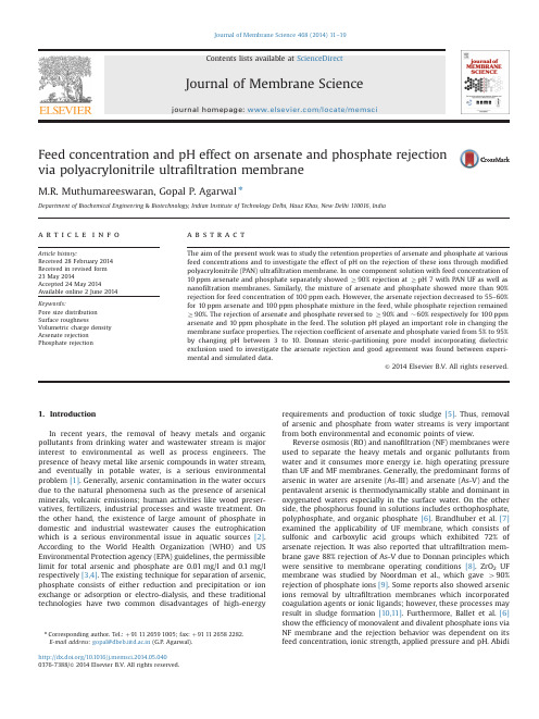
Feed concentration and pH effect on arsenate and phosphate rejectionvia polyacrylonitrile ultrafiltration membraneM.R.Muthumareeswaran,Gopal P.Agarwal nDepartment of Biochemical Engineering&Biotechnology,Indian Institute of Technology Delhi,Hauz Khas,New Delhi110016,Indiaa r t i c l e i n f oArticle history:Received28February2014Received in revised form23May2014Accepted24May2014Available online2June2014Keywords:Pore size distributionSurface roughnessVolumetric charge densityArsenate rejectionPhosphate rejectiona b s t r a c tThe aim of the present work was to study the retention properties of arsenate and phosphate at variousfeed concentrations and to investigate the effect of pH on the rejection of these ions through modifiedpolyacrylonitrile(PAN)ultrafiltration membrane.In one component solution with feed concentration of10ppm arsenate and phosphate separately showed Z90%rejection at Z pH7with PAN UF as well asnanofiltration membranes.Similarly,the mixture of arsenate and phosphate showed more than90%rejection for feed concentration of100ppm each.However,the arsenate rejection decreased to55–60%for10ppm arsenate and100ppm phosphate mixture in the feed,while phosphate rejection remainedZ90%.The rejection of arsenate and phosphate reversed to Z90%and$60%respectively for100ppmarsenate and10ppm phosphate in the feed.The solution pH played an important role in changing themembrane surface properties.The rejection coefficient of arsenate and phosphate varied from5%to95%by changing pH between3to10.Donnan steric-partitioning pore model incorporating dielectricexclusion used to investigate the arsenate rejection and good agreement was found between experi-mental and simulated data.&2014Elsevier B.V.All rights reserved.1.IntroductionIn recent years,the removal of heavy metals and organicpollutants from drinking water and wastewater stream is majorinterest to environmental as well as process engineers.Thepresence of heavy metal like arsenic compounds in water stream,and eventually in potable water,is a serious environmentalproblem[1].Generally,arsenic contamination in the water occursdue to the natural phenomena such as the presence of arsenicalminerals,volcanic emissions;human activities like wood preser-vatives,fertilizers,industrial processes and waste treatment.Onthe other hand,the existence of large amount of phosphate indomestic and industrial wastewater causes the eutrophicationwhich is a serious environmental issue in aquatic sources[2].According to the World Health Organization(WHO)and USEnvironmental Protection agency(EPA)guidelines,the permissiblelimit for total arsenic and phosphate are0.01mg/l and0.1mg/lrespectively[3,4].The existing technique for separation of arsenic,phosphate consists of either reduction and precipitation or ionexchange or adsorption or electro-dialysis,and these traditionaltechnologies have two common disadvantages of high-energyrequirements and production of toxic sludge[5].Thus,removalof arsenic and phosphate from water streams is very importantfrom both environmental and economic points of view.Reverse osmosis(RO)and nanofiltration(NF)membranes wereused to separate the heavy metals and organic pollutants fromwater and it consumes more energy i.e.high operating pressurethan UF and MF membranes.Generally,the predominant forms ofarsenic in water are arsenite(As-III)and arsenate(As-V)and thepentavalent arsenic is thermodynamically stable and dominant inoxygenated waters especially in the surface water.On the otherside,the phosphorus found in solutions includes orthophosphate,polyphosphate,and organic phosphate[6].Brandhuber et al.[7]examined the applicability of UF membrane,which consists ofsulfonic and carboxylic acid groups which exhibited72%ofarsenate rejection.It was also reported that ultrafiltration mem-brane gave88%rejection of As-V due to Donnan principles whichwere sensitive to membrane operating conditions[8].ZrO2UFmembrane was studied by Noordman et al.,which gave490%rejection of phosphate ions[9].Some reports also showed arsenicions removal by ultrafiltration membranes which incorporatedcoagulation agents or ionic ligands;however,these processes mayresult in sludge formation[10,11].Furthermore,Ballet et al.[6]show the efficiency of monovalent and divalent phosphate ions viaNF membrane and the rejection behavior was dependent on itsfeed concentration,ionic strength,applied pressure and pH.AbidiContents lists available at ScienceDirectjournal homepage:/locate/memsciJournal of Membrane Science/10.1016/j.memsci.2014.05.0400376-7388/&2014Elsevier B.V.All rightsreserved.n Corresponding author.Tel.:þ911126591005;fax:þ911126582282.E-mail address:gopal@dbeb.iitd.ac.in(G.P.Agarwal).Journal of Membrane Science468(2014)11–19et al.[12]studied the operating conditions for phosphate ions removal with NF membrane and they also reported more than93% of phosphate rejection at high pH.Polyacrylonitrile(PAN)based ultrafiltration membrane is more advantageous because of high hydrophilicity and good solvent stability.Lohokare et al.[13]show that the surface hydrolysis of PAN UF membrane using NaOH by tangential mode led to reduc-tion in pore size due to conversion of NC to COO–on the membrane surface as well as pores.It was also reported that hydrolyzed PAN membrane gave more than90%rejection of arsenic[14].Characterization and modeling of ionic solute transport through membranes are essential steps in the development and implementation of new membranefiltration processes.From the literature,most of ionic transport models of membrane were based on Spiegler–Kedem(SK)model and Donnan steric pore model(DSPM)[15,16].Thefirst was based on irreversible thermo-dynamics,which considered the membrane as a black box where driving forces for solvent and soluteflux were related to concentration and pressure gradient[17].Later,DSPM model based on extended Nernst-Planck equation wasfirst proposed by Bowen et al.[18]then,it was further improved by dielectric exclusion(DE)principle for counter ions effect on ionic solute rejection[19–21].The aim of this work was to investigate the arsenate and phosphate ions rejection through novel polyacrylonitrile(PAN) based ultrafiltration(UF)membrane as a function of feed concen-tration and pH of the solution[22].The performance of modified PAN UF membrane ionic rejection data was compared with nanofiltration membranes.DSPM-DE model was used to evaluate arsenate ion rejection as a function offlux for modified PAN UF membrane.2.Materials and methodology2.1.MaterialsRequired chemicals were of analytical grade and used without further purification.Unmodified polyacrylonitrile(PAN)mem-branes were procured from National Chemical Laboratory(NCL), Pune.Nanofiltration membranes NF200and NF99were procured from M/s.Permionics India Ltd.and M/s.Alfa Laval Corporation respectively.Sodium arsenate(Na2HAsO4Á7H2O)was procured from Loba Chemie(India);sodium phosphate(Na2HPO4Á7H2O) and methanesulfonic acid(CH4O3S)were obtained from Sigma chemicals(USA).Sodium hydroxide(1N NaOH)solution pur-chased from Merck(Germany).Deionized water with resistivity of0.055m S/cm was used in all experiments.2.2.Experimental setupA lab-scale plate and frame module(PLEIADE RAYFLOW s)had the effective membrane surface area of100cm2area procured from Orelis Environment SAS.The centrifugal pump was used to maintain the optimized crossflow velocity of0.72m/s and transmembrane pressure of200kPa,which depends on pump speed and backpressure(Fig.1).All experiments were performed by total recycle mode and feed was maintained at ambient room temperature(27–301C).During the whole operation,the volu-metricflux was determined for each samples.The pure water permeability of each membrane coupon was measured before and after completion of an experiment.The material balance of solute was carried out after completion of experiments to evaluate any absorption on the membrane.2.3.Characterization of membranesThe unmodified polyacrylonitrile ultrafiltration membranes surface were modified as per protocol described in earlier pub-lication[14].2.3.1.Atomic force microscopyEffective mean pore radius,porosity and pore size distribution of the membrane were measured by image surface analysis via atomic force microscope(AFM)made by Bruker,USA.ScanAsyst mode(peak force tapping mode:spring constant0.4N/m,reso-nant frequency40kHz)was used to analyze the samples.In addition,all samples were subjected with feed solution pH range of2–9.SPIP™(Image metrology)software(SPIP v6)used to calculate the number of pores through AFM images[23].Pore size distribution and effective mean pore radius of membrane were estimated by log normal distribution function(Eq.(1)),described by Bowen et al.[24]f RðrÞ¼1rffiffiffiffiffiffiffiffiffi2bp expÀf logðr=r nÞþb=2g2"#ð1Þwhereb¼log1:0þs nr2"#ð1:1ÞHilal et al.[25]studied the AFM images to determine the surface porosity of the membrane.To obtain the reproducibility via AFM,all samples were scanned by the same frequency and the same surface area.Porosityð%Þ¼NÂðπd2p=4ÞimageÂ100%ð2Þ2.3.2.Tangential streaming potentialElectrokinetic properties such as iso-electric point(pI)and membrane charge density(X d)were calculated by tangential streaming potential(TSP).TSP measurements were made by using the SurPASS Electrokinetic Analyzer(Anton-Paar KG,Graz,Austria) equipped with adjustable clamping cell(distance of10075m m) which had sample surface area of25Â55mm2.Background elec-trolyte of1mM KCl used to measure the zeta potential to evaluate the iso-electric point of PAN membrane at pH range of3–10. Fairbrother and Mastin(F–M)relationship(Eq.(3))was used to calculate zeta potential,because it eliminated the surface conduc-tance at low ionic strength[26].ζ¼ΔUΔpÂηεÂε0Âκð3ÞFig.1.Schematic diagram of crossflow PAN-UF membrane system.M.R.Muthumareeswaran,G.P.Agarwal/Journal of Membrane Science468(2014)11–19 12Gouy –Chapman relationship (Eq.(4))was used to determine the electrokinetic charge densities of different coupons of mod-i fied PAN UF membranes [27].s e ¼2ελd k b T ze sinh ze2k b Tð4Þwhereas,the Debye length was calculated by λd ¼ffiffiffiffiffiffiffiffiffiffiffiffiffiffiffiϵk b T4e 2N a Is ð4:1ÞIn addition,the effective volumetric charge density (X d )was assumed to be uniformly distributed in cylindrical pores and the surface area of membrane.Therefore,the effective volumetric charge density was determined by using pore radius and electro-kinetic charge densities (Eq.(5))[27]X d ¼2s e Fr pð5Þ2.4.Arsenate,phosphate and sodium ion analysisFeed,permeate and retentate samples of arsenate,phosphate and sodium were analyzed by Ion Chromatography (IC 3000)made by Dionex Ltd.,USA.Ion Pac As11HC column with 30mM NaOH solution was used to measure phosphate and arsenate ions with retention time of 5.1min and 6.6min respectively.CS12A column with 20mM methane sulfonic acid (MSA)used to measure sodium ion with the retention time of 4.3min.The rejection of arsenate,phosphate and sodium were calculated by the following equation:R ð%Þ¼1ÀC pC rÂ100ð6Þ3.Results and discussion3.1.Surface properties of PAN UF membrane3.1.1.Water fluxThree different coupons of surface modi fied PAN UF membrane were used for the measurement of flux.The average volumetric water flux of modi fied PAN UF membrane was found to be 1.770.2Â10À6m s À1at 100kPa and it was lesser than unmodi-fied PAN membranes flux (1.4Â10À5m s À1).The observed results indicated that all coupons of surface modi fied PAN UF membranes had the permeability of 2.370.2Â10À11m s À1Pa À1.In addition,the nano filtration membranes (NF 200and NF 99)pure water permeabilities were found to be 7.970.3Â10À12m s À1Pa À1and 1.870.2Â10À11m s À1Pa À1respectively.3.1.2.Pore size distributionModi fied PAN UF membrane pore size and its distribution was determined by AFM image analysis.The number of pores were arranged in ascending order by using median ranks [50%]as follows [28]:χ¼k À0:3m þ0:4 Â100ð7ÞThe obtained pore sizes were used in log normal distribution function (Eq.(1))to determine the effective mean pore radius along with standard geometrical deviation (i.e.pore size distribu-tion).In all cases,integration was performed by using the trapezium rule with a very narrow step size (0.03nm).Fig.2shows that the pore size distribution changed drastically with the function of pH.Moreover,the effective mean pore radius was found to be 0.9nm at pH Z 7.As shown in Table 1,pH Z 7,thestandard geometric deviation (s n )(or pore size distribution)was found to be less than 0.41Â10À9m with a flux of r 0.19Â10À5m s À1.Likewise,the volumetric flux (1.85Â10À5m s À1)gradually increased along with pore size distribution (0.98Â10À9m)by decreasing solution pH (up to pH 3).However,after pH 3the flux trend got reversed because of iso-electric point (pI)of the membrane i.e.,the membrane charge converted as negative to positive.In addition,the pH of solution also played an important role in image surface,which directly affected the membrane topography like roughness of the membrane surfaces.3.1.3.Membrane roughnessThe surface roughness is also one of the important properties of the membrane and it depends on the scanning area,height between sample and cantilever [29].Each AFM image was ana-lyzed by scanning the area of 700Â700nm 2and height range of 30.4nm of different portions of samples.The average roughness,root mean square roughness and average height were determined by AFM image analysis software.Fig.3shows topography of UF membrane as a function of pH of the solute.For pH 8,surface roughness (S q )was found to be 3.26Â10À9m and it gradually decreased to 1.02Â10À9m at pH 2(Table 1).From these results,it can be concluded that up to iso-electric point of membrane,the volumetric flux was directly proportional to the pore size distribu-tion and inversely proportional to the surface roughness of active layer.3.2.Arsenate and phosphate ions rejection3.2.1.Effect of feed concentrationThe modi fied PAN membrane was analyzed for various feed concentrations of arsenate (100ppm,10ppm)andphosphateFig.2.Effect of pH on pore size distribution (AFM distribution and theoretical distribution).Table 1Properties of modi fied PAN UF membrane as a function of pH.pH Roughness(S q )(Â10À9m)Pore sizedistribution (s n )(Â10À9m)Δx =A k(Â10À5m)Volumetric flux (J v )(Â10À5m/s)2 1.02 1.250.180.873 1.810.980.22 1.854 2.100.670.25 1.295 2.800.45 1.420.446 2.830.42 1.590.277 3.040.41 1.630.1983.260.321.670.15M.R.Muthumareeswaran,G.P.Agarwal /Journal of Membrane Science 468(2014)11–1913(100ppm,10ppm)at optimized operating conditions and the results were shown in Fig.4.For multicomponent system,the equal feed concentrations (100ppm)of arsenate and phosphate ions rejection were found to be Z 95%.Moreover,sodium ion rejection was also found to be more than 95%to maintain the electroneutrality condition.However,the change in proportion of feed concentration in multicomponent system like 100ppm of arsenate along with 10ppm of phosphate resulted more than 95%of As (V)but PO 42Àrejection coef ficient reduced to 55%.In addition,as per Donnan equilibrium,the sodium ion rejection was also high (Z 90%)to maintain the charge balance of the components in the solution [13].Likewise,change in proportion of As (V)at 10ppm along with 100ppm of PO 42Àgave lesser rejection of arsenate (57%)and higher rejection coef ficient of phosphate (495%)with a sodium rejection of more than 90%.This behavior was due to ionic interaction between the solutes (electrostatic interaction),molar volume and interaction between ions and membrane charge [30].3.2.2.Effect of pHThe modi fied PAN membrane was subjected with different pH conditions for arsenate and phosphate ionic rejection with opti-mized operating condition and the feed concentration of each ion as 10ppm.The variation in arsenate and phosphate along with sodium ion rejection was plotted as a function of pH as shown in Fig.5.For pH Z 7the arsenate and phosphate rejection was shown greater than 95%,whereas sodium ion was also found to be Z 95%following electroneutrality condition.In addition,the basic condi-tion,the membrane negative surface charge repulsed divalent anionic solutes such as arsenate and phosphate as per Donnan exclusion principle.For pH o 7,the rejection coef ficient of arsenate and phosphate gradually reduced as low as 3%and 6%at pH 3.3.This behavior was due to properties of arsenate and phosphate ions,whereas monovalent arsenic ðH 2AsO 4ÀÞin the pH range p K a 1¼2.2o pH o p K a 2¼7.08;HAsO 42Àin p K a 2¼7.08o pH o p K a 3¼11.5and H 2PO 4Àin p K a 1¼2.15o pH o p K a 2¼7.20;HPO 42Àdominates in p K a 2¼7.20o pH o p K a 3¼12.35[6,8].As shown in Fig.5,the iso-electric point (pI)of the membrane was found to be 3.2and the pI value also con firmed by zeta potential measurement via tangential streaming potential (TSP).Moreover,when pH moved to acidic range,the conversion of COO Àto COOH on the membrane surface was enhanced.It reduced the effective negative charge density on membrane surface and thus also the capability of membrane to repel divalent anions to cause rejection by Donnan exclusion.Beyond the iso-electric point or pH o 3,theFig.3.Topographic AFM images of modi fied PAN UF membrane studied at differentpH.Fig.4.Arsenate and phosphate ion rejection as a function feed concentration at pH 7.0;cross flow velocity of 0.72m/s;transmembrane pressure 200kPa;ambient roomtemperature.Fig.5.Arsenate (10ppm)and phosphate (10ppm)along with sodium ion rejection as a function of different pH at cross flow velocity of 0.72m/s,transmembrane pressure 200kPa,ambient room temperature.M.R.Muthumareeswaran,G.P.Agarwal /Journal of Membrane Science 468(2014)11–1914rejection coef ficient of both ions was gradually increased up to 12%at pH 2.These observations indicated that below pI value,the positively charged surface membrane repulsed positively charged solute.3.2.3.Effect of active layer thickness to membrane porosity (Δx/A k )The membrane porosity was calculated by using Eq.(2).The ratio of active layer thickness to porosity of the membrane (Δx /A k )was estimated by using Hagen –Poiseuille equation (Eq.(A6))as shown in Appendix Section A.1.The Δx /A k changed with the pH of solution and it directly affected the flux along with rejection properties of ionic solutes.The variation of rejection coef ficient and flux as a function of Δx /A k were plotted in Fig.6.It was observed that,at higher value of Δx /A k (1.6Â10À5m)the rejec-tion coef ficient of arsenate and phosphate was found to be Z 95%with a flux of 0.15Â10À5m s À1.Moreover,rejection of arsenate and phosphate decreased to 3%along with increasing flux of 1.85Â10À5m s À1at the value of (Δx /A k )0.22Â10À5m.From these observations,it was found that volumetric flux was inversely proportional to active layer thickness to porosity of the membrane (Δx /A k )and to the rejection coef ficient of ionic solutes.However,when Δx /A k was less than 0.22Â10À5m,the rejection coef ficient of ionic solutes was found to increase by 10%along with decreas-ing flux to 0.87Â10À5m s À1.This behavior was due to isoelectric point of the membrane,which was located at lower pH region (i.e.below pI,the membrane surface charge converts as positive,as described earlier).3.3.Ionic rejection through PAN UF and NF membraneThe surface modi fied PAN UF and NF membranes were used for arsenate and phosphate ion rejection by tangential mode and the results were plotted in Fig.7,as a function of time.The highest rejection of arsenate and phosphate (Z 90%)was obtained from PAN UF and NF 99membrane with a flux of 5.6Â10À6m s À1and 4.8Â10À6m s À1respectively.In addition,the anionic rejections were found to be 85%through NF 200membrane with a flux of 1.9Â10À6m s À1.This was due to intrinsic membrane properties such as poor pore size distribution and surface charge density of NF 200(result not shown here).The observed results indicated that PAN UF membrane showed better performance as compared to NF membranes.3.4.Modeling of arsenate and sodium ion rejectionThe one-dimensional Donnan steric-partitioning pore model incorporated with dielectric exclusion (DSPM-DE)was used to evaluate arsenate along with sodium ion rejection as a function of flux.The DSPM-DE model was used for charged nano filtration membrane by Bowen et al.[16].The modeling of ionic transport in PAN UF membrane was derived with the following additional assumptions:(1)the dielectric constant of the solute within the pore and effective volumetric charge density across the pores were constant;(2)concentration polarization was negligible due to dilute feed solution (low feed concentration)and high cross flow velocity.The governing equations of DSPM-DE model shown in Appendix A and the nomenclature were shown in the list of symbols.The effective volumetric charge density (X d )was calculated by electrokinetic charge density (s e )of the membrane via Fairbrother and Mastin (FM)function (Eq.(3))and Gouy Chapman relation (Eqs.(4)and (5)).Moreover,the volumetric charge density of membrane depends on feed concentration of the solute [31],thus,it was corrected by Freundlich isotherm.j X d j ¼q 12∑j z i j C 0f s ð8Þwhere q and s were the parameters of the isotherm and it was obtained by tangential streaming potential measurements.In addition,the volumetric charge density (X d )were used to evaluate dielectric constant of the solute within the pores (εp );this model,the dielectric exclusion was based on solvation energy barrier (Born model)[32].Moreover,the εp also calculated by using true rejection coef ficient data with fitting procedure [33].The model calculation of arsenate rejection based on solute and membrane parameters listed in Table 2.The volumetric charge density (X d )and dielectric constant of solute within the pore (εp )were plotted as a function of feed concentration as shown in Fig.8.For low feed concentration,X d was found to be as low as À0.2mol m À3,whereas εp was calculated as 42.3.However,the X d values increased up to À46mol m À3while εp decreased to as low as 0.5with increased solute concentration (4mol m À3).These observed results showed that the dielectric constant of solute within the pore was dependent on feed concentration of solute and inversely proportion to effective volumetric charge density of membrane.This behavior occurred due to stronger interactionofFig.6.Arsenate (10ppm)and phosphate (10ppm)ion rejection and flux (J v )as a function of active layer thickness to porosity of the membrane (Δx /A k )at cross flow velocity of 0.72m/s,transmembrane pressure 200kPa,ambient roomtemperature.parative study of NF and modi fied UF membrane for arsenate and phosphate rejections as a function of time [feed solution pH 7.0,cross flow velocity:0.72m/s,each ion feed concentration:50ppm,transmembrane pressure:250kPa,ambient room temperature].M.R.Muthumareeswaran,G.P.Agarwal /Journal of Membrane Science 468(2014)11–1915ions with water molecule,in the pores,at higher feed concentra-tion.This led to decrease the dielectric constant of solute within the pore(εp).Moreover,in this model theεp value was kept as constant as per the following equation[34]:εp¼58εbð9ÞFig.9shows that the variation of arsenate ion rejection with respect to effective volumetric charge density of membrane.The model parameters ofΔx/A k(1.63Â10À5m),effective mean pore radius r p(0.90Â10À9m)and dielectric constant within the pore εp(48.9)were used to simulate the rejection data as a function of flux.When the X d had negative charge(ZÀ0.5mol mÀ3),the arsenate ion rejection was found to be more than90%which meant that the anionic solutes were repulsed at highly negative charge of membrane.However,the rejection coefficient of ionic solutes was reduced as low as14%because of the negative charge density to become as positive(20mol mÀ3).This observation indicated that surface charge of the membrane played a significant role on ionic transport through PAN UF membrane.The comparison of experimental and simulated rejection data for different feed concentrations was plotted in Fig.10(a and b)as a function offlux.In this simulation,optimized model parameters were same as per the previous calculation,while volumetric charge density wasÀ7.0mol mÀ3.As shown in Fig.10(a and b),the highest rejection of arsenate and sodium ions(Z90%)was obtained at low feed concentration(r1.4mol mÀ3);however,the rejections gradually reduced with increasing of feed concentration.A good agreement was found between simulated and experimental data;moreover,these comparative results indicated that DSPM-DE model could fullypredict the pattern of rejection as a function offlux.However,thehigher feed concentration,the simulated ionic rejections were notshown in good agreement with the experimental data(variation of25%).It was due to the concentration polarization effect,which wasnot taken in this study.Simulations were also performed to show thevalidity of standard theory of ionic transport mechanism throughcharged membrane in which dielectric exclusion was not taken.Moreover,the simulated arsenate ionic rejection was reduced up to70%and it did not correlate with the experiential results of low feedconcentration of0.14mol mÀ3,whereas,εp¼εb(Fig.10a).This result concluded that dielectric exclusion was found to be importantproperty for modeling of ionic transport through charged PAN UFmembrane.Similarly,this model could be used for phosphate iontransport through polyacrylonitrile ultrafiltration membrane.4.ConclusionsArsenate and phosphate ions separately showed effectiverejection(Z90%)for optimized operating parameters and forconcentration up to100ppm through surface modified PAN UFmembrane.The rejection of these ions was also good(Z90%)forthe solution mixture provided the concentrations of As(V)andPO42Àwere equal in the feed.The experimental observationTable2Parameters for DSPM-DE model.Parameters Values AssessmentT Temperature(K)298FixedD i;p Diffusivity(10À9m2sÀ1) 1.36/1.33Calculated by Wilke–Chang equationHAsO2À4=Naþr i;s Stoke radii of ions(Â10À10m) 1.8/1.84CalculatedHAsO2À4=Naþεb Dielectric constant of water at251C78.4L p Permeability of membrane(Â10À11msÀ1PaÀ1)0.82Experimentalr p Mean pore radius(Â10À9m)0.9Experimentalεp Dielectric constant of solution within the pores48.98CalculatedΔW i Born solvation energy barrier 4.52CalculatedAdjustable parametersX d Membrane volumetric charge density(mol mÀ3)Variable ExperimentalþmodelΔx=A k Ratio of membrane thickness to porosity(m)Variable ExperimentalþmodelFig.8.Effect on X d andεp as a function of feedconcentration.Fig.9.Evaluation of arsenate ion rejection(for different volumetric charge density(X d))as a function of J v at0.67mol mÀ3of feed concentration(simulated fromDSPM-DE model).M.R.Muthumareeswaran,G.P.Agarwal/Journal of Membrane Science468(2014)11–19 16。

非均相化学反应器内流动状态数值模拟研究一、绪论非均相化学反应器是化学工程领域中最常见的反应器之一,其主要特点是反应皆发生在气体和液体、固体界面上。
研究非均相化学反应器内流动状态,对提高反应效率、减少反应过程中的畸变、优化反应器结构等方面均有重要意义。
本文将结合数值模拟方法,对非均相化学反应器内流动状态进行探究。
二、数值模拟方法数值模拟是一种基于数学方法的计算手段,包括数值计算、数值优化、数值分析等方面,常被用于研究非均相化学反应器内的流动状态。
2.1 CFD方法CFD(Computational Fluid Dynamics)数值模拟方法,是研究流体运动的一种有效途径,主要包括 Navier-Stokes 方程、 Euler 方程等基本方程。
通过分析流体的动力学行为,揭示流体在不同区域内的流动状态,为反应器的设计和优化提供基础数据。
2.2 DEM方法DEM(Discrete Element Method)离散元方法,主要用于研究固体颗粒的运动行为,通过逐个计算颗粒的运动状态,得出固体物料的运动情况,为反应器内泥层的分布、固体物料的悬浮状态等方面提供可靠的数值模拟结果。
三、非均相化学反应器内流动状态数值模拟3.1 细胞生物质反应器流动状态模拟细胞生物质反应器是化学工程领域中最常见的非均相化学反应器之一,其主要特点是通过细胞分离、培养、扩增等过程实现对细胞生物质的生产。
在细胞培养过程中,细胞和固体颗粒组成的混合物表现为两相系统。
通过CFD方法,可以模拟反应器中细胞和固体物料的分布状况,为反应器运行的优化提供信息。
DEM方法可以用于研究固体物料的悬浮状态,评估反应器内的泥层分布,从而为反应器的设计和改进提供依据。
3.2 油水混合物反应器流动状态模拟油水混合物反应器是一种常见的非均相化学反应器,主要用于研究油水混合物在反应器内的流动和分解过程。
CFD方法可以模拟油水混合物的分布状况,通过计算反应器内各区域流体的速度、压力等参数,为反应器的设计和操作提供决策支持。

分子动力学中的非平衡态研究分子动力学是一种运用计算机模拟系统的方法,研究分子尺度上的物理运动规律的学科。
通过分子动力学模拟,可以更好地解释和预测分子的行为,有助于发展新型材料和探索新的生物医学领域。
然而,通常情况下分子在非平衡态下的运动规律并不容易研究。
非平衡态通常是指分子系统处于一个不稳定或动态变化的状态,例如外部施加强制、化学反应、热力学不平衡等等,这些不同的场景也会在不同的尺度上展示出不同的行为。
为了更好地研究分子在非平衡态下的运动规律,有学者针对不同场景提出了不同的分子动力学模拟方法。
以下将介绍几种常见的方法。
1. 基于广义热力学的非平衡分子动力学 (NAMD)非平衡分子动力学 (NAMD),是一种基于广义热力学的非平衡分子动力学方法,由 John Eastwood 和 Peter Winn 于 2013 年首次提出并发表,旨在模拟非平衡状态下的分子运动。
该方法在传统分子动力学基础上加入了一些广义热力学理论,可以更准确地模拟能量交换,从而更好地研究分子在非平衡态下的行为。
2. 最大熵方法最大熵方法是另一种常见的非平衡态研究方法,起源于热力学中的最大熵原理。
该方法旨在从分子系统的部分坐标或其他限制条件中推导出整个分子系统的热力学性质,从而更好地描述非平衡态下的分子运动。
最大熵方法可用于模拟混合物、高粘度溶液和生物体系等复杂环境的非平衡态动力学行为。
在遇到高耗散能力或复杂协同机制的情况时,最大熵方法往往比传统方法更加准确。
3. 非平衡态界面动力学 (NIDS)非平衡态界面动力学 (NIDS) 是用于模拟非平衡态界面的分子动力学模拟方法。
在NIDS方法中,模拟系统通常包括两个或更多不同的相,例如气/液界面、液/液界面等等。
该方法可以模拟各种不同类型的非平衡态现象,如张力、相互作用能等,为化学、环境和物理领域中的大量系统提供了一种基本的分子动力学模拟方法。
总之,非平衡态分子动力学是一个快速发展的领域,其应用范围十分广泛。
非均匀加宽激光器的增益系数测量
程琳;余学才;黄宇红;李丽国
【期刊名称】《实验科学与技术》
【年(卷),期】2007(5)5
【摘要】讨论了非均匀加宽激光器的增益系数测量实验的原理、装置及调试过程.该实验将提高实验操作者的实验技能,同时加深其对增益系数的理解.
【总页数】2页(P9-10)
【作者】程琳;余学才;黄宇红;李丽国
【作者单位】电子科技大学光电信息学院,成都,610054;电子科技大学光电信息学院,成都,610054;电子科技大学光电信息学院,成都,610054;电子科技大学光电信息学院,成都,610054
【正文语种】中文
【中图分类】TN248
【相关文献】
1.增益系数对环形腔激光器输出特性的影响 [J], 苏敏;金雨晴;任晗;吕翎;邹家蕊
2.非均匀加宽激光器斑图动力学研究 [J], 李沙金;姚治海;冯秀琴;王晓茜
3.非均匀加宽激光器横向效应理论模型 [J], 姚治海;沈柯
4.非均匀加宽型化学激光器增益饱和效应 [J], 周海光
5.非均匀加宽单模激光器的最佳透射率 [J], 杨选;唐惠荣
因版权原因,仅展示原文概要,查看原文内容请购买。
费米分布、玻色分布及其应用
陈义成;王华
【期刊名称】《高等函授学报:自然科学版》
【年(卷),期】1997(000)001
【总页数】4页(P19-22)
【作者】陈义成;王华
【作者单位】华中师范大学物理系;荆沙大学物理教研室
【正文语种】中文
【中图分类】O414.2
【相关文献】
1.棘齿势中玻色-爱因斯坦凝聚体原子的规则与混沌分布 [J], 张冬霞;曹飞;李飞
2.费米—狄拉克分布,玻色—爱因斯坦分布及光子与物质的相互作用 [J], Zitt.,RN;邱祥同
3.玻色统计和费米统计分布律的相对论修正 [J], 谢文杰;畅福善
4.费米-狄拉克分布和玻色-爱因斯坦分布的简单推导 [J], 佘守宪;唐莹
5.理想玻色和费米气体分子在保守场中按势能的分布 [J], 赵汝顺
因版权原因,仅展示原文概要,查看原文内容请购买。
一种适用于移动粒子半隐式法的自由表面识别方法
潘徐杰;张怀新;孙学尧
【期刊名称】《上海交通大学学报》
【年(卷),期】2010()1
【摘要】针对移动粒子半隐式(MPS)法中自由表面判定方法的不足,提出了一种基于邻居搜索的自由表面识别方法,其介于MPS法每时间步的显式和隐式修正之间,基于粒子周围的邻居分布,将周围区域分为8块,其中相邻区域无邻居时的粒子属于自由表面粒子,且在实际中,该方法与粒子数密度参数混合使用,在可能被误判的数密度参数区域使用邻居搜索.结果表明,该混合方法能够有效识别自由表面,避免非自由表面粒子被误判,且对算法的效率影响不大.
【总页数】5页(P134-138)
【关键词】无网格法;移动粒子半隐式法;自由表面识别;粒子
【作者】潘徐杰;张怀新;孙学尧
【作者单位】上海交通大学船舶海洋与建筑工程学院;上海交通大学海洋工程国家重点实验室
【正文语种】中文
【中图分类】O357.1
【相关文献】
1.移动粒子半隐式法流固耦合模型及自由浮体数值研究 [J], 曹文瑾;孙中国;席光
2.模拟自由表面问题的移动粒子半隐式模拟方法 [J], 荣少山;陈斌
3.自由表面流动的移动粒子半隐式模拟方法 [J], 席光;项利峰
4.溃坝自由表面流动的移动粒子半隐式法模拟 [J], 刘永涛;朱仁庆
5.一种适用于移动半隐式法的缓解压力振荡方法 [J], 孙学尧;张怀新;潘徐杰
因版权原因,仅展示原文概要,查看原文内容请购买。
Modeling of Biased Flow Phenomena Associated with the Effects of Static Magnetic-Field Application and ArgonGas Injection in Slab Continuous Casting of SteelBAOKUAN LI,TOSHIMITSU OKANE,and TAKATERU UMEDABiased flow occurs frequently in the slab continuous casting process and leads to downgraded steelquality.A mathematical model has been developed to analyze the three-dimensional biased flowphenomena associated with the effects of static magnetic-field application and argon gas injection inthe slab continuous casting process.By moving the submerged entry nozzle(SEN)from center tooff-center,the biased flow and vortexing flow in the mold can be reproduced in the numericalsimulation.The existence of a vortexing flow is shown to result from three-dimensional biased flowin the mold.A vortex is located at the low-velocity side adjacent to the SEN.The vortex strengthdepends on the local horizontal velocity of molten steel and decreases gradually with distance fromthe free surface.The vortexing-zone size depends on the biased distance of the SEN,and the intensityof the vortexing flow depends on the casting speed of the continuous caster.Only when the locationand strength of the magnetic field are properly chosen,can the vortexing flow be suppressed by astatic magnetic-field application.The effect of argon gas injection on the vortexing flow is notremarkable.The combination of magnetic-field application and argon gas injection can correct thebiased flow and suppress the vortexing flow by suppressing the surface velocity and removing thedownward velocity near the SEN in the mold.I.INTRODUCTION flow between the SEN ports,generated by the effects of theslide gate,nozzle clogging,turbulent flow,ing a series T HE trend toward increased production with higher cast-of flow visualization experiments,Gebhard et al.[3]found ing speeds from a conventional continuous caster has empha-that this vortexing had the same mechanism as what is sized the importance of maintaining a stable and relativelycommonly termed a“bathtub vortex,”and the surface veloc-quiescent meniscus in the slab continuous-casting mold.ity affected the depth and stability of the vortex.The study However,the molten steel flow in a mold is unstable,andof Honeyands and Herbertson[4]shows the biased flow at different types of biased flow exist,specifically for highhigh casting speeds to be caused by transients.Gupta and casting speeds.These include off-center placement of a sub-Lahri[5]illustrate the biased flow caused by geometrical merged entry nozzle(SEN),periodic oscillations and randomconditions of the mold.Huang and Thomas[6]studied the fluctuations due to argon gas injection and turbulence,etc.transition from biased flow to symmetrical steady flow by V ortexing is generally associated with draining of a metallur-changing the nozzle inlet conditions,but they did not men-gical vessel.[1]As the vessel is drained,a slag-entrainingtion a vortexing phenomenon.vortex appears as the bath reaches a critical depth.ThisArgon gas is added to the SEN during continuous casting vortex is composed of a downward flow toward the outletto deter clogging by solid inclusions.It also affects the and a planar vortex(two-dimensional rotation of fluid).Itflow pattern in the mold.Some research efforts have been is believed to be a significant contribution to mold powderdedicated to elucidating gas-liquid flow dynamics,both entrapment;the entrapped flux may be carried deeply downexperimentally with physical water models and numerically into the mold by downward flows and results in thewith mathematical models.[7,8]uncleanness of the steel.Application of a static magnetic field,which is known Water modeling studies have revealed the existence ofas the electromagnetic braking(EMBr)technique,[9]was the vortex in the slab mold adjacent to the SEN.[1,2,3]Wang[1]introduced in the early1980s to allow an increase in casting reported the appearance of a vortex adjacent to the SEN.speed by controlling the flow field in the mold.The electro-The results from surface-quality and sliver-defect analysismagnetic mold brake ruler(EMBR)[10,11,12]was developed revealed that most defects occurred at the middle of the slabas the second generation of the EMBr technique.To improve width,which suggested that the vortex may be a source ofthe efficiency of electromagnetic braking,a better under-slag entrapment and sliver defects.He[2]concluded that thestanding of the magneto-hydrodynamics in the mold is existence of a vortex in the mold was the result of biasednecessary.This first objective of the present work is to develop amathematical model that can be employed to simulate the BAOKUAN LI,Professor,is with the Department of Thermal Engi-neering,The School of Materials and Metallurgy,Northeastern University,three-dimensional flow associated with the effects of a static Shenyang,110006,P.R.China.TOSHIMITSU OKANE,Research Associ-magnetic-field application and argon gas injection in the slab ate,and TAKATERU UMEDA,Professor,are with the Department of continuous casting process of steel.The second objective is Metallurgy,Graduate School of Engineering,The University of Tokyo,to understand the biased flow characteristics,giving particu-Tokyo113-8656,Japan.Manuscript submitted April19,r emphasis on vortexing flow in the upper part of a slabTable I.Geometrical Parameters and ThermophysicalProperties of Steel for SimulationParametersValuesMold size,mm500(width)ϫ70(thickness)ϫ1000(length)Nozzle size,N ϫW,mm 24(thickness)ϫ48(width)Depth of nozzle,L n ,mm 120Casting speed,m/min 2,3.5,4.6Inlet gas volume fraction0.05,0.10Density of molten steel,kg/m 37020Viscosity of molten steel, 5.59ϫ10Ϫ3N иs/m 2Casting temperature,K 1823Electric conductivity of 7.14ϫ105molten steel,⍀Ϫ1m Ϫ1Maximum of magnetic flux 0.1,0.175,0.315density,TThickness of mold wall,mm 10Biased distance,mm5,15,25(1,3,and 5pct of slab width)Molten steel and argon gasFig.2—Computed molten steel flow field in a steel caster with center SEN;the maximum velocity is 1.75m/s (casting speed 3.5m/min).A rectangular computational domain is placed up to the solid-liquid interface (or mushy region)and includes a 1-m-long liquid pool with the solid shell.Often,only one-quarter of the mold needs to be modeled because of twofold symmetry.However,in the present problem,one-half of the mold is modeled so as to investigate the asymmetric nature of flow.The flow of molten steel is assumed to be steady and turbulent.When the strand leaves the mold,the thickness of the solidifying shell is about 10mm,and its effect on molten steel flow near the nozzle in the mold part is small.Fig.1—Schematic of a physical model for the steel-gas flow system with To simplify the calculation,a zero thickness of the solidify-the magnetic field application for off-center SEN in a CC mold.ing shell is assumed.The three-dimensional governing equa-tions with the effects of electromagnetic force and argon continuous-casting mold.For this,the effects of the off-gas bubbles in the Cartesian coordinate system are given in centeredness of the SEN and casting speed of the caster a previous work of the authors.[13]The electromagnetic force are examined.Finally,possible vortex-suppressing methods is calculated by Lorentz’s law.The effective viscosity (e )based on an understanding of vortexing phenomena,i.e.,is solved by the k -two-equation turbulence model.[14]The static magnetic-field application and argon gas injection,are homogeneous model,[7]where the gas volume fraction is discussed,and the location and strengths of the magnets and obtained by solving a continuum conservation/diffusion flow rates of the argon gas injection are analyzed.equation,models the two-phase flow.To simplify the prob-lem,no momentum equation is solved for the gas phase;instead,the bubbles are assumed to reach their steady-state II.MATHEMATICAL MODELterminal velocity in the upward direction.The terminal A.Formulation Descriptionvelocity is calculated by the empirical correlation;[7]a rea-sonable effect by gas bubbles on flow can be obtained when The direct-wall mold in Table I for the thin-slab continu-the diameter of bubbles is set to 3mm.[8]The imposed ous casting with a high casting speed was developed to magnetic field (B )is obtained by experiment.[12]decrease the casting drag by Lanzhou Steel Works (Lanzhou,China).Figure 1illustrates the portion of the slab continuous- B.Boundary Conditions casting mold and strand with direct current magnets and the region of argon gas bubbles considered in the present work. 1.Flow of molten steelThe nozzle inlet velocity (V in )is calculated by transferring The flow domain of molten steel contained within the solidi-fying shell of a slab continuous-casting strand is considered.the casting speed (V C )on the continuity of the flow rate ofFig.3—Flow field in selected sections of a steel caster(eϭ5mm and casting speed3.5m/min).(a)Velocity vectors of a half-thickness;maximum velocity is1.75m/s.(b)Turbulent kinetic energy of a half-thickness.(c)Velocity vectors in horizontal sections;maximum velocity is0.28655m/s.molten steel.At the SEN outlet,the effect of a slide gate The boundary conditions for symmetrical sections are equiv-alent to those adopted for the free surface.At the exit of or stopper rod on the formation of biased flow is excluded.the mold,fully developed flow is assumed,i.e.,normal The turbulent kinetic energy and the rate of turbulent kineticgradients of all variables are set to zero.energy dissipation at the inlet are estimated by using theEmpirical“wall-law”functions[14]are employed to define semiempirical relations kϭ0.01V in2andϭ2k1.5/d nozzle,the tangential velocity,turbulent kinetic energy,and rate of where d nozzle is the nozzle diameter.At the free surface,theturbulent kinetic energy dissipation at the near-wall grid normal gradients of all variables are set to zero,exceptnodes,in order to account for the steep gradients which exist where the velocity perpendicular to the surface is zero.Thenear the wall.assumption of a fixed free surface makes the numericalmodel produce a weaker vortex than that in reality.As theresult of not allowing the free surface to deform,the down-2.Gas phaseward flow velocity can be reduced.This is because the heightof the surface waves,which is a part of the driving force A zero gradient of gas volume fraction is set for all bound-aries except the domain inlet.This condition is consistentof the downward flow velocity in the vortex,is neglected.(a)(b)(c)Fig.4—Computed and observed flow patterns on the free surface of the mold:(a)grid size is62ϫ12ϫ82,(b)grid size is82ϫ20ϫ102,and(c) experimental observation.[2,3](a)(b)(c)(d)Fig.5—Effect of the biased distance of the SEN on vortexing flow on the free surface of the mold;the maximum velocity of(a)through(d)is0.4678 m/s(casting speed3.5m/min).(a)eϭ0,(b)eϭ5mm,(c)eϭ15mm,and(d)eϭ25mm.with no gas flow through the walls,while it allows gas to domain,if the terminal velocity does not greatly exceed the leave from the top surface at the imposed relative terminalcasting speed.The gas volume fraction at the nozzle inlet velocity.Gas can also be carried from the bottom of the is given in Table I.3.Electric potential where n is the normal direction,and the subscriptsand w Solution of the electric potential uses Possion’s problemare the tangential direction and the wall,respectively. with an internal source,and normal gradients at symmetricalsections are set to zero.The mold wall is a conductor,andC.Solution Methodthe current can enter the wall.In fact,the mold wall actson a solidified shell of the steel slab,as the thickness of the A finite-difference method is chosen for calculation of wall(t w)is much less than a,where a is the slab thickness.this problem.The nonlinear coupled equations are solved The wall function[15]is used to calculate the electric potential with the SIMPLEC algorithm.Most previous models have at the wall boundary,ignored the effect of the wall volume occupied by theSEN.[7,8]In the present work,the nozzle volume is taken ѨѨnwϭϪw(ٌи(t wٌw))[1]Fig.6—Effect of the biased distance of the SEN on vertical velocity on Fig.8—Effect of the casting speed on vertical velocities on the line wherexϭ20mm and zϭ60mm(eϭ15mm).the line where xϭ20mm and zϭ60mm(casting speed3.5m/min).(a)(b)(c)Fig.7—Effect of the casting speed on vortexing flow on the free surface of the mold;the maximum velocity of(a)through(c)is0.5601m/s(eϭ15 mm).Casting speed is(a)2m/min,(b)3.5m/min,and(c)4.6m/min.previously,any small perturbation causes the occurrence ofbiased flow,so an off-center placement of the SEN wasselected to produce the biased flow in this work.The typeof event studied here could be caused by a change of theSEN and mold width,a realignment of the nozzle,or someother event.A.Vortexing PhenomenaFigure3shows the three-dimensional biased flow inselected sections of a slab continuous-casting mold with a3.5m/min casting speed.A5mm biased distance of theSEN from the mold centerline,which is1pct of the moldwidth,is assumed to produce the biased flow.The nozzleis always displaced to the left-hand side of the mold center-line in the present work.It should be noted that Figure3(a)exhibits a flow field of the half-thickness of slab in whichan asymmetrical flow pattern can be clearly observed.First,the sizes of the recirculation zones on the two sides of theSEN are not the same.On the left-hand side,i.e.,the nar-rowing side,the lower recirculation zone is expanded in thedepth direction;on the right-hand side,i.e.,the wideningside,the lower recirculation zone is expanded in the widthdirection.Second,the intensities of the recirculating flowsalso differ:the lower recirculating flow of the left-handside and the upper recirculating flow of the right-hand sidebecome stronger than the others.A counterpart of the afore-mentioned characteristics is observed from the distributionof turbulent kinetic energy,as shown in Figure3(b).Figure Fig.9—Regression curves of magnetic flux density used in the present3(c)exhibits the flow patterns on three horizontal sections simulation.below the free surface;a vortex adjacent to the SEN isclearly observed.Significantly,the flow velocities of thetwo sides around the SEN are different.A vortex is locatedat the low-velocity side adjacent to the SEN.The flow from into account by using the blockage technique.This conceptthe high-velocity side through the back of the SEN meets is more realistic and creates no extra numerical difficulty.the flow from the low-velocity side,and shearing takes place A combination of an alternating-direction semi-implicit iter-to form a vortex.The vortex depth is almost at the SEN ation scheme and block correction is used to resolve theoutlet,where the vortexing flow is broken by the jet dis-discretized nonlinear differentiated equations into algebraiccharged from the SEN.The vortex strength depends on the equations.A FORTRAN computer code was independentlylocal horizontal velocity of the molten steel and decreases developed for this purpose.The main mesh system is62ϫgradually with distance from the free surface.12ϫ82.When the maximum relative error between succes-sive solutions falls below0.1pct,the iterations are stopped, 1.Grid refinement of solutions and comparison with and reasonably converged velocity and turbulence fields experimental observationfor this problem can be obtained.Over5000iterations are Numerical tests are performed to ensure that the solutions required to reach this point,starting from an initial guess are grid independent.As the maximum-velocity gradient in of zero velocity.the flow field is near the mold wall,the grid-refinementstudy near the mold wall was performed in the authors’previous work.[13]In the present work,a grid-refinement III.RESULTS AND DISCUSSIONcalculation near the nozzle has been carried out.Figures4(a)and(b)show the flow fields on the free surface calculated on Numerical studies are designed to develop a better under-standing of the biased flow and vortexing behavior in the grid sizes of62ϫ12ϫ82and82ϫ20ϫ102,respectively.The flow patterns accord with one another.Therefore,it is mold,with the view to eventually suppress them.The presentwork was started on the basis of the idea that the existence of acceptable to use the62ϫ12ϫ82grid system,so as to vortexing was believed to be the result of three-dimensionalshorten the computational time as much as possible.Experi-biased flow in the mold.Figure2shows the computed veloc-mental observation,which was obtained by He[2]andGebhard et al.,[3]is shown in Figure4(c).In fact,such a ity distribution of a half-thickness section and free surfacefor the case where the SEN is located on the mold centerline.flow pattern has been observed without reference to the SENin the center of,or off-center of,the mold.Nevertheless, It can be found that the flow field has twofold symmetry,and there is no vortexing on the free surface.However,in the off-center placement of the SEN can be used to studythe biased flow and vortexing flow in the mold.practice,the existence of an absolutely twofold symmetricFig.10—Flow field in the selected sections of a steel caster with low position magnetic field(eϭ5mm,B maxϭ0.175T,and casting speed3.5m/min).(a)Velocity vectors of a half-thickness;maximum velocity is1.75m/s.(b)Turbulent kinetic energy of a half-thickness.(c)Velocity vectors in horizontal sections;maximum velocity is0.3056m/s.2.Effects of the off-centeredness of the SEN and is almost the same.From these observations,it can be sum-casting speedmarized that size of the vortexing zones depends on the Figure5illustrates the effects of the off-centeredness of biased distance of the SEN,and the intensity of the vortexingflow depends on the casting speed of the continuous caster. the SEN on the vortexing flow in the mold.By moving theSEN from the center to a25mm biased distance,the vor-texing zone is gradually expanded because a stronger biasedB.Vortex-Suppressing Methodsflow occurs.Figure6shows the vertical velocity on the linebelow the free surface and through the center of the vortex From the foregoing numerical analysis,the mechanismof vortex formation on the surface of molten steel in the paralleling the wide face,i.e.,xϭ20mm and zϭ60mm.The maximum downward velocity is near the SEN and mold may be generally summarized as follows.V ortexingis the result of shearing of the two surface flows from the moves with the SEN.Generally,a biased distance exceeding15mm cannot be tolerated in practice.The effect of casting mold narrow faces when they meet adjacent to the SEN.V ortexing flow is composed of rotation of fluid in the hori-speed on the vortexing flow is shown in Figure7.A trendtoward the reinforcement of vortexing flow with an increase zontal sections and downward flow.The vortex intensityincreases with increasing surface velocity.On the basis of of casting speed can be observed.The direct reason is theincrease of the surface velocity and downward velocity,as these findings,the suppression methods of vortexing aresuggested based on two ways:one is to suppress the surfaceshown in Figure8;however,the size of the vortexing zoneFig.11—Flow field in selected sections of a steel caster with high position magnetic field (B max ϭ0.175T,e ϭ5mm,and casting speed 3.5m/min).(a )Velocity vectors of a half-thickness;maximum velocity is 1.75m/s.(b )Turbulent kinetic energy of a half-thickness.(c )Velocity vectors in horizontal sections;maximum velocity is 0.1906m/s.velocity and the other is to remove the downward flow near at the outlet of the SEN,an almost symmetrical flow field the SEN.Magnetic-field application and argon gas injection around the SEN is exhibited,as shown in Figure 11.At the are employed to achieve these objectives.same time,the velocity values in the whole mold decrease significantly.More significantly,the vortexing flow disap-1.Magnetic-field applicationpears and an approximately symmetrical flow pattern around Figure 9plots the regression curves of experimental the SEN for the horizontal sections can be produced.All results at the slab half-thickness of two positions of the these are believed to be the result of decreased downward magnets for source currents of 300,500,and 1000A,which and horizontal velocities near the free surface.Therefore,were obtained in a previous work.[12]the high-position magnetic field can be used to correct the Generally,a magnet is applied below the SEN in the biased flow to symmetrical flow and to suppress the vor-EMBR technique so as to raise the temperature of the menis-texing flow in the slab continuous-casting mold.cus and form a plug-like flow in the lower part of the Figure 12shows the effect of the magnetic-flux density continuous-casting mold.Figure 10shows a computed flow on the vortexing flow in the mold.The vortexing flow still field for this case,i.e.,a low-position magnetic field.It exists if the magnetic-flux density is not large enough,for should be noted that the recirculating flow below the SEN example,B max ϭ0.1T ,as shown in Figure 12(a).Therefore,is suppressed,but the upper recirculating flow seems to to suppress the vortexing flow by static magnetic-field appli-become stronger and more unbalanced.So,the vortexing cation,the location and strength of the magnetic field must flow still exists and becomes even stronger.However,for the high-position magnetic field,i.e.,the magnet is applied be properly selected.(a)(b)(c)Fig.12—Effect of magnetic flux density on vortexing flow in the mold;maximum of magnetic flux density is(a)0.1T,(b)0.175T,and(c)0.315T (eϭ15mm and casting speed3.5m/min).Fig.13—Flow field on selected sections of a steel caster with argon gas injection(␣inϭ0.05,eϭ5mm,and casting speed3.5m/min).(a)Velocity vectors of a half-thickness;maximum velocity is1.75m/s.(b)Turbulent kinetic energy of a half-thickness.(c)Velocity vectors in horizontal sections; maximum velocity is0.3002m/s.Fig.14—Distribution of argon gas volume fraction(␣inϭ0.05)in the mold(a)without and(b)with high position magnetic field(B maxϭ0.175T).2.Argon gas injectionbination of magnetic-field application andargon gas injectionThe first purpose of argon gas injection is to deter clog-Since the argon gas injection alone cannot suppress the ging of the SEN;however,injection also affects the flowvortexing flow by removing the downward flow near the field in the mold.Here,the intention is to remove theSEN,an application of the static magnetic field is still neces-downward velocity near the SEN by argon gas injection,sary.Figure17illustrates the flow field with the combined since downward flow is one of the factors that produceseffect of an argon gas injection and high-position magnetic the vortexing flow.Figure13shows the flow field affectedfield.As expected,the approximate symmetrical flow field by argon gas injection for a5mm biased distance,whencan be obtained,as shown in Figures17(a)and(b).It should the inlet gas volume fraction is0.05and the casting speedbe noted that high velocities are concentrated in the zone near is3.5m/pared with Figure3,in which there isthe nozzle,and their direction is upward due to floatation of no argon gas injection,there seems to be more biased flow.gas bubbles.At the same time,an interesting phenomenon One of the upward recirculating flows becomes strongercan be seen,i.e.,a pair of small weak vortices occurs behind than that of the other,and vortexing flow still occurs.The the SEN,as shown in Figure17(c).Figure18shows the intention to remove the downward flow near the SEN is flow field when the inlet gas volume fraction is0.1with not achieved.This failure is due to the buoyancy force of the high-position magnetic field.The same flow characteris-gas bubbles being much less than the molten-steel momen-tics as in Figure17can be observed,but upward velocities tum near the outlet of the SEN,so little change in the in the argon gas plume are reinforced.Figures14and16 vortexing flow near the SEN is made by argon gas injection.show the argon gas distributions without and with the high-By contrast,the argon gas bubbles are dispersed over a position magnetic field.It is found that the magnetic-field wide space by the transportation of momentum,as shown application can concentrate the dispersed gas bubbles on the in Figure14(a),and the effect of the buoyancy force is zone near the SEN,and,hence,the effect of buoyancy force further dispersed.Figure15illustrates a flow field when near the SEN is increased.Upward velocities near the SEN the inlet gas volume fraction is increased to0.1,and a more are reproduced,as shown in Figure19.Therefore,the combi-nation of a magnetic-field application and argon gas injection biased flow can be observed.Although the vortexing flowcan achieve the objectives,including correction of the biased becomes weak in Figure15(c),the upward recirculatingflow and suppression of the vortexing flow by suppressing flow is more unbalanced and the downward recirculatingthe surface velocity and removing the downward velocity flow is reinforced,as exhibited in Figures15(a)and(b).near the SEN in the mold.The corresponding gas distribution in Figure16(a)has thesame trend as that of Figure14(a).It is concluded thatIV.CONCLUSIONSargon gas injection can reinforce the biased flow,and it isunable to remove the vortexing flow when the inlet gas 1.A mathematical model has been developed to analyzethree-dimensional biased flow and the effects of argonvolume fraction is less than0.1.Fig.15—Flow field in selected sections of a steel caster with argon gas injection(␣inϭ0.1,eϭ5mm,and casting speed3.5m/min).(a)Velocity vectors of a half-thickness;maximum velocity is1.75m/s.(b)Turbulent kinetic energy of a half-thickness.(c)Velocity vectors in horizontal sections;maximum velocity is0.3102m/s.gas injection and magnetic field application in the slab SEN,where the vortexing flow was broken by the jetdischarged from the SEN.The strength of the vortex continuous casting process.This model can be appliedto understand the vortexing flow accompanying biased depended on the local horizontal velocity of the moltensteel and decreased gradually with distance below the flow in the process.2.By moving the SEN from center to off-center,the vor-free surface.texing flow in the mold could be reproduced in the5.The size of the vortexing zone depended on the locationnumerical simulation.It was verified that the three-of the SEN,and the strength of vortexing flow depended dimensional biased flow might result in the vortexingon the casting speed of the continuous caster.flow in the mold. 6.Only when the location and strength of the magneticfield were properly chosen,would the vortexing flow 3.For the biased flow,the size of the recirculation zonesand intensity of recirculating flows on two sides around be suppressed by the static magnetic-field application.The low-position magnetic field could not suppress the the SEN differed.On the narrower side,the downwardrecirculating flow was intensified and the recirculation vortexing flow,since it could not suppress the surfacevelocity in the mold.At the same time,if the magnetic-zone was expanded in the depth direction.On the otherside,the upward recirculating flow was intensified and flux density was not large enough,the surface velocity the downward recirculation zone was expanded in thecould not decrease significantly also.width direction.7.The effect of argon gas injection on the vortexing flowis not remarkable.The reason was that the buoyancy 4.The vortex was located on the low-velocity side aroundthe SEN.The flow from the high-velocity side through force of gas bubbles was much less than the momentumof molten steel at the exit of the SEN,so it is divided the back of the SEN met the flow from the low-velocityside,and shearing took place to form a vortex.The over a wide space by the transportation of momentum.8.A combination of magnetic-field application and argondepth of the vortex was expanded to the outlet of the。