AUMA说明书
- 格式:doc
- 大小:30.34 KB
- 文档页数:7
AUMA执行机构操作说明6、手动操作警告:手动操作只应在电机不转动的情况下进行,否则将破坏执行器。
♦前手轻转手轮同时抬起手中间的切换杆至可以手动操作执行器。
♦释放切换杆到初始位,若切换杆不能复位,手操切换杆至初始位。
♦电机再次启动时,手动操作自动投入。
♦转动手轮至所需位置(图F)。
注:切换杆在初始状态时,只能手动操作,电机开始转动时,手动操作不起作用。
8、限位开关的设置注:下列说明只适用于关方向为顺时针时。
按6所述切换到手动操作。
打开观察窗盖,取下开关指示器(图H),若有必要,取下指示器,可将扳手作为切换杆。
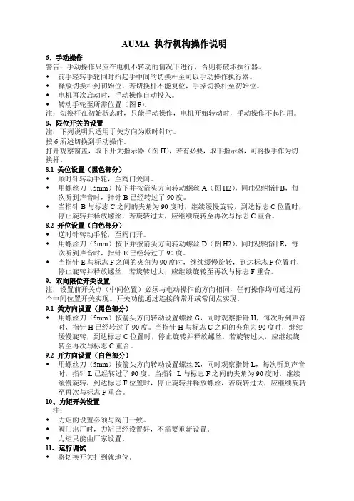
8.1关位设置(黑色部分)♦顺时针转动手轮,至阀门关闭。
♦用螺丝刀(5mm)按下并按箭头方向转动螺丝A(图H2),同时观察指针B,每次听到声音时,指针B已经转过了90度。
♦当指针B与标志C之间的夹角为90度时,继续缓慢旋转,到达标志C位置时,停止旋转并释放螺丝,若旋转过大,应继续旋转至再次与标志C重合。
8.2开位设置(白色部分)♦逆时针转动手轮,至阀门开。
♦用螺丝刀(5mm)按下并按箭头方向转动螺丝D(图H2),同时观察指针E,每次听到声音时,指针E已经转过了90度。
♦当指针E与标志F之间的夹角为90度时,继续缓慢旋转,到达标志F位置时,停止旋转并释放螺丝,若旋转过大,应继续旋转至再次与标志F重合。
9、双向限位开关设置注:设置前开关点(中间位置)必须与电动操作的方向相同,任何操作均可通过两个中间位置开关实现。
开关功能通过连接的常开或常闭点实现。
9.1关方向设置(黑色部分)♦用螺丝刀(5mm)按箭头方向转动设置螺丝G,同时观察指针H,每次听到声音时,指针H已经转过了90度。
当指针H与标志C之间的夹角为90度时,继续缓慢旋转,到达标志C位置时,停止旋转并释放螺丝,若旋转过大,应继续旋转至再次与标志C重合。
9.2开方向设置(白色部分)♦用螺丝刀(5mm)按箭头方向转动设置螺丝K,同时观察指针L,每次听到声音时,指针L已经转过了90度。

Technical InstructionsDocument No. A6V12035775July 7, 2020A-Series IndustrialElectric Actuators AUMA (21,300 and 40,680 lb-in)Siemens Industry, Inc.DescriptionA-Series Industrial Electric AUMA actuators provide precise, durable control of quarter turn Siemens resilient seat butterfly valves. The compact industrial housing is rated to NEMA 6P (IP 68) standards for outdoor use. All models include integrated controls and a manual override handwheel.The standard AUMA models are 120V single phase. All AUMA actuators include six auxiliary switches, torque switches, a position indicator and a heater. Modulating units provide position feedback as standard. Features• Compact, lightweight design and direct mounting • Manual, declutchable override handwheel • Position and motion indicator lights • Push button controls • CE Certified• On/off or modulating control• Output torque 21,300 lb-in (2,407 Nm) to 40,680 lb-in (4,596 Nm) • ISO 5210 for direct mounting• All actuators include a heater to prevent condensation build-up •All modulating units include a feedback potentiometerOrderingActuators can be ordered separately or together with a valve as an assembly.Product NumbersTable 1. A-Series AUMA Industrial Electric Actuators, 120V.Product Number Operating Mode Voltage 50/60 HzTorque 90° Stroke Time*Current Draw (Amps) (lb-in) (Nm) Full Load LockedRotorA226.21K On/Off120 Vac21,300 2,407 60 sec.6.514A226.41K 40,680 4,596 A266.21K Modulating21,300 2,407 A266.41K40,6804,596* Operating times shown are with 60 Hz power supply. Actuators with 50 Hz power supply will be 20% slowerWarning/Caution Notations WARNING: Personal injury or loss of life may occur if you do not perform a procedure as specified.CAUTION:Equipment damage may occur if you do not perform a procedure as specified.Technical Instructions A-Series Industrial Electric Actuators AUMA Document Number A6V12035775June 15, 2020CAUTION:Do not install or use the A-Series Industrial Electric Actuator in or near environmentswhere corrosive substances or vapors could be present. Exposure of the electricactuator to corrosive environments may damage the internal components of thedevice and will void the warranty.Application These actuators are ideal for use on valves for chillers, cooling towers, boilers, heatexchangers and other outdoor applications. The actuators’ advanced electronicsassure reliable compatibility with virtually any analog control signal used in today’sbuilding automation and temperature control systems. The NEMA 6P rated housingprevents any water ingress in outdoor applications. The built-in heater prevents anycondensation build-up inside the housing.NOTE: Use a “liquid tight” conduit connector to maintain NEMA 6P rating. SpecificationsOperating Conditions Ambient Temperature -22°F to 158°F (-30°C to 70°C)Fail Position Loss of supply power - fail-in-placeDuty Cycle On/Off – 15 min. continuous, max. six starts/minuteModulating – 25% intermittent duty Physical Description Motor 120 Vac, Single-Phase, Reversible, PermanentSplit Capacitor Induction MotorMotor Protection 1 Ph-1 thermal switch 284°F (140°C)Class F insulation, tropicalized windingControl Voltage A226.21K and A226.41K: 120 VacA266.21K and A266.41K:Input 4 to 20 mAModular Power Supply 24 VdcOutput Aux. Voltage A226.21K and A226.41K: 115 Vac – 30 mAA266.21K and A266.41K: 24 Vdc – 100 mAFeedback Signal 4 to 20 mAOutput Contacts 6 Output contacts: 6 NO/NC without common 5AOutput Signals Default setting: Fault, End pos. CLOSEDEnd pos. OPEN, Selector sw. REMOTE, Torquefault CLOSE, Torque fault OPENTerminal StripPower Terminals 8 to 10 AWG (6 to 10 mm2)Controls Contacts 14 AWG (2.5 mm2)Heater 24V Internal Supply (5 Watt)Dimensions See Figure 3 and Figure 4.Weight A2x6.21K – 165 lbs. (75 kg)A2x6.41K – 195 lbs. (88 kg)Enclosure NEMA types 6P (IP68)Corrosion Protection: KSConduit entries Plug/socket 100 mm, 2 × 3/4” NPT; 1 × 1-1/4” NPTManual operation To close the valve, turn handwheel clockwise.Drive shaft (valve) turns clockwise in closedirection. 52:1 drive ratioAngle of Rotation 92° maximumCertifications CE CertifiedCSA - Classes C322102 and C3221812(available upon request)A-Series Industrial Electric Actuators AUMA Technical InstructionsDocument Number A6V12035775July 7, 2020Product NumbersTable 2. Product Numbers.Use the product numbers in the following table to order a valve or a valve and actuator assembly. The valve product number consists of the type, action, valve size, disc type, and valve configuration.To order an assembly, add a (-) after the valve product number and then choose the application, actuator, voltage, control signal, end switches followed by a separator (.) and the actuator torque.Siemens Industry, Inc. Page 3Technical InstructionsA-Series Industrial Electric Actuators AUMADocument Number A6V12035775 July 7, 2020Page 4Siemens Industry, Inc.Mounting and InstallationAll A-Series industrial electric actuators are suitable for direct mounting on Siemens resilient seat butterfly valves.NOTE:The standard mounting position for the actuator is to orient the base of the actuator parallel to the pipeline. •To mount an actuator on a vertical pipe, position the unit with the conduit entries on the bottom to prevent condensation from entering the actuator through its conduits.• Use a “liquid tight” conduit connector to maintain NEMA 6P rating.Service The resilient seat butterfly valve and actuator are maintenance-free.WiringCAUTION: •When wiring an A-Series Industrial Electric Actuator for two-position(on/off) control and the power to the actuator is commanded to be off, you must ensure that there is no extraneous or leakage voltage between hot and common. Leakage voltage greater than 3 Vac can cause actuator failure.• When wiring an A-Series Industrial Electric Actuator for two-positioncontrol, the controller should use at minimum a one-second time delay for command signal reversal. Instantaneous command reversals may cause actuator failure.Figure 1.. On/Off .NOTE:Use this A-Series Industrial Electric Actuator only to control equipment under normal operating conditions. Where failure or malfunction of the electric actuator could lead to personal injury or property damage to the controlled equipment or other property, additional precautions must be designed into the control system. Incorporate and maintain other devices such as supervisory or alarm systems or safety or limit controls intended to warn of, or protect against, failure or malfunction of the electric actuator.Figure 2. Modulating.A-Series Industrial Electric Actuators AUMA Technical InstructionsDocument Number A6V12035775July 7, 2020 Information in this publication is based on current specifications. The company reserves the right to make changes in specifications and models as design improvements are introduced. Products or company names mentioned herein may be the trademarks of their respective owners. © 2020 Siemens Industry, Inc.Siemens Industry, Inc. Smart Infrastructure1000 Deerfield Parkway Buffalo Grove, IL 60089 USA + 1 847-215-1000Your feedback is important to us. If you havecomments about this document, please send themto***************************************Document No. A6V12035775Printed in the USAPage5of 5DimensionsFigure 3. Model A2x6.21K Actuators.Figure 4. Model A2x6.41K Actuators.。
操作说明手册的封面内容翻译(中英文对照):Multi-turn actuators万向驱动装置SA07.1-SA48.1 (产品型号)SAR 07.1-SAR 30.1 (产品型号)AUMA NORM (AUMA是这个阀门生产厂的品牌名称)AUMA标准Operation instructions (操作手册)目录内容:Scope of these instructions:本手册内容介绍的范围包括:These instructions are valid for multi-turn actuators for Open-close duty, SA 07.1-SA 48.1 ,and multi-turn actuators for modulating duty, SA07.1-SA 30.1.本手册的说明适应型号为SA 07.1-SA 48.1、具有开启-关闭功能系列的万向驱动装置和型号为SA07.1-SA 30.1、具有调节功能系列的万向驱动装置有效。
These operations instructions are only valid for “clockwise closing”, i.e. drivenshaft turns clockwise to close the valve.这些操作说明只对"顺时针关闭"有效,即:驱动轴顺时针转动关闭阀门。
.Safety instructions (安全说明 )1.1 Range of application (应用的范围 ) AUMQ multi-turn actuators are designed for the operation of industrial valves, e.g, globe valves, butterfly valves and ball valves. For other applications, please consult us. AUMA is not liable for any applications. Such risk lies entirely with the user. AUMQ万向驱动装置是为工业用阀所设计的,例如:工业生产常用球瓣阀,蝶阀和球阀。
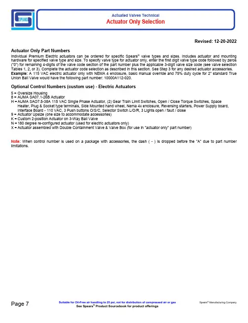
Actuated Valves TechnicalActuator Only Selection5 =8 =H =9 =K =N =X =Oversize HousingAUMA SA07.1-26B ActuatorAUMA SAO7.5-38A 115 VAC Single Phase Actuator, (2) Gear Train Limit Switches, Open / Close Torque Switches, SpaceHeater, Plug & Socket type terminals, Side Mounted hand wheel, Nema 4x enclosure, Reversing starters, Power Supply board, Interface Board - 110 VAC, 3 Push buttons O/S/C, Selector Switch L/O/R, 3 Lights open / fault / closeActuator Upsize (one size to accommodate accessories)Custom 2-position Actuator on 3-Way Ball Valve180 degree re-configured actuator (used for electric actuators only)Actuator assembled with Double Containment Valve & Valve Box (for use in "actuator only" part number)Page 7Suitable for Oil-Free air handling to 25 psi, not for distribution of compressed air or gas Spears ® Manufacturing CompanySee Spears ® Product Sourcebook for product offerings Revised: 12-20-2022Actuator Only Part NumbersIndividual Premium Electric actuators can be ordered for specific Spears ® valve types and sizes. Includes actuator and mounting hardware for specified valve type and size. To specify valve type for actuator only, enter the first digit valve type code followed by zeros ("0") for remaining 4-digits of the valve code section of the part number plus the applicable 3-digit valve size code (see valve selection Tables 1, 2, or 3). Complete the actuator code selection as described in this section. See Step 3 for any desired actuator accessories. Example: A 115 VAC electric actuator only with NEMA 4 enclosure, basic manual override and 75% duty cycle for 2" standard True Union Ball Valve would have the following part number: 10000A112-020.Optional Control Numbers (custom use) - Electric ActuatorsNote: When control number is used on a package with accessories, the dash ( - ) is dropped before the "A" due to part number limitations.。
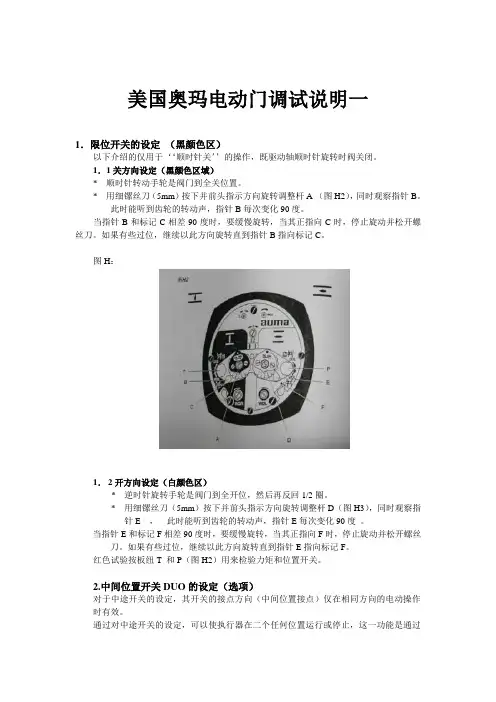
美国奥玛电动门调试说明一1.限位开关的设定(黑颜色区)以下介绍的仅用于‘‘顺时针关’’的操作,既驱动轴顺时针旋转时阀关闭。
1.1关方向设定(黑颜色区域)* 顺时针转动手轮是阀门到全关位置。
* 用细镙丝刀(5mm)按下并前头指示方向旋转调整杆A (图H2),同时观察指针B。
此时能听到齿轮的转动声,指针B每次变化90度。
当指针B和标记C相差90度时,要缓慢旋转,当其正指向C时,停止旋动并松开螺丝刀。
如果有些过位,继续以此方向旋转直到指针B指向标记C。
图H:1.2开方向设定(白颜色区)* 逆时针旋转手轮是阀门到全开位,然后再反回1/2圈。
* 用细镙丝刀(5mm)按下并前头指示方向旋转调整杆D(图H3),同时观察指针E ,此时能听到齿轮的转动声,指针E每次变化90度。
当指针E和标记F相差90度时,要缓慢旋转,当其正指向F时,停止旋动并松开螺丝刀。
如果有些过位,继续以此方向旋转直到指针E指向标记F。
红色试验按板纽T 和P(图H2)用来检验力矩和位置开关。
2.中间位置开关DUO的设定(选项)对于中途开关的设定,其开关的接点方向(中间位置接点)仅在相同方向的电动操作时有效。
通过对中途开关的设定,可以使执行器在二个任何位置运行或停止,这一功能是通过中途开关上的NC或NO的点完成。
* 操作执行器将阀门运行到预定位置2.1关方向设定(黑颜色区)* 用细镙丝刀(5mm)按下并前头指示方向旋转调整杆G(图H3),同时观察指针H ,此时能听到齿轮的转动声,指针H每次变化90度。
当指针H和标记C相差90度时,要缓慢旋转,当指针H正指向C时,停止旋动并松开螺丝刀。
如果有些过位,继续以此方向旋转直到指针H指向标记C。
2.2开方向设定(白颜色区)用细镙丝刀(5mm)按下并前头指示方向旋转调整杆K(图H3),同时观察指针L ,此时能听到齿轮的转动声,指针L每次变化90度。
当指针L和标记F相差90度时,要缓慢旋转,当指针L正指向F时,停止旋动并松开螺丝刀。
操作说明手册的封面内容翻译(中英文对照):Multi-turn actuators万向驱动装置SA07.1-SA48.1 (产品型号)SAR 07.1-SAR 30.1 (产品型号)AUMA NORM (AUMA是这个阀门生产厂的品牌名称)AUMA标准Operation instructions (操作手册)目录内容:Scope of these instructions:本手册内容介绍的范围包括:These instructions are valid for multi-turn actuators for Open-close duty, SA 07.1-SA 48.1 ,and multi-turn actuators for modulating duty, SA07.1-SA 30.1.本手册的说明适应型号为SA 07.1-SA 48.1、具有开启-关闭功能系列的万向驱动装置和型号为SA07.1-SA 30.1、具有调节功能系列的万向驱动装置有效。
These operations instructions are only valid for “clockwise closing”, i.e. driven shaft turns clockwise to close the valve.这些操作说明只对"顺时针关闭"有效,即:驱动轴顺时针转动关闭阀门。
.Safety instructions (安全说明 )1.1 Range of application (应用的范围 ) AUMQ multi-turn actuators are designed for the operation of industrial valves, e.g, globe valves, butterfly valves and ball valves. For other applications, please consult us. AUMA is not liable for any applications. Such risk lies entirely with the user. AUMQ万向驱动装置是为工业用阀所设计的,例如:工业生产常用球瓣阀,蝶阀和球阀。
AUMA MATIC Compacts consist of motor controls, local controls (optional) and other control elements, which are required to operate an electric actuatorScopeThese instructions are intended to cover the AUMA MATIC compact in both the C and S configuration with an AUMA interface board. These instructions are for general startup and basic troubleshootingFor calibration/setting of optional Electronic Positioner 601 or Pulse Timer, refer to the appropriate instructions.Electrical ConnectionsCAUTION:Observe safety regulations.• Verify that the motor and control voltages correspond with equipment supplied. Refer to the nameplate on motor and/or AUMA MATIC Compact.39• Attach conduit or cables following approved practices.CAUTION:Appropriate conduit and sealing methods must be followed to ensure the NEMA rating for the enclosurefurnished• Connect field wiring according to wiring diagram supplied. If drawing is not available, contact the nearest AUMA office with the Sales Order Number located on the actuator nameplate. A replacement drawing will be provided.• Actuator limit switches and optional RWG (position feedback transmitter), if supplied, should be set using appropriate setting instructions prior to proceeding.The AUMA MATIC Compact contains a programmable logic board. The following DIP switch settings are made on the logic board. The factory has preset the logic board switches per the order requirements, if requested, prior to shipment.Dip Switch S1Position 1: Limit switch seating in the closed direction.Position 2: Torque seating in the closed direction.Note:Limit switch closed must be set just prior to the torque seating position for closed indication or a fault occur.willClosed direction is clockwise output of electric actuator. For counter clockwise seating options consult factory.Dip Switch S2Position 1: Seal-in circuit remote closePosition 2: Seal-in circuit remote openPosition 3: Seal-in circuit local closePosition 4: Seal-in circuit local openPosition 5: Optional blinker switch offPosition 6: Torque switch included in collective fault signalTest Run• Switch selector switch to local position. If local control is not supplied, refer to electrical drawing for reference to local operation.• Turn control switch or operate push-button in either open or close direction.• If actuator fails to operate, access the interface board by removing cover and checking to see if the following LEDS are illuminated. An LED that is on signals a fault.V14 LED• Motor (line power) phasing is incorrect. Reverse U1 and W1 at field connection terminals (3Ø only) or there may be a loss of phase. Check incoming 3Ø power.V15 LED• Torque switch is tripped. Check torque switch settings. Declutch actuator and manually move to a different position to ensure smooth operation.V14 and V15• Thermal switch in motor is tripped. Feel motor, and if hot, wait until it cools down, and try operation again. If motor continues to overheat or motor is cool and thermal switch is tripped, consult factory.• Optional overload relay is tripped. Standard version is set in auto reset mode. The manual reset is located on top of the overload which can be accessed by removing the circuit board assembly.If LED’s Are Not Illuminated, But Actuator Will Not Operate:• No line power.— Check for loose connection.— Check for correct voltage at terminals U1, V1 and W1.— Check for correct capacitor connection (1Ø).• Field jumpers are not correct.— Verify the field wiring matches electrical drawing supplied by AUMA.• Fuses are open.CAUTION: Before Checking/replacing fuses, ensure all power is disconnected.— Remove selector switch/push-button cover. Primary fuse(s) are located in black fuse holders.— Secondary fuses are located on power supply board which can be accessed by removing the circuit board where the primary fuse(s) are located.Note: Replace fuse(s) with same type and size. For fuse sizes, refer to appropriate service instruction.Actuator Operates Automatically as Soon as Power is AppliedThe AUMA MATIC with an interface board has an emergency override circuit which can be programmed to operate the actuator open or closed. Programming is accomplished by adding or removing the appropriate jumper at solder links B1 and B2--Jumper B1 for emergency closed, jumper B2 for emergency open.Check the electrical drawing for correct emergency override circuit configuration. A normally closed contact in the override circuit will, upon opening, force the actuator to the pre-programmed position. When the contact returns to the normally closed position, the actuator will respond normally.Interface BoardLogic BoardPower SupplyMonitor ControlBoardInterface BoardLogic BoardProgramming• Refer to Figure 1.• The Logic Board has 3 sets of switches S1-2, S2-2 and S3-2.• Switches S1-2 and S3-2 allow for either limit or torque seating in closed and open positions.Switch S1-2• In position 1, the actuator is set for limit seating in the clockwise direction. • In position 2 the actuator is set for t orque seating in the clockwise direction.Switch S3-2• In position 1, the actuator is set for limit seating in the counterclockwise direction. •In position 2 the actuator is set for torque seating in the counterclockwise direction.Switch S2-2Switch Position S2-2 “ON”S2.1 Remote seal in for clockwiseS2.2 Remote seal in for counter clockwise S2.3 Local seal in for clockwiseS2.4 Local seal in for counter clockwise S2.5 Blinker transmitter offS2.6 Torque switch included in collectivefault signalAlso provided on the Logic Board are four solder links. When the soldered link is present on pads J1 and J3, the integral open and close lights on the Monitor Control board within the AUMA Matic will both be on in a intermediate valve position. When the soldered link is present on pads J2 and J4 the integral open and close lights on the Monitor Control board will both be off in an intermediate valve position. Figure 1D o w n i s o n1 21 2Solder links J1-J4。
1.限位设定2.力矩设定3.AUMA TIC 控制头的设定:(1)简介按钮说明:共有四个按钮,选择开关打在LOCAL就地控制时,从上至下依次是开、停、关、RESET复位。
选择开关打在OFF时,从上至下依次是上翻叶、下翻叶、确认、退出。
菜单分组,有S组、M组、D组。
S组用来显示,M组用来设定,D组用来诊断S组有S0、S1、S2、S3。
开始时液晶屏幕上显示的是S0,共四行:第一行是控制方式,第二行是控制命令,第三行是位置反馈,第四行是执行器当前状态。
下翻叶可调出S1故障说明,S2报警说明,S3未准备好说明。
M组有M0、M1、M2、M3、M4。
如果现在是S0菜单,将选择开关打在OFF位,按RESET两秒以上会出现M0主菜单MAIN MENU。
主菜单MAIN MENU包括:LANGUAGE/CONTRAST 语言/屏幕亮度的对比度M0SETTING设定M1OPERATIONAL DATA运行数据M2EL。
NAME PLATE电子铭牌M3CONFIGURATION配置设定M4将选择开关打在OFF位,长按RESET可调出D组,D组有D0、D1、D2。
很多很多。
其中D2内部故障,D3内部报警,D4配置错误是最重要的三个。
(2)具体设定:M11里设定用什麽方式停机,可选择到限位停机或者过力矩停机。
一般选为到限位停。
M12 里设定执行器的开力矩值和关力矩值,是最大力矩值的百分之几。
M13里设定就地控制的各参数。
其中M13X0设定就地是否自保持,一般选为自保持。
M13X1设定有无闪光,一般选为闪光。
M13X2、M13X3、M13X4、M13X5、M13X6是设定控制面板上的五个指示灯代表的意义。
默认设定是从左至右是关到位、关过力矩、电机过热、开过力矩、开到位。
M14是输入/输出的设定。
其中M14X0是远控时是否自保持。
注意调节型执行器一定用OFF非自保持。
M14X1是设定报警输出。
默认设置是当发生故障时有报警输出。
AUMA电动执行机构操作手册多转式电动执行机构是一种性能比较稳定的机电一体化装置。
如果按照以下的要求正常操作,可以避免对设备造成意外的损坏。
1.运输和保存¾在阀门运往安装现场的过程中,必须有适当的包装。
¾严禁用将起重链条或起重钩安装在阀门手轮上作为阀门的起重部位。
¾阀门必须室内保存且通风良好,干燥。
¾将阀门保存在货架上或木制框架上以避免潮气对阀门造成损坏。
¾必须将阀门遮盖起来,以防止阀门受到灰尘、杂物的污染。
¾对暴露在外面的部分,必须采取措施,防止腐蚀。
2.使用条件AUMA多转式执行机构可以正在以下条件下正常使用:型号最低温度(℃)最高温度(℃)型号最低温度(℃)最高温度(℃)SA(标准) -25 80 SAR -25 60开关型的电动执行机构SA系列设计的主要目的是为了使阀门能够快速关闭(按照VDE0530)。
3. 阀门和齿轮箱的安装阀门和齿轮箱的安装和控制箱可以在任何位置安装。
¾检查减速箱的输出法兰是否和阀门及齿轮箱的法兰相配。
注意:安装时必须保证法兰上的连接螺栓的安装轻松、自如。
¾输出连接口为A型:插口的螺纹必须和阀杆螺纹相配。
¾如果在定货是没有注明螺母的方向,在供货时只提供没有打孔或没有攻丝的螺母。
阀杆螺母的安装见13所述。
¾对于型号为B1,B2,B3的输出装置设计为锥形轴连接或键连接。
(一般情况下执行ISO5210 标准)。
¾检查锥形轴和键槽是否和阀门及齿轮箱的输入轴相符。
¾将执行机构、阀门及齿轮箱的安装表面清理干净。
¾在阀门及齿轮箱的输入轴表面涂上少量润滑油。
¾将执行机构放在阀门或齿轮箱上,并将螺栓对角紧固(紧固力矩见8.8)4.手动操作手动-电动操作的切换:注意:只有在驱动装置停止运转的情况下方可用手轮进行操作。
¾将手动-电动转换手柄抬起(在手轮的中间部位大约850),手动轻轻的转动手轮。
奥玛AUMA旋转式电动执行器使用手册本手册适用于 SA、SAL、SAH、SAR、SAEx、SAREx型的奥玛AUMA执行器。
目录1. 运输与保管2. 工作环境条件3. 往阀门上安装4. 手动5. 电气连接6. 试运行7. 调整限位开关8. 调整DUO限位开关(选购件)9. 调整力矩开关10. 调整机械式位置指示器(选购件)11. 调整电位器(选购件)12. 调整电感式限位传感系统IWG和电子式阀位计RWG(选购件)13. 螺纹套筒的最后加工(连接方式A)14. 维护1 运输与保管- 在运往安装地点的途中,一定要采用坚固的包装,- 千万不要利用执行器上的手轮来栓结起重用的锚具索具等,- 应在干燥通风的室内保管,为防止地面潮气侵入,应置于货架上或用木板隔潮,- 应加以遮挡,防止沾染灰尘和脏物,- 凡是光亮的表面均应涂抹适当的防腐剂。
2 工作环境条件AUMA旋转式执行器的工作环境温度为:SA -25℃~ +80℃(标准工况) SAR -25℃~ +60℃SAL -60℃~ +60℃ SAEx -25℃~ +40℃SAH 0℃~ +120℃SAREx -25℃~ +40℃SA型适用于短时工作制S2─15min (依据VDE 0530)。
SAR型适用于S4─25%ED (依据VDE0530),允许的开关频度可参看SAR 最新样本。
3 往阀门上安装AUMA旋转式执行器可以安装或工作于任意方位。
●首先检查阀门与齿轮箱的连接法兰是否匹配。
注意:法兰的定心是按余隙配合进行的!对于A型连接,螺纹套筒的螺纹必须与阀杆的螺纹相一致。
如果订货时如未讲明螺纹该如何加工,则螺纹套筒在出厂时不钻孔或者只进行粗钻。
其最终加工方法参见第13节。
对于B1,B2,B3,B4型连接,则把螺纹套筒钻好孔和键槽后发货(一般依据 ISO 5210 进行)。
●检查螺纹套筒的孔与键槽,是否同阀门-减速器输入轴上的孔和键槽一致。
●对执行器和阀门-减速器的法兰接合面,进行全面除油。
AUMA执行器1.AUMA执行器产品介绍AUMA执行器不论是其控制部分还是减速机构,最显著的特点就是它的模块化设计,使其具有高度的配置和使用的灵活性。
AUMA电动执行器包括多转式(multi-turn)、部分转角式(part-turn)和直行程(linear)三种。
其中多转式的力矩范围为10---32000NM,部分转角式力矩范围25---360000NM,直行程的推力为3.8---217KN。
AUMA多转式执行器SA系列主要应用于开关插板门以及球阀;部分转角式主要分为AS系列和SG系列,其转角0—90度行程时间为4---180秒,主要应用于蝶阀控制;直行程执行器实际上是由多转式执行器(SA)与线性减速机构(LE)组合而成,它主要是通过推拉实现对阀门的控制。
2.在用的AUMA执行器2.1 直行程:直行程执行器(亦称为直推直拉式)主要应用于automate globe vavle、butterfly vavle、modulating vavle的控制。
2.1.1 普通AUMA执行器:无论是何种型号的AUMA执行器,它的基本操作模式都有两种,即本机操作模式(LOCAL)和远程控制模式(RAMOTE);其中远程控制模式还包括远程开关量控制和远程模拟量控制两种方式。
在本机控制模式下,执行器可以通过按钮进行操作,方便检修。
普通AUMA执行器的就地调整主要包括行程、力矩开关的调整和零满调整。
1)行程限位开关的调整:首先要用手轮将执行器操作到全关位置,也可用力矩关到底然后回调若干定为全关行程限位位置(此位置须由阀门厂家或或管阀班人员确认),然后压下调试轴A,并以箭头所示方向旋转,可以感觉和听到驱动轴齿轮啮合转动的咯哒声,同时指针B以90度的步进速度旋转,当指针B刚好指向红点C时,停止转动A,则限位定好。
(如果指针B调过红点C或是A轴旋转过头,不要反向调整,继续按箭头所示方向进行调整,重新进行限位)。
全开位置的行程限位方法一样,不再赘述。
PV 1236移动检测台移动检测台PV 1236可检测和校准AUMA 多回转执行器SA和部分回转执行器SG的机械和电气性能。
以前的检测只能由制造商完成。
现在可通过移动检测台PV 1236在现场轻松实现检测。
当由于维修等原因需要重新校准执行器时,这一优势更能得到突出体现。
可完成以下设置和测量校准扭矩开关 测量执行器的失速扭矩 设置限位开关 测量输出速度 监控或显示开关功能移动检测台PV 1236可检测最大扭矩值高达500Nm的电动执行器(1000Nm作为可选项)。
以下为AUMA执行器的型号和规格。
1 AUMA防爆型执行器和其它制造商的执行器并不提供用于电气连接的连接器,而是以端子连接替代。
因此检测带端子排连接的执行器必须由带证的电工完成。
2 检测台检测的扭矩值可高达1000Nm(可选)通过使用适合的适配器也可以检测有其它制造商生产的执行器。
设计[6][7][1] 服务单元 PV 788 B此单元用于执行器的电压供应,操作以及所有相关电气值的测量。
它通过标准的AUMA插拔式连接器提供执行器的电气进行连接。
其它电气连接的执行器要求配有适配器。
可应客户要求提供。
[3]安装法兰用于安装待检测的执行器。
根据客户要求, 也可提供其它执行器制造商采用的特殊规格的安装法兰。
[4] 制动系统包括2个带有卡钳的制动盘。
每个卡[6] 远程控制[7] 扭矩打印机不在AUMA的供货范围之内。
服务单元 PV 788 B服务单元PV 788 B带有远程控制服务单元PV 788 B可检测带有3相交流电机的执行器。
可完成以下任务: 检测执行器的电压 通过远程控制检测执行器的运行 检测所有执行器的性能 检测所有相关的电气值服务单元PV 788 B打开之后, 它将检测所供电压的相位顺序, 并自动调整成为顺时针关闭的执行器。
性能检测远程控制的按钮可检测执行器以下的基本性能: 开方向的运行 关方向的运行 停止通过面板上的LED, 可以检测限位开关,中途开关以及扭矩开关的功能。
auma matic的结构及其功能说明带auma matic的电动执行器由如下部分组成:执行器基本出力部分auma norm 安装在执行器基本部分上的可编程点机一体化控制单元auma matic 将电机一体化控制单元与电动执行器组合到一起有以下几种优点:与普通的不带控制单元的执行器的布线相比由于大大简化了现场的布线工作量,因此可以节约大量的费用。
由于继电器不是安装在遥远的电气控制柜中,因此在扭矩开关或行程开关被侵压以后电机会立刻停止转动不会产生过长的延时。
可以被轻易而灵活地组合到各种各样的过程控制系统中或者组合到一个标准化的现场总线系统中,例如:profibus-fms,profibus-dp,interbus-s或modbus-rtu。
电机一体化控制单元auma matic由以下几个模块组成:用于控制电机电源的换向接触器。
操作和信号电路板-带有初级熔断器,和用于将现场按扭发出的控制命令传递到电子电路的继电器;应客户的要求还可带上做为任选件的指示灯。
接口板-带有用于隔离内部信号和外部信号之间电位差的光电隔离器,继电器和发光二极管指示灯。
以smd技术设计的路基板-其上装有c-mos场效应管。
它提供了对内部信号和开关信号之间的连接进行编程以及用dip开关设定电机控制的可能性。
连接执行其本身auma norm和电机一体化控制单元auma matic的auma插拔式电气连接器。
为用户接线而提供的auma插拔电气连接器。
带有现场/远程选择器电机控制单元供电用的电源供应单元。
电机一体化控制单元auma matio的模块化设计结构使得对其配置的修改变得非常容易。
在不带一体化控制单元得执行器(auma norm)上的auma插拔式电器连接器与电机一体化控制单元(auma matic)上的电气连接器是完全相同的。
这使得auma电动执行器得升级改型非常容易。
电动机得一体化控制单元auma matic可以被安装在以下型号规格得执行器上:多回转执行器: sa07.1-sa16.1(用于开-闭控制)sam07.1-san16.1(用于调节控制)部分回转执行器:sg05.1-sg12.1 最新开发得纺爆型auma matic可以直接安装到auma norm防爆型执行器sa ex,sam ex或sg ex上,使其改型升级为带电动机一体化控制单元的防爆型电动执行器。
篇二:auma 说明书中英文对照文稿-world版可编辑操作说明手册的封面内容翻译(中英文对照):multi-turn actuators 万向驱动装置sa07.1-sa48.1 (产品型号)sar 07.1-sar 30.1 (产品型号) auma norm (auma是这个阀门生产厂的品牌名称) auma标准operation instructions (操作手册) 目录内容:scope of these instructions: 本手册内容介绍的范围包括:these instructions are valid for multi-turn actuators for open-close duty, sa 07.1-sa 48.1 ,and multi-turn actuators for modulating duty, sa07.1-sa 30.1.本手册的说明适应型号为sa 07.1-sa 48.1、具有开启-关闭功能系列的万向驱动装置和型号为sa07.1-sa 30.1、具有调节功能系列的万向驱动装置有效。
these operations instructions are only valid for “clockwise closing”, i.e. driven shaft turns clockwise to close the valve.这些操作说明只对顺时针关闭有效,即:驱动轴顺时针转动关闭阀门。
.safety instructions (安全说明 ) 1.1 range of application (应用的范围 ) aumq multi-turn actuators are designed for the operation of industrial valves, e.g, globe valves, butterfly valves and ball valves. for other applications, please consult us. auma is not liable for any applications. such risk lies entirely with the user. aumq万向驱动装置是为工业用阀所设计的,例如:工业生产常用球瓣阀,蝶阀和球阀。
如有其他的用途,请联系我们。
auma并不对任何生产应用都负责。
用户的这种冒险完全不必要。
observance of these operation instructions is considered as part of the actuator’s designated use. 遵守操作说明是执行器指定用途的一部分。
1.2 short description(概要)auma multi-turn actuators type sa 07.1-sa 48.1 and sar07.1-30.1 have a modular design.型号为sa 07.1- sa4 8.1 和sar07.1-sar 30.1 auma万向驱动装置有一种标准化的设计。
the limitation of travel is realized via limit switches in both end positions.阀位限制通过设计在阀门开或关到两个极限位置处的限位开关来实现。
torque seating is also possible in both end positions. the type of seating is stated by the valve manufacturer.阀门在开或关到位时,扭转插座也是可能存在的。
阀门制造商对这种插座的类型作了规定。
during electrical operation certain parts inevitably carry lethal voltages.在操作电气接线期间,某些部分不可避免带有对人体致命的电压。
work on the electrical system or equipment must only be carried out by a control and supervision of such an electrician and in accordance with the applicable electrical engineering rules. 因此,当开始着手电气系统或电气设备这方面工作时,必须参照相应的电气工程规章,在专业的电气工程师的指导和监督下进行。
1.4 maintenance 维护the maintenance instructions (refer to page 18) must be observed, otherwise a safe operation of the actuator is no longer guaranteed.维护手册(参考第18 页)必须严格遵守,否则执行器的安全操作将不能被保证。
1.5 warnings and notes 警告和注意事项non-observance of the warnings and notes may lead to serious injuries or damages. qualified personnel must be thoroughly familiar with all warningsand notes in these operation instructions. 不遵守那些警告和注意事项可能会导致严重的人身伤害。
具有操作资格的人员必须完全熟悉和掌握操作说明中的所有注意和警告事项,correct transport, proper storage, mounting and installation, as well as operation.正确运输,适当贮存,架设和安装,以及细心调试对确保减少问题的出现和安全操作是很重要的。
the following references draw special attention to safety-relevant procedures in these operation instructions. each is marked by the appropriate pictograph.一个都用一个恰当的图标作了标记。
this pictograph means: note! 这个图标的含义:注意!“note” marks activities or procedures, which have major, influence on the correct operation. non-observance of these notes may lead to consequential damage.注意标明这些行为或者过程将对正确操作有主要的影响。
不遵守这些注意事项可能导致由这些原因引起的伤害。
the pictograph means: electrostatically endangered parts!这个图标的含义:此处有静电!if this pictograph is attached to a printed circuit board, it contains parts, which may be damaged or destroyed by electrostatic discharges. if the boards need to be touched during setting, measurement or for exchange, it must be assured that immediately before a discharge through contact with an earthed metallic surface (e. g, the housing) has taken place. 如果这个图标附在印刷电路板上,它包含的部分部件可能会因为存在释放静电而造到损坏或者破坏。
如果印刷电路板在安装、测量时需要被接触,必须确保通过连接一根金属导线接地(如房子)以放掉静电。