GearTrax汉化说明(重要)
- 格式:pdf
- 大小:86.15 KB
- 文档页数:2
垃圾工杰克X新手教程设置篇全英文知识汉化说明本资料来自百度贴吧,针对口袋巴士玩家的阅读习惯进行了一些修改和编辑。
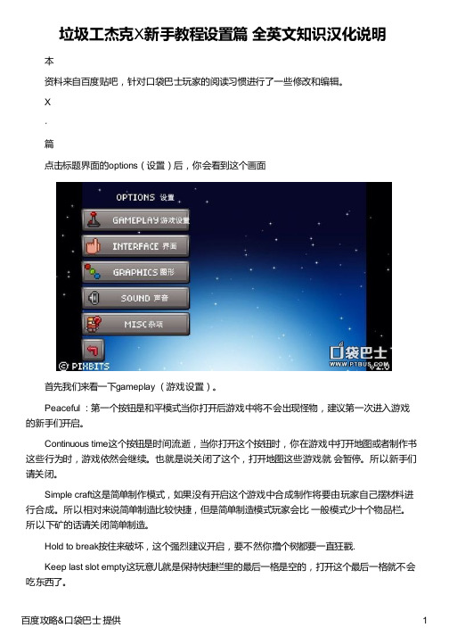
X·篇点击标题界面的options(设置)后,你会看到这个画面首先我们来看一下gameplay (游戏设置)。
Peaceful :第一个按钮是和平模式当你打开后游戏中将不会出现怪物,建议第一次进入游戏的新手们开启。
Continuous time这个按钮是时间流逝,当你打开这个按钮时,你在游戏中打开地图或者制作书这些行为时,游戏依然会继续。
也就是说关闭了这个,打开地图这些游戏就会暂停。
所以新手们请关闭。
Simple craft这是简单制作模式,如果没有开启这个游戏中合成制作将要由玩家自己摆材料进行合成。
所以相对来说简单制造比较快捷,但是简单制造模式玩家会比一般模式少十个物品栏。
所以下矿的话请关闭简单制造。
Hold to break按住来破坏,这个强烈建议开启,要不然你撸个树都要一直狂戳.Keep last slot empty这玩意儿就是保持快捷栏里的最后一格是空的,打开这个最后一格就不会吃东西了。
接下来是interface(界面设置)。
tap to move items:轻触移动物品,如果没打开这个选项,那么你在物品栏里移动物品要靠“拖”。
打开这个就只要点了。
这就看个人习惯。
item outlines:这个选项请打开,打开后物品会以它的类型而绘制不同颜色的方框,比如白色线是合成材、紫色是收藏品、绿色线是可以吃的东西、黄色是可以放置的物品、黑色是垃圾、蓝色是工具等等,进了游戏里就知道啦。
item count in book:这是在制作书中查看制作配方时,能显示你背包里这个材料数量的选项。
close inv. to book:若这个选项开启,当你制作的时候打开制作书会退出制作栏。
show craft note:这个选项是能够自动打开玩家刚入手的制作配方的选项raphics(图形)如果你的jjx很卡或者常常闪退那么你可以试试更改这个设置。
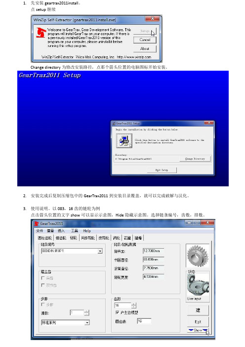
1.先安装geartrax2011install。
点setup继续
Change directory为修改安装路径,点那个箭头位置的电脑图标开始安装。
2.安装完成后复制压缩包中的GearTrax2011到安装目录覆盖,就可以完成破解与汉化。
3.使用说明。
以083,16齿的链轮为例
点击箭头位置的文字show可以显示示意图,Hide隐藏示意图。
选择链条编号,齿数,排数。
点键槽,
再点链轮,在示意图中就可以看到大概的尺寸。
符合要求以后点击建,就自动在solidworks 里面创建3D 模型。
不用再像以前的版本要改solidworks 的语言环境。
1.不用键槽
时选None 。
2.需要键槽
根据需要选
正方形还是
矩形。
此处为柄的外径 此处为柄宽度
此处为内孔直径。
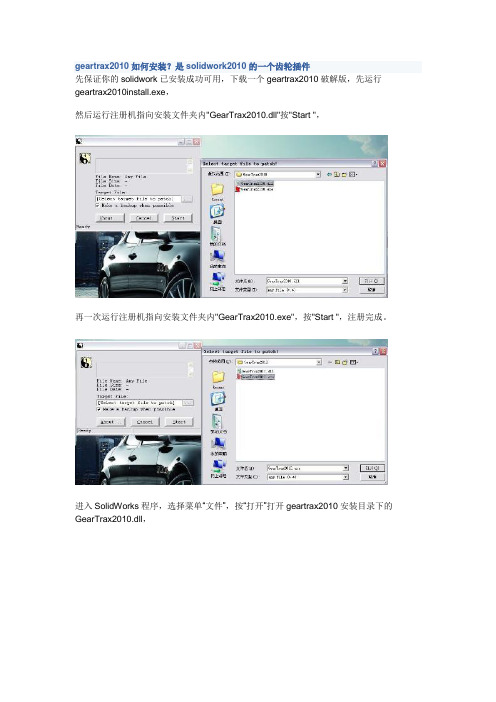
geartrax2010如何安装?是solidwork2010的一个齿轮插件
先保证你的solidwork已安装成功可用,下载一个geartrax2010破解版,先运行geartrax2010install.exe,
然后运行注册机指向安装文件夹内"GearTrax2010.dll"按"Start ",
再一次运行注册机指向安装文件夹内"GearTrax2010.exe",按"Start ",注册完成。
进入SolidWorks程序,选择菜单“文件”,按“打开”打开geartrax2010安装目录下的GearTrax2010.dll,
程序载入后就可以看到插件选单中多了GearTrax2010项目,
如果点击它无法载入,也不要紧直接双击安装程序的GearTrax2010程序图标,也能打开程序
不过因为程序本身不支持中文,所以生成的齿轮不完整,如图
这是需要我们修改solidwork界面为英文界面,点击“工具”菜单,“系统选项”,勾选“使用英文菜单”“使用英文特征和文件名称”两项,
重启solidwork,界面已改成英文(不画齿轮时可以取消勾选,恢复中文菜单),这是用geartrax2010生成齿轮就OK了!
另外你可以直接下载一个GearTrax2009(绿色汉化破解版)直接解压可用,又是中文应该也能
支持solidwork2010。
来自: /mfqfqm122/blog/item/3eb9c924ca3eaa3ec89559d5.html。

5X OPERATING MANUALOPERATING MANUALTABLE OF CONTENTSWARNING AND TABLE OF CONTENTS (2)IMPORTANT SAFETY INFORMATION (3)SPECIFICATIONS (4)WHAT’S IN THE BOX (5)ASSEMBL Y (6)OPERATING INSTRUCTIONS (7)MAINTENANCE (10)LIMITED MANUFACTURER’S WARRANTY (11)2IMPORTANT SAFETY INFORMATIONFailure to heed these markings may result in personal injury and/or property damage:1. DO NOT use the 5X on slopes and inclines beyond stated limits.2. DO NOT submerge the 5X in water (salt or fresh) or leave it in water for prolonged periods, since this can damage the gears and erode lubricants.3. DO NOT use your drill on the 5X’s high gear. (Attachment sold separately)4. Carefully read all instructions. The operator of the 5X must exercise common sense, caution, and full judgment when assessing situations not covered or cautioned in this manual.5. The 5X is designed for specific applications only. Trailer Valet will not be responsible for issues arising from modifications made onto the device. Do not modify the device or use the device for any application other than its intended purpose. Do not exceed the designated weight limits.6. Stay alert! Do not operate if you are tired. Do not operate the device while under the influence of drugs or alcohol. Read prescription warning labels to determine if the use of prescription drugs may impair your ability to operate the device.7. As with all devices with moving parts, do not wear excessively loose clothing as it may become caught, resulting in injury. Tie back and secure long hair.8. Have a second person guide your trailer’s movements while using the 5X to avoid property damage when necessary, especially in narrow or poorly visible areas.9. Operator and bystanders should never place any part of the body under or in the path of any portion of this product or the load being supported or moved.10. This product must be installed and used in strict accordance with these instructions.11. Always remember to set the brakes before leaving or if you are having trouble maintaining control of the trailer.12. Always read and understand your drill/driver operator’s manual and instructions.13. Before each use of the 5X, check for damaged parts. Carefully inspect the device for any part that appears to be damaged to determine if the device will operate properly. Check for alignment and secure mounting of all moving parts. If the device is neither aligned, secured, or both: DO NOT use the device.14. When servicing, use only factory replacement parts.15. The 5X is not intended to be used as a transport device for the implement it is attached to.16. Have wheel blocks in place before/after use and ready in case of emergency.17. Never exceed the maximum rated capacity. Refer to the operating manual or decals on the product to obtain rated capacity. If uncertain, contact Customer Support at (844) 846-9344oremail:************************.18. The 5X is designed for vertical loading. Excessive side forces may cause failure and must be avoided.19. The use of gloves is recommended while attaching the device to the trailer.20. The 5X is designed for use on solid surfaces. DO NOT use the product on excessively soft surfaces or muddy terrain as the device will not be able to gain traction. If there is no traction despite being on a solid surface, consider shifting more of the weight of your trailer forward.SAVE THESE INSTRUCTIONS3The Trailer Valet 5X is made of high strength steel and given a powder coat finish made to resist corrosion from the elements and marine use. When cared for properly, it will provide years of service. The 5X mounts to the side of trailer tongue. Once mounted to your trailer, the 5X makes maneuvering your trailer much easier than your old jack. Hitching and unhitching, leveling, and moving is now done with precision. The 5X is designed for trailers up to 5,000 lbs. The 5X is for use only on paved surfaces or compacted gravel and soils that are free of debris.Wheel size: 9.25 inchesJack range: 14 to 22 inches Tongue max weight: 500 lbs.Trailer max weight: 5,000 lbs.Weight: 50 lbs.Maximum dimensions: 29” H x 13” L x 7.5”Patented under US Patent number 6,619,671 and 6,739,601.Phone: (844) 846-9344Email:************************Website: thank you for your purchase!Congratulations on your purchase of the T railer Valet 5X. For your future reference please complete the owner’s record below:Purchase Date: ______________________Order No.:______________________Retailer:_____________________________Be sure to save your receipt and owner’s manual with warranty information in a safe place.4SPECIFICATIONSUpon removing items from packaging, it is very important to thoroughly inspect all parts of the system before using the device. Any part that is missing or damaged must be immediately replaced.****************************************************************************14. Bracket15. Bracket Clamps 16. Bracket Bolts (x4)1. Axle Yoke Compartment2. Jack/Jack Tube3. Jack Crank4. Brake Cap5. Steering/Brake Handle6. Side Plates7. Gear Covers8. Low Gear Driveshaft 9. High Gear Driveshaft 10. Axle/ Screw Assembly 11. Rims 12. Tire13. Brake Handle Clip17. Crank Handle18. Rotation/Security Pin19. Stow/Clevis Pin & Cotter Pin 20. Security Bolt A. The Trailer Valet 5XB. Mount Bracket KitC. Accessory PackD. Cleaning Cloth5WHAT’S IN THE BOX1351748139101819151614111267220STEP 1: SET UPWhen installing the T railer Valet 5X, the unit must be installed while the weight of the trailer is supported by an existing jack.Having wheel chocks in place during connection will insure a safe install.Raise the trailer tongue to where the coupler is about 16 inches off the ground to give adequate space to attach the dolly. During installation, the Steering Handle must be secured to the safety clip to ensure the brake is engaged at all times.STEP 2: POSITIONINGThe mounting bracket has 7 holes to fit a variety of trailer frames. Be sure that you have at least 8 inches of free space for the mounting bracket to be fitted onto your trailer frame.Choose a location on the tongue frame where the 5X can freely rotate from its vertical position to its horizontal stow position.The 5X is only to be installed on trailer tongues that arerectangular in profile. Cylindrical frames are not compatible with the 5X as it will rotate, allowing the trailer to drop.STEP 3: CONNECTIONPlace the Mounting Bracket and clamps ontoIt is now recommended that you ensure that there is adequate height to install the unit. The trailer should be high enough that, when the frame is level, there is enough space for the unit to be at least one inch off the ground once attached to the bracket. If there is not enough space, adjust the placement of the bracket on your trailer frame.NOTE: While it is recommended that thebracket is installed with the attachment point in the low position for stability reasons, the bracket can be flipped prior to install if the space is required.After the bracket is positioned, evenly and firmly tighten the four bolts to secure the Mount Bracket.6ASSEMBLYUsing the Trailer Valet with the jack extended will cause excessive wear on the jack and possible result in injury and/or property damage. Always lower the Trailer tongue to its lowest position on the unit or until your trailer frame is level with the ground.STEP 5: ATTACHING DRIVEROption 1: Manual OperationAttach the Drive Handle to the low or high gear Driveshaft.The low gear drive shaft (located nearer to the top of the unit) allows greater control of the unit and may assist in moving into/through very tight spots.The high gear drive shaft (located lower on the unit) allows for greater movement tocover distance. Choose your gear accordingOption 2: Drill Adapter (sold separately)The Drill Adapter can be used with any standard 18 to 24 volt, 1⁄2 inch chuck, commercial drill. Corded drills and impact drills are not recommended.Step 4: TESTING THE ASSEMBL YRemove the rotation pin from the bottom of the jack and, if the trailer is attached to a towing vehicle, turn the crank to raise the trailer up off the hitch. Move the hitch from under your coupler.NOTE: Always ensure the operator and bystanders are aware of load stability. Remember to also disconnect any towing safety chains, the brake-turn signal wire harness, and any other connections.Raise your pre-existing trailer jack and lower the 5X unit until your trailer frame is preferably level with the ground. Y our pre-existing trailer jack should be raised until it sits at about three inches above the ground and the trailer’s weight is supported entirely by the Trailer Valet. Keep yourtrailer jack close to the ground to buffer any unexpected failures.Videos are available on the T railer Valet website if you need a visual guide to install or use your Trailer Valet.Knowing the proper techniques to operate your 5X can help keep you and others around you safe. In this guide, you are shown the basic fundamentals for effective operations. However, it is up to you to analyze the situation and make the decisions necessary for the proper use of your 5X. Apply your knowledge of your 5X and the basic fundamentals you have practiced to adjust your techniques to each unique situation.7Slot the Drill Adapter in your Drill chuck and secure tightly to avoid the adapter slipping. Align and insert the Drill Adapter to the low gear Driveshaft. Use of an electric drill is not recommended on the high gear.NOTE: If you are using a cordless drill, be sure your battery pack is fully charged before use. Follow your drill/driver manufacturer’s recommendation.NOTE: When attempting to move up any incline, it is recommended that the trailer be moved without the use of the drill adapter. Using the adapter when leading your trailer down an incline may result in damage to your drill.Visit our website to see a video on how to use your drill attachment to move your 5X.STEP 6: OPERATING THE DEVICENOTE: If your trailer has built-in brakes, theymust be disengaged prior to operation of the 5X. Consult your trailer manufacturer’s manual/ instructions on temporary brake release. If this is not available to you, please contact Trailer Valet Customer Support through phone or email for assistance.When ready to operate the device, be sure to have one hand firmly gripped on the brake/steering handle and the other hand firmly holding the drill/driver.Lift the Steering Handle until the brake is disengaged and begin cranking. TheSteering Handle must be held up firmly at all times when moving the trailer.Hold the drill firmly when engaging. Ifusing an electric drill, it will have high initial torque if the drill trigger is pulled rather than squeezed. Begin to move the trailer as slowly as capable and carefully increase the power up to an appropriate speed when using the Drill Attachment.NOTE: It is important that you steer the device only when you are cranking and the trailer is moving. Attempting to turn the Steering/Brake Handle at a dead stop will place excessive stress on a single tire which may result in damage.NOTE: When attempting to make sharp turns (E.G. 90° rotation) from a stationary position, crank the 5X back and forth while turning until the unit is in the desired position. Then, proceed to make the turn.DO NOT use the 5X on slopes and inclines exceeding a strict maximum of 10 degrees on a paved/ concrete surface. This rating is subject to factors including, but not limited to, alternate surfaces, weight distribution, change in weight capacity, and use on multi-axle trailers. If you have any questions concerning the use of your 5X on a slope or incline, please contact us at (844) 846-9344 or email us at: support@NOTE: Use of a power drill is inadvisable for movement upon any incline.When parking your trailer, slow to a gradual stop before engaging the brake. Braking with momentum may result in damage. Be sure to always engage the brake when not operating the 5X. When parked, secure with wheel chocks.8STEP 7: STORING THE DEVICE1. Remove the drill/drive handle.2. Lower your trailer’s existing jack until the T railer Valet is above the ground.3. Insert the rotation pin into the jack assembly.4. Choose between the following two options:Option 1: Remove the 5X Remove the stow pin and detach the unit from the mounting bracket. Restore theOption 2: Keep the 5X Attached to the T railerT ongueCrank the jack handle until the unit jack isfully withdrawn. Then, remove the cotterand clevis/stow pin and rotate the unit 90degrees with the “T railer Valet” logo facing up.Restore the clevis/stow and rotation pinswhile the unit remains attached to themounting bracket. This will allow the 5X toremain attached to the trailer while beingtowed.The T railer Valet 5X comes with a securitybolt (part 21) that is an option to securethe device while trailering. If you travel withthe 5X and choose to use it, the bolt slotsthrough the back of the mounting bracketand threads into the tube of the 5X jack.Failure to lock in the pinsand bolt prior to trailering with the unit inthe stow position may result in the unitbecoming dislodged during movement.9Additional Tips:• The Trailer Valet 5X is made of high strength steel and given a powder coat finish made to resist corrosion. However, if the device is used in a marine environment or where road salt is encountered, rinse off the interior and exterior with fresh water and allow to dry. DO NOT SUBMERGE THE 5X as this can damage the gears and erode lubricants.• After each use, wipe exterior surfaces with a clean cloth.10MAINTENANCELIMITED MANUFACTURER’S WARRANTYSuperT ech S Corp warrants for one year from the purchase date that the product will be in working condition and will be free from manufacturing defects, provided that installation and use of the product is in accordance with product instructions. This warranty is only made to the original consumer purchaser and is non-transferable.ALL OTHER WARRANTIES IMPLIED OR EXPRESSED ARE HEREBY DISCLAIMED.THIS WARRANTY DOES NOT COVER:1. Normal wear and tear or normal aging of the product;2. Consumable parts designed to diminish over time, unless failure occurred due to a manufacturing defect;3. Cosmetic damage, including but not limited to scratches and dents;4. Damage through accident, abuse, neglect, misuse, natural events, or other external causes;5. Damage through misapplication, overloading, or improper installation;6. Damage due to improper maintenance and repair; and/or7. Product alterations.LIMITATION OF LIABILITY:EXCEPT AS PROVIDED IN THIS WARRANTY AND TO THE MAXIMUM EXTENT PERMITTED BY LAW, SUPERTECH IS NOT RESPONSIBLE FOR ANY DIRECT, INCIDENTAL, CONSEQUENTIAL DAMAGES, OR INJURIES RESULTING FROM ANY BREACH OF WARRANTY OR CONDITION; INCLUDING, BUT NOT LIMITED TO, LOSS OF USE, LOSS OF REVENUE, LOSS OF ACTUAL OR ANTICIPATED PROFITS, LOSS OF BUSINESS, LOSS OF OPPORTUNITY, LOSS OF GOOD WILL, LOSS OF REPUTATION, OR ANY DIRECT, INDIRECT, OR CONSEQUENTIAL LOSS OR DAMAGE WHATSOEVER CAUSED, INCLUDING THE REPLACEMENT OF EQUIPMENT AND PROPERTY.CUSTOMER RESPONSIBILITIES:Customers may be required to provide proof of purchase date, respond to questions designed to assist with diagnosing potential issues, and follow Trailer Valet’s directions to make a claim on your warranty.TO MAKE A WARRANTY CLAIM:Contact us either through:PHONE: (844) 846-9344EMAIL:************************WEBSITE: TRAILER VALET SHALL HAVE THE EXCLUSIVE RIGHT TO DETERMINE IF A UNIT IS COVERED UNDER ITS LIMITED MANUFACTURER’S WARRANTY.SEVERABILITY:The invalidity, illegality, or unenforceability of any provision of this warranty shall not render the other provisions invalid, illegal, or unenforceable.GOVERNING LAW AND JURISDICTIONThis warranty shall be governed by the laws of the State of California. The courts of California shall have the exclusive right to adjudicate any disputes arising under or in connection to this warranty.11SUPERTECH S. CORP .Customer Service: (844) 846-9344Email:************************ Copyright 2022 by Supertech S. Corporation. All rights reserved. No portion of this manual or any artwork contained herein may be reproduced in any shape or form without the express written consent of Supertech S. Corporation.For further information or if you have any questions, please contact:。

《旋转轮胎》2014版车辆基本数据修改详解玩旋转轮胎(2014版)有一段时间了(我电脑操作系统是win7 32位系统),自己也试着修改一部分原始数据,结合网上高手们的帖子,特写出以下内容,欢迎指正。
【PS:我下载的游戏是免安装绿色版,直接解压后即可玩,故以下内容只针对此版本有效】一、车辆各项数据文件位置游戏安装目录下面(我的是F:/game/spintires/)有个名字叫Media.zip的压缩文件,游戏中车辆、轮胎及环境数据等等都在里面;而名为Media的文件夹则另有用处,大部分mod文件就需要放在里面。
打开上图显示的Media.zip压缩文件(前提是你的电脑中安装了Winrar或者360压缩等软件,否则你就别看下面的内容了),再进入classes文件夹(如下图)要修改的基本数据在里面(如下图所示)要修改的数据主要在trucks文件夹里,其次是wheels文件夹里。
二、轮胎数据文件车辆的轮胎数据文件在Media.zip里,点击进入wheels文件,能看到许多轮胎xml文件,具体名称已注明(如下图所示):最后一个zil_wheel_double_chained.xml指带防滑链条的双轮胎,不过在游戏中其越野性能提升很小例如,用记事本打开kamaz_wheel.xml文件,具体描述如下图所示:radius(轮胎直径)和width(轮胎宽度)更改后进入游戏发现轮胎外形没任何变化,具体效果待测试。
mass(轮胎质量)。
此数值大,意味着相应轮胎的重量增大,效果不详;而mass(轮胎质量) 数值小,轮胎自身弹性太软,车辆直接趴窝走不动了。
我把maz537的轮胎质量改为:Mass="10",结果悲剧了:maz537的8个车轮深陷泥里,开足马力也跑不动********最后是Friction(摩擦系数)和SubstanceFriction(实质摩擦力)。
friction数值如果太小,车轮光打转而车辆不动;数值大了,那么车辆的越野能力就增强。
ARES说明书(截止0.4)简介ARES大鸡肋平台!——由MK,十進制翻译BUG修复或功能增强之类就说几个比较重要的:动画弹头可以自定义载具也能给磁暴塔这样的建筑充电了某单位的武器有开火不现形语句,这个单位在一个隐形单位里开火,隐形单位不会现行伊万炸弹可以给载具飞机建筑使用了加载建筑可以成为建造前提自定义色盘可以用于单位建筑了建筑摧毁动画可以有所属色建筑,步兵可以恢复弹药量了注册单位数量上限取消【超过100电脑也不会狂造】AlphaImage可以移动,也就是说可以用于任何东西上了战机空对空允许,只要抛射体有AA=yesBaseUnit数量不仅限于3个了[GlobalControls]AllowParallelAIQueues= (boolean)是否允许AI克隆工厂墙可以有所属色门可以直接放在墙上有炮台的单位已经可以完全伪装成树飞机能玩轨道炮了隐形逻辑可以用在飞机和建筑上TS逻辑两栖单位在陆地水面切换形态在TS里, 两栖APC能在水中展现第二种形态. 它的素材apc.vxl改变为apcw.vxl. Ares同样能够实现该功能:[VehicleType]►WaterImage= (VehicleType)在水中转换为这个单位的素材,参考武装直升机,只是借用壳子.需要注意的是shp单位并不支持这个逻辑.电磁脉冲使车辆瘫痪变黑,爆出火花,不能移动和开火,悬浮单位落地,能变车辆的建筑变回的车辆还是EMP状态,飞机秒杀,一切命中的防御建筑瘫痪,玩具坦克控制中心失效,要电的超武计时停止,雷达黑屏,子机发射器的子机立刻坠毁,奴矿的奴隶罢工一会,武直变形完毕后才会失效,矿车在效果结束之后才会继续挖矿.EMP动画由[General]►EMPulseSparkles=EMP_FX01控制注意TS里使用Damage来控制EMP时间. 在Ares中新加入了两条语句(EMP.Duration and EMP.Cap)控制.原先的语句是没用的.[Warhead]►EMP.Duration= (integer - frames)[Warhead]►EMP.Cap= (integer - frames)以上两条语句都被用来控制效果持续多长.每个单位都有个EMP计时器,这就是原理.如果你想让被EMP单位瘫痪十秒:EMP.Duration=150正数EMP.Duration•EMP.Cap大于0,EMP叠加效果,但是计数器最大值不会大于设定的cap。
RAZER HAMMERHEAD HYPERSPEED 雷蛇战锤狂鲨极速版高级用户指南Razer Hammerhead HyperSpeed雷蛇战锤狂鲨极速版是一款无线游戏耳机,可打造无干扰的沉浸感和无拘无束的自由度,让你随时随地都能在游戏时畅享绝佳的舒适度。
2.4 GHz 的游戏级无线技术和蓝牙 5.2 技术让你可以随时随地随身携带、恣意畅玩。
目录1. 内含物品 (3)2. 要求 (4)3. 简要介绍 (5)4. 技术规格 (6)5. 设置 RAZER HAMMERHEAD HYPERSPEED 雷蛇战锤狂鲨极速版 (7)6. 使用耳机 (14)7. 安全与维护 (20)8. 法律条款 (21)1. 内含物品▪Razer Hammerhead HyperSpeed 雷蛇战锤狂鲨极速版A.采用 Razer Chroma™雷蛇幻彩 RGB 背光的功能按键▪充电盒B.状态指示灯B Type C 充电端口▪USB Type C 无线接收器D.耳机模式切换开关▪USB Type A 转 USB Type C 充电线▪USB Type A 转 USB Type C 适配器电缆▪ 3 种尺寸的硅胶耳塞套(S、M* 和 L)*已预先安装在耳机上。
▪重要产品信息指南2. 要求▪Xbox Series X|S 和 Xbox One▪PS5™、PS4™▪电脑、Mac▪Nintendo Switch™▪具有蓝牙音频功能的设备/USB Type C 或 USB Type A 端口安全声明重要!在 Xbox 主机上使用该产品之前,请阅读 Xbox 主机使用手册中有关 Xbox 主机使用方面的安全、健康和其他信息。
3. 简要介绍产品的序列号位于此处。
注册你的产品并获得专享福利/cn-zh/warranty4. 技术规格耳机▪频响范围:20 Hz – 20 kHz▪阻抗:16 Ω▪灵敏度:91 dB @ 1mW / 1 kHz▪输入功率:5 mW(最大输入)▪驱动单元:10 mm▪连接:USB Type C 无线接收器 / 蓝牙 5.2麦克风▪拾音模式:全向型▪信噪比:64 dB▪灵敏度:-26 dBFS系统要求▪具有蓝牙音频功能或 USB Type C / USB Type A 端口的设备▪适用于 Android 和 iOS 的智能手机应用程序▪支持的编解码器:SBC、AAC5. 设置 RAZER HAMMERHEAD HYPERSPEED 雷蛇战锤狂鲨极速版为耳机充电首次使用时,无需取出耳机,只需通过充电线将充电盒连接至 USB 端口即可。
GTR2 MoTeC i2 Pro 新手指南(汉化版本)GTR2 MoTeC i2 Pro Beginners Guide翻译:TayaC目录启动1安装和数据保存路径2打开一个文件3很有用的工具,GTR 2分析工作簿(GTR 2 Analysis Workbook)4分析5设定6悬挂附录1:MoTeC热键和键盘快捷键附录2:MoTeC中的GTR2车辆与赛道代码结尾——By 翻译者TayaC1.安装和数据保存路径MoTeC i2 Pro程序是作为原游戏的一个组件来安装的。
想要启用游戏中的MoTeC功能,则需要在游戏中的“Option-Advanced”菜单中选中“Race Data Acquistion”。
日志文件在安装MoTeC软件时,它会使用以前的日志文件路径。
如果GTR1已经装在你的PC机里,那么这就意味着数据文件会被默认保存在C:\GTR\MoTeC\Logged Data路径下。
这可以通过在记事本里编辑.plr 文件的设置来修改它。
该文件的默认的路径是“C:\GTR2\Userdata\*Profile name*\*Profile name*.plr”。
这些用粗体高亮显示的地方就是记录文件被存放的地址。
Data Acquisition Version="0" // Version of vehicle data to write outData Acquisition Rate="10" // rates 1, 2 ,5, *10*, 20, 50, 100Data Acquisition In Race="1"Data Acquisition EXE="C:\ProgramFiles\MoTeC\i2\1.0\MoTeC.exe"Data Acquisition File="userdata\vehicledata.spt"MoTeC LogFolder="C:\MoTeC\Logged Data"MoTeC Minimum Time="20" // minimum MoTeC recordingtime (sec) MoTeC Multiple Logs="1" // generate uniquefilename for each new log(TayaC:关于MoTeC软件的详细连接方法,在论坛已有帖子讲解,这此就不再多赘述了。
56DP41-SHigh Performance StrainGage Indicator***********************The information contained in this document is believed to be correct, butOMEGA accepts no liability for any errors it contains, and reserves the right toalter specifications without notice.Servicing North America:U.S.A. Omega Engineering, Inc.Headquarters: Toll-Free: 1-800-826-6342 (USA & Canada only)Customer Service: 1-800-622-2378 (USA & Canada only)Engineering Service: 1-800-872-9436 (USA & Canada only)Tel: (203) 359-1660 Fax: (203) 359-7700e-mail:**************For Other Locations Visit /worldwideFor complete product manual:/manuals/manualpdf/M1291.pdf WARRANTY/DISCLAIMEROMEGA ENGINEERING, INC. warrants this unit to be free of defectsin materials and workmanship for a period of 61 months fromdate of purchase. OMEGA’s WARRANTY adds an additional one (1)month grace period to the normal five (5) year product warrantyto cover handling and shipping time. T his ensures that OMEGA’scustomers receive maximum coverage on each product.If the unit malfunctions, it must be returned to the factory for evalua-tion. OMEGA’s Customer Service Department will issue an AuthorizedReturn (AR) number immediately upon phone or written request.Upon examination by OMEGA, if the unit is found to be defective, itwill be repaired or replaced at no charge. OMEGA’s WARRANTY doesnot apply to defects resulting from any action of the purchaser, includ-ing but not limited to mishandling, improper interfacing, operationoutside of design limits, improper repair, or unauthorized modifica-tion. This WARRANTY is VOID if the unit shows evidence of havingbeen tampered with or shows evidence of having been damaged as aresult of excessive corrosion; or current, heat, moisture or vibration;improper specification; misapplication; misuse or other operatingconditions outside of OMEGA’s control. Components in which wearis not warranted, include but are not limited to contact points, fuses,and triacs.OMEGA is pleased to offer suggestions on the use of its vari-ous products. However, OMEGA neither assumes responsibil-ity for any omissions or errors nor assumes liability for anydamages that result from the use if its products in accordancewith information provided by OMEGA, either verbal or writ-ten. OMEGA warrants only that the parts manufactured bythe company will be as specified and free of defects. OMEGAMAKES NO OTHER WARRANTIES OR REPRESENTATIONS OFANY KIND WHATSOEVER, EXPRESSED OR IMPLIED, EXCEPTTHAT OF TITLE, AND ALL IMPLIED WARRANTIES INCLUDINGANY WARRANTY OF MERCHANTABILITY AND FITNESSFOR A PARTICULAR PURPOSE ARE HEREBY DISCLAIMED.LIMITATION OF LIABILITY: The remedies of purchaser setforth herein are exclusive, and the total liability of OMEGAwith respect to this order, whether based on contract, warran-ty, negligence, indemnification, strict liability or otherwise,shall not exceed the purchase price of the component uponwhich liability is based. In no event shall OMEGA be liable forconsequential, incidental or special damages.CONDITIONS: Equipment sold by OMEGA is not intended to be used,nor shall it be used: (1) as a “Basic Component” under 10 CFR 21 (NRC),used in or with any nuclear installation or activity; or (2) in medical appli-cations or used on humans. Should any Product(s) be used in or withany nuclear installation or activity, medical application, used on humans,or misused in any way, OMEGA assumes no responsibility as set forthin our basic WARRANT Y/DISCLAIMER language, and, additionally,purchaser will indemnify OMEGA and hold OMEGA harmless from anyliability or damage whatsoever arising out of the use of the Product(s)in such a manner.RETURN REQUESTS/INQUIRIESDirect all warranty and repair requests/inquiries to the OMEGACustomer Service Department. BEFORE RE URNING ANYPRODUC(S) O OMEGA, PURCHASER MUS OB AIN ANAUTHORIZED RETURN (AR) NUMBER FROM OMEGA’S CUSTOMERSERVICE DEPART MENT (IN ORDER T O AVOID PROCESSINGDELAYS). T he assigned AR number should then be marked on theoutside of the return package and on any correspondence.FOR WARRANTY RETURNS,please have the followinginformation available BEFOREcontacting OMEGA:1. Purchase Order numberunder which the productwas PURCHASED,2.3.Model and serial number of theproduct under warranty, andRepair instructions and/orspecific problems relativeto the product.FOR NON-WARRANTY REPAIRS,consult OMEGA for current repaircharges. Have the followinginformation available BEFOREcontacting OMEGA:1.P urchase Order number to coverthe COST of the repair orcalibration,2.3.Model and serial number of theproduct, andR epair instructions and/or specificproblems relative to the product.OMEGA’s policy is to make running changes, not model changes,whenever an improvement is possible. This affords our customersthe latest in technology and engineering.OMEGA is a trademark of OMEGA ENGINEERING, INC.© Copyright 2018 OMEGA ENGINEERING, INC. All rights reserved.T his document may not be copied, photocopied, reproduced,translated, or reduced to any electronic medium or machine-readableform, in whole or in part, without the prior written consent of OMEGAENGINEERING, INC.MQS1291/0818800 Connecticut Ave. Suite 5N01Norwalk, CT 0685434Using This Quick Start ManualUse this Quick Start Manual to get your High Performance Strain Gage Indicator up and running right out of the box. These instructions use the factory default settings of 100mV unipolar input and 10 Vdc sensor excitation . If you have voltage or current input, refer to the main manual.The latest complete Communication and Operational Manual as well as free Software are available at To start your unit:•Connect ac power •Wire the sensor •Configure the meter, using the front panel buttons and theconfiguration menusYour unit should have the following parts:•Panel mounting gaskets •ac Power Connector (orange P1), two Input Connectors(P3 and P9), and rear protective cover (mounted).For detailed instructions, refer to the appropriate section in the Operator’s Manual.Before You BeginIn addition to the unit and related parts, you will need the following items to set up your unit:•ac power as listed on meter’s product/ID label •External sensor (e.g.; load cell)•1/8” Phillips head screwdriver •1/8” flat blade screwdriverThe instrument is a device protected in accordance with UL61010:2010 Electrical Safety Requirements for Electrical Equipment for Measurement, Control and Laboratory. The device has no power-on switch. Installations must include a switch or circuit breaker that is compliant to IEC 947-1 and 947-3. It must be suitably located to be easily reached and marked as the disconnecting devise for the equipment. Use copper conductors only, minimum 20 AWG, UL Rated, for power connection. Insulation must be rated for at least 85C and 600V.SAFETY:EMC:Mount the Unit1.Cut a panel opening using the dimensions shown to the right.2.Position the unit in the opening,making sure the front bezel/gasket is flush with the panel.3.4.From the rear of the panel, slide and up to the panel surface.The panel should now besandwiched between the bezel-backed gasket in front and the sleeve in back.5.Replace the thumbnuts that secure the sleeve tabs to the case.2•Do not exceed voltage rating on the label located on the top of theinstrument housing.•Always disconnect power before changing signal and power connections.•Do not use this instrument on a work bench without its case for safety reasons.•Do not operate this instrument in flammable or explosive atmospheres.•Do not expose this instrument to rain or moisture.•Whenever EMC is an issue, always use shielded cables.•Never run signal and power wires in the same conduit.•Use signal wire connections with twisted-pair cables.•Install Ferrite Bead(s) on signal wire close to the instrument if EMC problemspersist.。
(请耐心看一下,多少有所帮助。
)
*******************************************************************************本汉化版是目前汉化版本中汉化程度最完整的版本。
*******************************************************************************齿轮软件GearTrax(各系列)上海菠萝绿色汉化版,请访问下面地址进行查新:
【最新版首发站】:/D/a/201104/102137.html
包括支持SolidEdge和SolidWorks的GearTrax(各系列)最新汉化版本,
请根据所使用的三维软件的版本选择下载相应的最新汉化版本。
译者会持续更新汉化版,不断优化译文,使之和实际使用更贴切。
一有改进,译者会第一时间在上面的首发站发布新版,与大家交流共享。
也希望大家群策群力,不吝能提供更好的译文和宝贵建议。
GearTrax 是一个可以方便地设计实体齿轮的SolidEdge和SolidWorks插件。
它可以建立光滑的渐开线齿廓。
主要功能:直观、简单、强大;输入直径及模数;支持国际标准;塑料齿轮标准;真正的渐开线齿廓齿轮;自动变位量更新;用户可控齿轮属性。
具体大家自己去测试吧,总之可谓是一款很强大的很小巧的好软件,是三维设计的好工具好帮手。
下面对汉化版做一些简要说明:
本汉化版是目前汉化版本中汉化程度最完整的版本。
只留少量提示语和词语没有在本版本中汉化,多种原因,留待译者空闲时继续完善。
从本版本起,只提供汉化版单文件,这样更便于上传下载。
本汉化版是绿色汉化,可以与英文版软件文件放在一起并存使用。
★但请注意使用本汉化版的前提是您确定您的电脑能正常使用英文版!!(提倡正版) ★
★请不要用Crack之类的文件对本汉化版进行任何操作,否则会破坏文件。
★
当然,最完整的版本未必是最好的汉化版。
很多地方局限于译者的英语水平、专业知识、时间等因素。
肯定的说,译文错误一定不少,毕竟个人的能力只是沧海一粟。
有些词句直译肯定难以达意,还有些词句由于缺乏实际运用知识和经验,一时半会儿想不出合适的译文来表述,即便译了自己都觉得有点牵强。
所以,尽管译者做了一定的努力,还是请大家在使用中仅作为参考吧,请以原版为主。
对本汉化版,仅做了很有限测试,没有发现问题。
但不等于在你使用时没有状况。
对使用中出现的任何问题和结果,请试用者自行解决和承担,本汉化译者不承担任何相关责任。
译者不是搞软件的,也不是齿轮专业,英语也只是一般般。
之前曾学习试用过SolidEdge而已,学的老版本,皮毛不深。
完全是本着帮助和方便广大英文比译者还差的设计人方便使用,怀着学习和交流的态度,抽空做了本软件的汉化。
这也是译者第一次学习做汉化,不足之处敬请海涵。
大家不用拍砖,译者本人早有认识。
还是请多给些鼓励吧。
如果您也愿意帮助他人的话,请多给力,多指教吧,即便是点点滴滴的帮助和交流...
众人拾材火焰高啊,译者相信,有更多的朋友能付出自己一点努力,
希望能集大家的才学、经验和智慧,才可以将软件的汉化真正做到更好和最好,
这也将会最大程度地有助于更广泛的朋友们对软件的学习和使用。
您在试用中发现有不恰当的译文地方,请不吝指出,并能通知告诉译者本人去改进。
对很好的大家一致认可的建议和指教,译者一定虚心学习并尽早进行优化完善,更新汉化版本,
对提供有实质性并可行的建议和指教的单位和个人,也会有选择地在软件汉化说明中署名致谢!
为感谢的支持,本汉化版首发在网站
译者在的邮箱是shbl@
如果您有好的建议和分享,可以到学习论坛进行多方面的学习交流,
如果您想了解更多的免费资源和信息,建议您访问
本软件原版版权归原单位和原作者,译者只是做了汉化,免费提供给有中文需求的软件学习和测试者试用。
本软件在绿化和汉化时采纳了一位高人的Crack,在此不具名地向这位高人表示感谢。
有关软件的Crack及使用,不属汉化版范围,请软件学习和测试者自行解决。
请软件学习者自己网上找找吧。
如合适需要,请多支持正版!
译者保留所有对本汉化版的相关权利和最终解释权。
汉化译者:上海菠萝
2011年4月。