su03t手册
- 格式:docx
- 大小:16.83 KB
- 文档页数:2


BASIS标准手册目录一、重启SAP生产服务器操作手册 (2)二、SU01用户维护操作手册 (3)三、PFCG角色配置操作手册 (9)四、DB13数据备份操作手册 (14)五、创建、拷贝和删除集团操作手册 (17)六、SCC3命令操作手册 (27)七、STMS传输请求操作手册 (32)八、SM02发布系统消息操作手册 (37)九、P43生产机数据库恢复操作手册 (40)十、更换页面图片操作手册 (52)十一、广州分公司ERP系统客户端安装手册 (55)十二、日常维护操作手册 (65)BASIS标准手册一、重启SAP生产服务器操作手册1停止APP服务器的SAP服务,重启APP服务器1.1telnet10.119.62.31.2从10.119.62.3上telnet p43app1.3在p43app上,执行smitty clstop,选择graceful,回车1.4查看cluster的输出文件tail-f/tmp/hacmp.out1.5ps-ef|grep sap1.6shutdown-Fr2停止DB服务器的SAP和ORACLE服务,重启DB服务器2.1telnet10.119.62.32.2从10.119.62.3上telnet p43db2.3在p43db上,执行smitty clstop,,选择graceful,回车2.4查看cluster的输出文件tail-f/tmp/hacmp.out2.5ps-ef|grep sap2.6ps-ef|grep ora2.7shutdown-Fr3操作系统启动后,启动DB服务器的SAP和ORACLE服务3.1在p43db上,执行smit clstart,使用默认选项,回车3.2tail-f/tmp/hacmp.out3.3ps-ef|grep ora3.4ps-ef|grep sap4操作系统启动后,启动APP服务器4.1在p43app上,执行smit clstart,使用默认选项,回车4.2tail-f/tmp/hacmp.out4.3ps-ef|grep sap5用SAP GUI客户端分别登陆DB、APP服务器,并检查系统运行情况。


su03t手册
(原创版)
目录
1.SU03T 手册概述
2.SU03T 手册的内容
3.SU03T 手册的应用领域
4.SU03T 手册的价值
正文
SU03T 手册是一款全面介绍 SU03T 型号设备的使用和维护的指南,它详细地阐述了 SU03T 设备的各项功能、性能、操作方法以及日常维护和故障处理等方面的知识。
SU03T 设备是一款多功能、高性能的设备,被广泛应用于工业生产、科研实验、教育培训等领域。
SU03T 手册的内容非常丰富,它首先介绍了 SU03T 设备的基本结构和功能,然后详细地讲解了设备的操作方法和注意事项,最后还提供了大量的实例和案例,以便用户更好地理解和应用 SU03T 设备。
SU03T 手册的应用领域非常广泛,它不仅适用于 SU03T 设备的使用者,也适用于设备维护人员和相关技术人员。
通过学习 SU03T 手册,使用者可以更好地掌握设备的操作方法,提高工作效率;维护人员可以更好地理解设备的工作原理,提高故障处理效率;技术人员可以更好地了解设备的性能和特点,提高研发和设计能力。
SU03T 手册的价值不言而喻,它不仅可以提高 SU03T 设备的使用效率和安全性,也可以提高相关人员的专业技能和素质。
此外,SU03T 手册也可以作为一份有价值的参考资料,为相关领域的研究和学习提供帮助。
总的来说,SU03T 手册是一款非常实用和有价值的指南,对于 SU03T 设备的使用和维护有着重要的指导意义。

SAP用户权限管理配置及操作手册SAP用户权限管理配置及操作手册SAP用户权限管理配置及操作手册Overview业务说明OverviewSAP的每个用户能够拥有的角色是有数量限制的,大概是300多点,具体不记得了。
如果只在S_TCODE和菜单中设置了某个事务代码,而没有设置权限对象,此时将不能真正拥有执行该事务代码的权限。
SAP的权限检查机制:SAP进入一个t-code,要检查两个东西1)S_TCODE2) 表TSTCA 里面和这个T-cdoe相对应的object。
有些tcode在tstca里面没有对应的object,就会导致直接往S_TCODE中加事务代码不能使用的情况。
SAP权限架构概念权限对象Authorization objectSAP在事务码(T-code)的基础上通过权限对象对权限进行进一步的细分,例如用户有创建供应商的权限,但是创建供应商的事务码中有单独的权限对象,那么就可以通过权限对象设置不同的用户可以操作不同的供应商数据。
角色-Role同类的USER使用SAP的目的和常用的功能都是类似的﹐例如业务一定需要用到开S/O的权限。
当我们把某类USER需要的权限都归到一个集合中﹐这个集合就是“职能”(Role)。
所谓的“角色”或者“职能”﹐是sap4.0才开始有的概念﹐其实就是对user的需求进行归类﹐使权限的设定更方便。
(面向对象的权限!!)分为single role 和composite role两种﹐后者其实是前者的集合。
角色模板-Template RoleRole的模板﹐一般是single role.但这个模板具有一个强大的功能﹐能通过更改模板而更改所有应用(sap称为Derive“继承”)此模板的Role(sap称之为adjust)参数文件-Profile参数文件相当于指定对应的权限数据及权限组的定义。
每个角色下会产生一个附属的参数文件。
真正记录权限的设定的文件﹐从sap4.0开始是与Role绑定在一起的。

su03t手册摘要:一、引言二、SU03T手册概述1.手册的目的和适用范围2.手册的结构和内容三、SU03T产品简介1.产品背景2.产品特点3.产品应用领域四、SU03T操作指南1.准备工作2.安装与配置3.基本操作流程4.高级功能操作五、SU03T维护与故障排除1.日常维护2.常见故障及处理方法3.软件升级与更新六、SU03T技术支持与服务1.技术支持渠道2.服务范围与内容3.售后服务与保障七、结语正文:【引言】SU03T手册是一份详尽的产品操作指南,旨在帮助用户更好地理解和使用SU03T产品。
本手册内容涵盖了SU03T产品的基本信息、操作方法、维护与故障排除以及技术支持等方面,为用户提供全方位的使用指南。
【SU03T手册概述】SU03T手册的主要目的是为用户提供一份全面、详细的SU03T产品操作指南,使用户能够轻松掌握产品使用方法。
适用范围包括所有SU03T产品的用户,包括初学者和有经验的用户。
手册的结构和内容安排如下:一、引言二、SU03T手册概述1.手册的目的和适用范围2.手册的结构和内容三、SU03T产品简介1.产品背景2.产品特点3.产品应用领域四、SU03T操作指南1.准备工作2.安装与配置3.基本操作流程4.高级功能操作五、SU03T维护与故障排除1.日常维护2.常见故障及处理方法3.软件升级与更新六、SU03T技术支持与服务1.技术支持渠道2.服务范围与内容3.售后服务与保障七、结语【SU03T产品简介】SU03T产品是一款具有广泛应用领域的设备,其产品背景可追溯至20世纪90年代。
SU03T产品凭借其独特的性能和稳定的表现,在众多领域中取得了显著的成果。
本手册将简要介绍SU03T产品的背景、特点和应用领域。
【SU03T操作指南】本部分将详细介绍SU03T产品的操作方法。
首先,用户需要做好准备工作,包括人员培训、环境准备等。
接着,将进行产品的安装与配置,包括硬件安装、软件配置等。


su03t手册作为一款值得推荐的学习工具,SU03T手册为用户提供了详细的操作指南和使用说明。
本文将向您介绍SU03T手册的基本结构、内容特点以及使用技巧,帮助您更好地利用这一工具进行学习和应用。
第一部分:引言SU03T手册的引言部分首先向用户介绍了该手册的目的和适用范围。
通过对产品的整体描述以及重要提示的提醒,引言部分为用户提供了一个全面了解SU03T手册的入口。
第二部分:产品概述在SU03T手册的产品概述部分,详细介绍了该工具的基本功能和特点。
通过描述SU03T的所属类别、适用场景和用户需求,帮助用户理解该产品的核心价值和使用价值。
第三部分:安装与配置这一部分主要介绍了SU03T手册的安装和配置指南。
通过按照手册中给出的步骤进行操作,用户可以轻松地将SU03T手册安装到自己的设备中,并完成相应的初始化设置。
同时,该部分还介绍了一些常见问题的解决方法,以便用户在安装和配置过程中能够更好地应对各种情况。
第四部分:界面与功能在SU03T手册的界面与功能部分,详细介绍了该工具的各个界面和相应功能的使用方法。
通过对每个界面的截图和相应按钮的说明,用户可以清晰地了解每个功能的作用和操作流程。
同时,该部分还提供了一些使用技巧和常见问题的解答,帮助用户更加高效地使用SU03T手册。
第五部分:高级功能作为SU03T手册的重点部分,高级功能部分深入介绍了该工具的一些高级操作和应用技巧。
通过对特定功能的详细讲解和示例,用户可以更加全面地了解和掌握SU03T手册的强大功能。
同时,该部分还提供了一些案例分析和实际应用的建议,帮助用户在实践中更好地利用SU03T手册解决问题和提升学习效果。
第六部分:常见问题与解答SU03T手册的常见问题与解答部分汇总了用户在使用过程中经常遇到的问题以及相应的解决方法。
通过对常见问题的归纳和解答,用户可以在遇到困扰时快速找到解决方案,提高使用效率和满意度。
第七部分:附录在SU03T手册的附录部分,提供了一些补充信息和参考资料,以便用户进一步学习和了解相关内容。

su03t手册
(原创实用版)
目录
1.SU03T 手册概述
2.SU03T 手册的内容
3.SU03T 手册的应用领域
4.SU03T 手册的价值和意义
正文
SU03T 手册是一本关于知识和技能的专业指南,旨在帮助读者学习和理解各种复杂的概念和操作。
这本手册内容丰富,覆盖了许多领域,包括技术、工程、科学、医学等。
SU03T 手册的内容非常详细,它包含了大量的步骤、图表、示例和解释,以帮助读者理解和应用各种知识和技能。
例如,手册中可能包含如何操作某种设备或执行某种程序的详细步骤,以及如何解决可能出现的问题的实用建议。
SU03T 手册的应用领域非常广泛,它不仅可以为专业人士提供宝贵的参考资料,也可以为学生和爱好者提供学习和探索的机会。
例如,工程师可以使用这本手册来学习如何设计和构建某种设备,医生可以使用它来学习如何诊断和治疗某种疾病,而爱好者则可以使用它来探索新的技能和知识。
SU03T 手册的价值和意义在于,它为读者提供了一种系统化、专业化的学习途径,使得人们可以更加高效地学习和应用知识和技能。
此外,手册也可以为专业人士提供一种便捷的参考资料,帮助他们在工作中快速找到解决方案。
第1页共1页。

su03t手册摘要:一、前言二、SU03T 手册简介1.手册目的2.适用范围3.结构与内容三、SU03T 操作流程1.准备工作2.操作步骤3.注意事项四、SU03T 常见问题及解决方法1.硬件问题2.软件问题3.其他问题五、SU03T 维护与升级1.日常维护2.软件升级3.故障排除六、SU03T 使用技巧与建议1.操作技巧2.性能优化3.安全使用建议七、结语正文:【前言】SU03T 是一款广泛应用于各个领域的设备,为了帮助用户更好地使用该设备,我们特别编写了SU03T 手册。
本手册从SU03T 的简介、操作流程、常见问题及解决方法、维护与升级、使用技巧与建议等方面进行了详细的介绍,旨在帮助用户更加轻松、高效地使用SU03T。
【SU03T 手册简介】SU03T 手册旨在为用户提供一个全面、详细的操作指南。
内容包括:1.手册目的:为了让用户更好地理解SU03T 的功能、操作方法以及维护技巧,提高设备的使用效率。
2.适用范围:适用于所有SU03T 设备的操作、维护及使用人员。
3.结构与内容:本手册共分为七个部分,分别为前言、SU03T 手册简介、SU03T 操作流程、SU03T 常见问题及解决方法、SU03T 维护与升级、SU03T 使用技巧与建议以及结语。
【SU03T 操作流程】操作流程是SU03T 手册的重要部分,主要包括准备工作、操作步骤和注意事项。
1.准备工作:确保SU03T 设备及其周边环境符合使用要求,检查设备连接是否正常,确保电源、气源等供应充足。
2.操作步骤:根据设备的具体操作流程进行操作,注意操作过程中的安全事项。
3.注意事项:遵守设备使用规定,防止因操作不当导致的设备损坏或人身安全事故。
【SU03T 常见问题及解决方法】针对SU03T 设备在使用过程中可能出现的硬件、软件及其他问题,本手册提供了相应的解决方法。
1.硬件问题:如设备无法启动、工作不稳定等,可能是电源、气源、连接线等问题,可通过检查、更换相应部件解决。

v2.00 Part No: SU3343General description and warningsHHP fitting batteries / Load cell connectionHHP keypad and annunciatorsHHP pairing to a cabled load cellMenu navigationAlert icons and messagesHHP measuring a load / Terms0102030405060701v2.00Part No:SU3343All products manufactured and sold by Crosby |Straightpoint Ltd, are sold with the express understanding that the purchaser and user are thoroughly familiar with the safe use, proper care and application of the product.Responsibility for the safe use, proper care and application of the product rests with the user.Failure of the product can occur due to misapplication, abuse, overloading, or improper care and maintenance.There are numerous government and industry standards that cover products manufactured and sold by Crosby |Straightpoint Ltd. This document makes no attempt to reference all of them. We do reference standards that are most current like ASME B30.26-2010 “detachable load indicating devices.”Ratings shown in Crosby |Straightpoint Ltd literature are only applicable to new or “as new condition” products.Rated capacities define the greatest force or load a product can carry under usual or normal environmental conditions. Shock loading and extraordinary conditions must be taken into account when selecting products and product capacity.Some of the products in the Crosby |Straightpoint Ltd catalogues are designed for use with rigging hardware and components which could be supplied from several different manufacturers. It is crucial that you read and understand the literature from these manufacturers, as well as governmental standards and industry technical manuals.The rated capacity, design factor and efficiency rating of each Crosby |Straightpoint Ltd product may be affected by wear, misuse, overloading, corrosion, deformation, intentional alteration, age and other use conditions.The recommended proof load on all items manufactured and sold by Crosby |Straightpoint Ltd is twice the working load limit (WLL), unless otherwise shown. Proof testing is included on all Crosby |Straightpoint Ltd load indicating products.v2.00 Part No: SU3343Before use fit the 2 x alkaline AA batteries (1.5V)supplied by removing the two cross head screwswhich retain the battery cover. Once fitted, refit thebattery cover.Plug the load cell into the 6 way female socketlocated on the top of the HHP.Please refer to the load cell user manual forguidance on its use.When the battery is getting low, the Low Batteryicon will be displayed on the left corner of thescreen. When this happens, they should be replacedwith 2 x alkaline AA batteries, LR6, L91 orequivalent.10203H H P k e y p a d a n d a n n u n c i a t o r sv2.00Part No:SU3343Power (Return/Enter Key)Press this button for three seconds to turn the device on and off. The device will switch itself off after 20 minutes.In Menu – Use this key to enter in to a selected item. After finishing editing, use to save and return to the menu.12Peak Hold (Up Key) - icon circled in blue on handheld – this key can be used for multiple functions.Press to initialise the peak hold facility. Once pressed, the display will show the ‘Peak Hold Icon’.This will make the display ‘freeze’ at the highest load recorded. Press the key again to see the live reading.Long Press Function – to reset the current peaks, press and hold the key until it bleeps. Once reset, the latest current peaks will be shown.In Menu – use this key to scroll up through the menu items and increase the selected value of an item by 1.When the maximum value is reached, it will reset to the lowest. Press and hold to scroll through the values quicker.3Weight Units (Down Key) - icon circled in yellow on handheld – this key can be used for multiple functions.Press this button to toggle through the various units of measurement.Select from T- tonnes, kN - kiloNewtons, kg - kilograms or lb - pounds. The selected unit is shown on the display.In Menu – use this key to scroll down through the menu items and decrease the selected value of an item by 1. When the lowest value is reached, it will reset to the highest. Press and hold to scroll through the values quicker.Note: Prior to the purchase of this unit, the purchaser can specify that the toggle through units function be factory set to not function. This is so that the handheld only uses one unit type only (also needs to be specified by purchaser). If set to not function, the unit will only bleep when the key is pressed.4Tare key - icon circled in red on handheldPressing this button will tare the display. When in net mode, the display will show the Tare icon.The same key can be used to permanently tare the value - firstly, enter in to net mode and then press and hold the button until you hear a bleep sound.v2.00 Part No: SU3343Pairing to a cabled load cell (if sold separately).Press Power + Peak Hold‘Pairing: Clear Current Paired LoadCells’ screen will appear (fig.1). Press Power to confirm (Yes), or press Tare to abort (No). The pairing screen will then appear (fig 2).Press Tare to confirm pairing to connected load cell.Press Power +Peak Hold to end pairing.04H H P m e n u n a v i g a t i o nv2.00Part No:SU334305To return to menuTo confirmand return to menuTo adjust up To adjust downTo confirm and return to menuTo confirmand return to menuTo confirm and return to menuTo adjust up To adjustdownTo adjust up To adjustdownTo adjust up To adjustdownv2.00 Part No: SU3343 06ALERT – Low Battery WarningBattery life near to being exceeded on either the load cell or handheld.Time to replace batteries.ALERT – Recalibration Due WarningRecalibration is imminent – check calibration certificate validity before using loadcell. Return to service centre.ALERT – Wireless Signal StrengthConnection strength between handheld and load cell.Shown as 0-5 bars.ALERT – AlarmAlarm level reached (non-latching).12ALERT – Overload warningIf load > 110% WLL. Latching and permanent.Return load cell and handheld to service centre for recalibration.Note: If recalibration of the load cell is needed, this screenwill be displayed on the handheld while the power is on.Load cell calibration is due. Return to service centre.OVERLOAD ERROROverload error with load cell.LOAD CELL ERRORFunctional error with load cell.If reoccurring; return to service centre.v2.00Part No:SU334307Ensure that the device is switched on 10 minutes before loading, this will allow the temperature stability circuitry to acclimatise.Apply the load SLOWLY and watch the display on the device to ensure that the load applied is not greater than you had estimated.Avoid shock loads.Do not apply large twisting forces to these devices as it may damage them beyond repair.After use, switch off and, if removing the device from the test site, clean and store, ideally in a Crosby |Straightpoint carry case. If the device is to be stored for long periods of time, please remove the battery.T ermsCrosby |Straightpoint (UK) Ltd warranty this product against malfunction for a period of two years from manufacture.Conditions of warranty:1) The equipment is used as described exactly in the operators manual supplied.2) Whilst we make every effort to ensure each device is calibrated before despatch, Crosby |Straightpoint (UK) Ltd do not accept responsibility for inaccurate readings indicated by this equipment.3) In the event of malfunction, the device is returned to the manufacturer:Crosby |Straightpoint (UK) Ltd, Unit 9 Dakota Park, Havant, Hampshire, UK, PO9 2NJ.4) If we consider any malfunction to be caused by misuse, this warranty is void and any repair will be charged f or accordingly.WarrantyThese products are supplied with a certificate of calibration which is valid for one year.After this date, it is recommended the device is recalibrated by Straightpoint or an approved calibration laboratory.Contact the Crosby |Straightpoint service department or your supplier for more information.In the unlikely event of this device failing, fit new batteries and re-test. Only when this has been done should you contact your supplier to report the fault. When reporting the fault it is important to give a full description of the problem and the type of application the device is being used for.Service and calibrationWhile these devices are sealed to IP65 / NEMA4X standards, they should not be immersed in water.The effects of solvent on the device can not be guaranteed, and should therefore be avoided.Avoid use within 20-30 minutes of rapid changes in temperature, for example moving the device from a cold vehicle into a warm room. The change in temperature can affect the accuracy of the device. The operating temperature is -10°C to +50°C or 14°F to 122°F.Should the display show "OVERLOAD" remove the load immediately as this indicates an overload situation.Check that the load applied is within the working load limit of the device. If it continues to display overload, contact your supplier.Product aftercareCrosby | StraightpointUnit 9, Dakota Park, Downley Road, Havant, Hampshire, PO9 2NJ UK · T el: +44 (0)2392 484491 2801 Dawson Road, T ulsa, OK 74110 · USA · T el: +1 (918) 834-4611。

APCSmart-UPS?VT/AIS3000系列产品技术服务指南APC技术支持及客户服务部APC公司北京代表处技术支持热线800-810-0160/技术支持网站目录第一章Smart-UPSVT常用技术参数产品型号介绍技术参数外配电池表第二章Smart-UPSVT安装调试服务要求现场就位现场环境要求现场安装电气要求信号线的连接第三章Smart-UPSVT的日常使用开机步骤关机步骤电池的维护菜单介绍第四章Smart-UPSVT报警信息及处理第五章Smart-UPSVT常见问题解答附录:Smart-UPSVT开机服务申请单第一章Smart-UPSVT常用技术参数产品型号介绍Smart-UPSVT的产品编号的意义如下(以Smart-UPSVT10KVA为例)产品编号:SUVT10KH2B4S编号解释:产品线:SUVT--------SmartUPSVTISVT---------AIS3000功率等级:10K,15K,20K,30K,40K电压等级:H-------400V电池组数量:2B------两组内置电池包可扩展数量:4------最大可扩展到4组开机服务:S-----5天8小时开机服务中国销售的Smart-UPSVT机型,全部为外接电池,其产品编号为:SUVT**KHS(**代表10,15,20,30,40)技术参数外配电池表第二章Smart-UPSVT安装调试服务要求现场就位现场环境要求1.工作环境■窄机型尺寸(SUVT10KHS,SUVT15KHS,SUVT20KHS) ■宽机型尺寸(SUVT30KHS,SUVT40KHS)3.就位30-40KVA机型10-15-20KVA机型现场安装电气要求注意所有电源线和控制线只能由有资格的电气工程师进行安装连接,并符合本地和国家电气标准。
1) 系统连接图:2) 建议的输入输出电流保护开关:备注:当UPS过载情况发生时,过载电流的开关设置请参考用户手册3) 建议的直流电流保护: 4)建议的电缆连接尺寸(环境温度为30℃)UPS 功率 输入电缆[mm 2] 输出电缆[mm 2] 直流输入电缆[mm 2] 10KVA 6 15KVA 6 6 10 20KVA 10 10 16 30KVA 16 16 35 40KVA252550双路/单路输入配置 连接10KVA15KVA20KVA30KVA40KVA双路输入 主输入20A(30KA) 35A(30KA) 50A(30KA) 63A(30KA) 80A(30KA) 双路输入 旁路输入20A(30KA) 35A(30KA) 50A(30KA) 63A(30KA) 80A(30KA) 单路输入主输入/旁路输入20A(30KA) 35A(30KA) 50A(30KA) 63A(30KA) 80A(30KA) 任何 输出 20A Class gL(gG) fuse35A Class gL(gG) fuse50A Class gL(gG) fuse63A Class gL(gG) fuse80A Class gL(gG) fuse双路/单路输入配置 10KVA 15KVA 20KVA 30KVA 40KVA 直流电流开关 放电电流+/-192V22A 33A 44A 66A 88A 放电电流 +/-154V 55A 断路器分断能力10KA10KA 10KA 10KA 10KA 单极耐压 250V250V250V250V250V当用户负载为100%开关性负载,零线电流为相线的2倍5)接线端子:APC要求必须使用线鼻子牢固地将线缆接到UPS端子上!6)控制信号的连接(1)控制信号的位置和意义:(2)J106节点信号介绍①Pin1-4当您购买APC原装外部电池温度检测装置(产品号:SUVTOPT007)时,可以将此设备连接到UPS上,具体联结方式如下:注意:连接线使用双绞线,线径为,最大长度为100米②Pin5-6外部维修旁路开关Q003微动信号.当Q003闭合的时候,微动信号会反馈到UPS主控板备注:当连接Q003的辅助信号时,要求Q003辅助触点为常闭(N/C)信号③Pin7-8外部充电控制。

su03t手册摘要:1.SU03T 手册概述2.SU03T 手册的内容3.SU03T 手册的应用领域4.SU03T 手册的价值正文:SU03T 手册是一款关于产品使用、维护和维修的专业指南,它为使用者提供了详细的操作步骤和技巧,帮助他们更好地掌握产品的使用方法,提高工作效率。
本文将从SU03T 手册的概述、内容、应用领域和价值四个方面进行介绍。
一、SU03T 手册概述SU03T 手册是一本针对特定产品系列的使用手册,它包含了产品的基本信息、功能特点、安全注意事项等内容。
这本手册的主要目的是帮助用户了解产品的特性,正确地操作和使用产品,避免因操作不当导致的损坏和安全事故。
二、SU03T 手册的内容SU03T 手册的内容主要包括以下几个方面:1.产品的基本信息:包括产品名称、型号、生产厂家等基本信息。
2.产品的功能特点:详细介绍产品的各项功能,以及如何有效地使用这些功能。
3.操作方法:提供详细的操作步骤,包括开机、关机、各项功能操作等。
4.安全注意事项:提醒用户在使用过程中需要注意的安全问题,避免发生意外。
5.维护和维修:介绍产品的日常维护方法,以及在出现故障时如何进行维修。
三、SU03T 手册的应用领域SU03T 手册主要适用于以下领域:1.产品销售:作为产品的附带资料,帮助用户了解产品特性,提高购买意愿。
2.产品使用:为用户提供详细的操作指南,提高工作效率。
3.产品维修:为维修人员提供维修参考,提高维修质量。
四、SU03T 手册的价值SU03T 手册的价值主要体现在以下几个方面:1.提高用户体验:详细的操作指南可以帮助用户更快地熟悉产品,提高使用满意度。
2.降低维修成本:手册中提供的维修方法可以帮助维修人员迅速找到故障原因,降低维修成本。
3.促进产品销售:附带详细的使用手册可以提高产品的专业形象,吸引更多潜在用户。
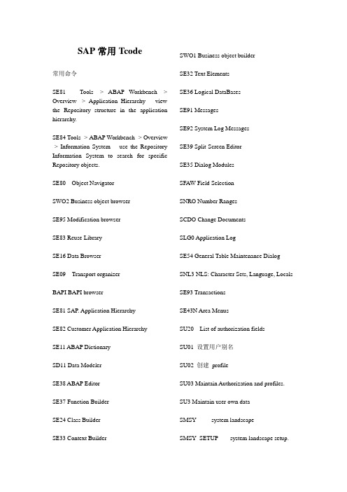
SAP常用Tcode常用命令SE81 Tools -> ABAP Workbench -> Overview -> Application Hierarchy view the Repository structure in the application hierarchy.SE84 Tools -> ABAP Workbench -> Overview -> Information System use the Repository Information System to search for specific Repository objects.SE80 Object NavigatorSWO2 Business object browserSE95 Modification browserSE83 Reuse LibrarySE16 Data BrowserSE09 Transport organizerBAPI BAPI browserSE81 SAP. Application HierarchySE82 Customer Application HierarchySE11 ABAP DictionarySD11 Data ModelerSE38 ABAP EditorSE37 Function BuilderSE24 Class BuilderSE33 Context Builder SWO1 Business object builderSE32 Text ElementsSE36 Logical DataBasesSE91 MessagesSE92 System Log MessagesSE39 Split-Screen EditorSE35 Dialog ModulesSFAW Field SelectionSNRO Number RangesSCDO Change DocumentsSLG0 Application LogSE54 General Table Maintenance Dialog SNL3 NLS: Character Sets, Language, Locals SE93 TransactionsSE43N Area MenusSU20 List of authorization fieldsSU01 设置用户别名SU02 创建profileSU03 Maintain Authorization and profiles. SU3 Maintain user own dataSMSY system landscapeSMSY_SETUP system landscape setup.PFCG 维护用户权限信息RMMain RoadMap的主信息SE06 Post-Installation for Transport OrganizerSLICENSE or SLIC 激活SAP license。


Issue: 02Part Number: 31508726Date: 2018-03-15SU2000L-(3KTL, 4KTL, 5KTL)-CN Quick Guide1Overview(1) LED (2) Front panel(3) Mounting plate (4) Mounting bracket(5) Heat sink (6) DC switch (DC SWITCH)(7) Ventilation valve (8) DC input terminals (PV+/PV –)(9) COM port (COM)(10) Antenna port (ANT)(11) Ground point(12) AC output port (AC)(13) USB-4G port cover (USB-4G)2Installing the DeviceInstallation Requirements2.1DimensionsTilt and Space1.The information in this document is subject to change without notice. Every effort has been made in the preparation of this d ocument to ensure accuracy of the contents, but all statements, information, and recommendations in this document do not constitute a warranty of any kind, express or implied.2.Before installing the device, closely read the user manual to get familiar with product information and safety precautions.3.Only certified electricians are allowed to operate the device. Operation personnel must wear proper personal protective equip ment (PPE) all the time.4.Before installing the device, check that the package contents are intact and complete against the packing list. If any damageis found or any component is missing, contact your supplier.5.Huawei shall not be liable for any consequence caused by violation of the storage, transportation, installation, and operation regulations specified in this document and the user manual.NOTICEFor the model without an external WiFi antenna, the antenna port (ANT) is actually a cover and there is no port inside.NOTEIf multiple inverters need to be installed, see SUN2000L-(3KTL, 4KTL, 5KTL)-CN User Manual for the installation dimensions.NOTESupport-mounted InstallationYou are advised to apply anti-rust paint on the hole positions for protection.Prepare M8 stainless bolt assemblies (including flat washers, spring washers, and M8 bolts) with appropriate lengths as well as matched flat washers and nuts based on the support specifications.Installing the Mounting Bracket2.2Copyright © Huawei Technologies Co., Ltd. 2018. All rights reserved.Installing the SUN2000L2.31.Install the SUN2000L on the mounting bracket.2.Tighten screw assemblies.3.(Optional) Install an anti-theft lock.●If the bottom of themounting plate does not snap into place, push the SUN2000L from the front until the bottom of the mounting plate snaps into the mounting bracket.●The anti-theft lock needs to be prepared by the customer.NOTICE(Optional) Installing the 4G Module2.4(Optional) Installing the WiFi Antenna2.5NOTICE●If the 4G module has a built-in SIM card, there is no need to install a SIM card.●After installed and powered on, the 4G module can access the network without being commissioned.●The USB-4G port is available only for a 4G module, rather than a USB data cable.●Install the SIM card in the direction shown by the silk screen and arrow on the slot.●Press the SIM card until it snaps into place and locked, which means that the SIM card is installed correctly.●To remove the SIM card, push it inwards. The SIM card will spring out automatically.●Ensure that the WiFi antenna is installed securely. ●The 4G module and WiFi antenna cannot be used at the same time.NOTICE3Connecting CablesPreparing Cables3.1Prepare cables based on site requirements.No.Cable Type Conductor Cross-sectional Area RangeOuter Diameter 1PE cable Single-core outdoor copper cable4–6 mm 2N/A 2AC output power cableTwo-core (L and N) outdoor copper cable or three-core (L, N, and PE) outdoor copper cable 4–6 mm 210–21 mm 3DC input power cableStandard outdoor PV cable in the industry(recommended model: PV1-F)4–6 mm 2 4.5–7.8 mm 4Signal cable (optional)Outdoor shielded twisted pair0.25–1 mm 24–11 mm●Connect cables in accordance with the installation laws and regulations of the country or region where the project is located.●The PE point at the AC output port is used only as a PE equipotential point, and cannot substitute for the PE point on the enclosure.●Before connecting cables, ensure that the DC switch on the SUN2000L and all the switches connecting to the SUN2000L are OFF. Otherwise, the high voltage of the SUN2000L may result in electric shocks.NOTICEReinstalling the 4G module enclosure, ensure that the buckle springs back to the original position.Avoid drilling holes in the utility pipes and/or cables attached to the back of the wall.Wall-mounted InstallationDANGERInstalling the PE Cable3.2Do not connect the neutral wire to the enclosure as a PE cable. Otherwise, electric shocks will be caused.●Recommended: Apply silica gel or paint around a ground terminal after connecting the ground cable.●The PE point at the AC output port is used only as a PEequipotential point, and cannot substitute for the PE point on the enclosure.DANGERNOTEInstalling the AC Output Power Cable3.3Ensure that the exposed core wire is totally inserted into the cable hole and connected securely. Failing to do so may cause SUN2000L malfunction and damage.NOTICE1.Connect the AC output power cable to the AC connector.Three-Core Cable (L, N, and PE)Two-Core Cable (L and N)Installing the DC Input Power Cable3.42.Connect the AC connector to the AC output port.NOTETo remove the AC connector from the SUN2000L, perform the operations in reverse order. The right figure shows how to remove a plug insert.ClickClick3.Check the route of the AC output power cable.Positive connectorNegative connectorPositive metal terminalNegative metal terminalEnsure that the cable will not be extracted after crimped.Ensure that the locking nut is secured.Ensure that the cables are correctly connected.Pull the DC input power cable back to ensure that it is connected securely.Pull the DC input power cable back to ensure that it is connected securely.ClickPositive connectorNegative connectorPositive metal terminalNegative metal terminalEnsure that the cable will not be extracted after crimped.Ensure that the locking nut is secured.Ensure that the cables are correctly connected.Pull the DC input power cable back to ensure that it is connected securely.using metal cold forming contactsusing metal stamping forming contacts1.Assembling the DC Connector2.Connecting the DC Input Power Cable1.Ensure that the PV string is well insulated to ground.2.The metal contacts supplied with the DC connectors are either cold forming contacts orstamping forming contacts. Crimp the metal cold forming contacts using crimping tool H4TC0001 (Amphenol). Crimp the metal cold stamping contacts using crimping toolH4TC0002 (Amphenol). Choose the crimping tools that fit the metal contact types. Do not mix up the tools.3.The SUN2000L DC input voltage must always be lower than or equal to 600 V DC.4.Before installing the DC input power cable, label the cable polarities correctly to ensurecorrect cable connections.e the positive and negative connectors supplied with the SUN2000L.6.If polarity of the DC input power cable is reversed and the DC switch is ON, do not turn offthe DC switch immediately or unplug positive and negative connectors. The device may be damaged if you do not follow the instruction. This damage is not covered under anywarranty or service agreement. Wait until the solar irradiance declines at night and the PV string current reduces to below 0.5 A, and then turn off the DC switch and remove the positive and negative connectors. Correct the string polarity before reconnecting the string to the SUN2000L.NOTICE(Optional) Installing the RS485 Communications Cable3.5●When laying out communications cables, separate them from power cables to avoid strong signal interference sources.●Ensure that the exposed core wire is totally inserted into the cable hole and connected securely.NOTICEbel Definitionbel Definition1485B1RS485B, RS485 differential signal –2485A1RS485A, RS485 differential signal+3485B2RS485B, RS485 differential signal –4485A2RS485A, RS485 differential signal+512V –Negative of the 12 V powersupply (reserved, power ≤ 3 W)612V+Positive of the 12 V powersupply (reserved, power ≤ 3 W)7N/AN/A8PEGrounding the shield layer●If only one signal cable needs to be connected, block the unused cable hole on the seal using a cap and tighten the cable gland. ●If two signal cables are required, ensure that they have the same outer diameter.NOTICE4Verifying the Installation5Powering On the SystemNo.Acceptance Criteria1The SUN2000L is installed correctly, securely, and reliably.2The WiFi antenna or 4G module is installed correctly, securely, and reliably.3Cables are routed properly as required by the customer.4Cable ties are secured evenly and no burr exists.5The ground cable is connected correctly, securely, and reliably.6The DC switch and all the switches connecting to the SUN2000L are OFF.7The AC output power cable, DC input power cable, and signal cable are connected correctly, securely, and reliably.8Unused terminals and ports are locked by watertight caps.9The installation space is proper, and the installation environment is clean and tidy, without foreign matter.Before turning on the AC switch between the SUN2000L and the power grid, check that the AC voltage on the power grid side of the AC switch is within the specified range.1.Turn on the AC switch between the SUN2000L and the power grid.2.Turn on the DC switch between the PV string and the SUN2000L if there is any.3.Turn on the DC switch at the bottom of the SUN2000L.4.Perform quick setting over the app by referring to the SUN2000L App Quick Guide .5.(Optional) Measure the temperatures at the joints between the DC terminals and the connectors using a point-test thermometer.6.Observe the LEDs to check the SUN2000L operating status.NOTICEHuawei Technologies Co., Ltd.Huawei Industrial Base, Bantian, Longgang Shenzhen 518129 People's Republic of China Type Status (Blinking at LongIntervals: On for 1s and thenOff for 1s; Blinking at Short Intervals: On for 0.2s and then Off for 0.2s)MeaningRunning indication LED1LED2N/A Steady green Steady green The SUN2000L isexporting power to the power grid.Blinking greenat long intervalsOff The DC is on and the AC is off.Off Blinking greenat long intervalsThe DC is off and the AC is on.Blinking green at long intervals Blinking greenat long intervalsThe DC is on and the AC is on.The SUN2000L is not exportingpower to the power grid.Off Off The DC is off and the AC is offor the SUN2000L is in lowpower consumption mode.Steady red Steady red The SUN2000L is faulty.Communication indication LED3N/A Blinking green at short intervalsThe SUN2000L is incommunication.Blinking green at long intervalsThe SUN2000L has connectedto the mobile phone.Off No communicationLED1LED2LED3StatusMeaningBlinking: The period is 2s. The LED is on for 0.1s, then off for 0.1s, then on for 0.1s, and finally off for 1.7s.No service is provided or the service is limited.Blinking: The period is 2s. The LED is on for 0.1s and then off for 1.9s.The SUN2000L has connected to the network.Steady onThe SUN2000L is in communication.7.If a 4G module is installed, wait for about 15 seconds for dialup after the inverter is powered on. Then observe the LED indicator on the 4G module to check the module status.Under normal operation conditions of the SUN2000L, the temperature rise at DC connectors should remain below 40°C at all time.NOTECustomer Service Contact Information Region Country Service Support Mailbox China China ***********************IndiaIndia ******************************Japan and Korea Japan andSouth Korea **********************.com EuropeAll countries******************************North AmericaThe United States and Canada ******************************Latin America All countries ******************************Asia PacificAustralia******************************Other countries ***************************The Middle East and AfricaAll countries *******************************。


su03t手册
【原创版】
目录
1.SU03T 手册概述
2.SU03T 手册的内容
3.SU03T 手册的使用方法
4.SU03T 手册的适用对象
5.SU03T 手册的价值
正文
SU03T 手册是一款全面的指南,旨在帮助用户更好地理解和使用相关产品。
本文将详细介绍 SU03T 手册的内容、使用方法、适用对象以及其价值。
一、SU03T 手册概述
SU03T 手册是一款详细阐述 SU03T 产品的使用说明,它包含了产品的基本信息、功能介绍、操作指南等,是用户了解和使用 SU03T 产品的重要参考资料。
二、SU03T 手册的内容
SU03T 手册的内容主要包括以下几个方面:
1.产品简介:介绍产品的基本信息,如名称、型号、功能等;
2.功能介绍:详细阐述产品的各项功能,以及如何使用这些功能;
3.操作指南:提供详细的操作步骤,帮助用户顺利完成各项任务;
4.维护与保养:介绍产品的维护和保养方法,以延长产品使用寿命;
5.故障排除:提供常见故障的排查方法,帮助用户解决使用过程中遇
到的问题。
三、SU03T 手册的使用方法
1.首先,用户需要认真阅读手册中的内容,了解产品的基本信息和功能;
2.在使用产品时,按照手册中的操作指南进行操作;
3.如果遇到问题,可以查阅手册中的故障排除部分,寻找解决方案;
4.平时使用过程中,可以根据手册中的维护与保养建议,对产品进行维护和保养。
四、SU03T 手册的适用对象
SU03T 手册适用于购买 SU03T 产品的所有用户。
无论您是初次使用者还是资深用户,都可以从手册中获取有关产品的详细信息,从而更好地使用产品。
五、SU03T 手册的价值
SU03T 手册具有很高的实用价值,它可以帮助用户更好地了解产品,提高使用效率,降低故障率,延长产品使用寿命。
同时,它也可以为用户提供专业的技术支持,让用户在使用过程中更加安心。