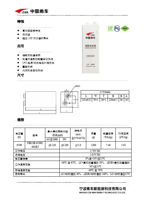
超级电容规格书--BRP002R8L224FA(2.8V 0.22)
- 格式:pdf
- 大小:655.25 KB
- 文档页数:7
超级电容参数超级电容,也称为超级电容器,是一种新型电化学储能设备,它具有非常优越的性能特点。
超级电容器可实现高能量密度、高功率密度、长寿命、高可靠性等特点,无污染、绿色环保。
其在电动汽车、可再生能源等领域有着广泛的应用前景。
超级电容的参数有很多,而其中最重要的就是电容量和电压。
电容量指的是超级电容器存储电荷的能力,通常用单位法拉(F)表示,其数值范围可以从数微法到数万法之间。
而另一个主要的参数是电压,通常用伏特(V)表示。
高电压可带来更高的储能密度,但也会增加超级电容器的成本和材料需求。
与传统电容器比较,超级电容的电压较高,而电容量相对较小,这使得它们可以提供高功率输出,通常用于短时间的能量储存和释放。
具体来说,超级电容可以带来很高的放电电流(通常可达数百安培),从而适用于高强度应用,如汽车动力系统、光伏及风力发电储能系统等。
除了电容量和电压,超级电容器的导电性、电解质、电极材料等参数也非常重要。
导电性可影响超级电容器的内阻和热效应,电解质的化学稳定性、电极材料的表面积等都会对超级电容的性能造成影响。
为了获得最佳的超级电容器性能,人们需要在多个参数之间进行平衡和优化。
例如,提高超级电容器的电容量需要增加电极表面积和电解质浓度,这可能会导致超级电容器的内阻增加;而提高超级电容器的电压需要增加电极间距和跨越电介质厚度,这会增加电容器的尺寸和成本。
总之,超级电容器是一种具有高性能和广泛应用前景的电化学储能设备,其性能与多个参数密切相关。
优化超级电容器的参数,将有助于提高其电荷/放电特性、能量密度和循环寿命,并促进其在许多领域的广泛应用。
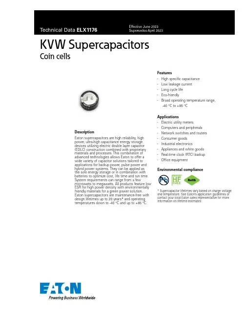
Environmental complianceKVW SupercapacitorsCoin cellsDescriptionEaton supercapacitors are high reliability, high power, ultra-high capacitance energy storage devices utilizing electric double layer capacitor (EDLC) construction combined with proprietary materials and processes. This combination of advanced technologies allows Eaton to offer a wide variety of capacitor solutions tailored to applications for backup power, pulse power and hybrid power systems. They can be applied as the sole energy storage or in combination with batteries to optimize cost, life time and run time. System requirements can range from a fewmicrowatts to megawatts. All products feature low ESR for high power density with environmentally friendly materials for a green power solution. Eaton supercapacitors are maintenance-free with design lifetimes up to 20 years* and operating temperatures down to -40 °C and up to +85 °C.Features• High specific capacitance • Low leakage current • Long cycle life • Eco-friendly•Broad operating temperature range,-40 °C to +85 °CApplications• Electric utility meters •Computers and peripherals • Network switches and routers • Consumer goods • Industrial electronics • Appliances and white goods • Real-time clock (RTC) backup •Office equipmentPb HALOGENHF FREE* Supercapacitor lifetimes vary based on charge voltage and temperature. See Eaton’s application guidelines or contact your local Eaton sales representative for more information on lifetime estimates2Technical Data ELX1176Effective June 2023KVW SupercapacitorsCoin cells/electronicsRatings 10Capacitance0.68 F to 1.0 F Maximum working voltage 5.0 V Surge voltage 95.5 VCapacitance tolerance -20% to +80% (+20 °C)Operating temperature range-40 °C to +85 °CSpecificationsCapacitance (F)Part numberMaximum initial ESR 1 +25 °C (Ω)Nominal leakage current 1,2 (µA)Stored energy 3 (mWh)Peak power 4 (W)Pulsecurrent 5 (A)Shortcircuit current 6(A)0.68KVW-5R0C684-R 3010 2.360.2080.0790.1671.0KVW-5R0C105-R30103.470.2080.0810.167PerformanceParameterCapacitance change (% of initial value)ESR(% of maximum initial value)Lifetime: (1000 hours at +85 °C, 5.0 V)≤ 30%≤ 200%Storage: life (1000 hours ,-40 °C to +85 °C)≤ 30%≤ 200%1. Capacitance, Equivalent Series Resistance (ESR) and Leakage current are measured according to IEC62391-1 with current in milliamps (mA) = 8 x C x V.2. Leakage current at +25 °C after 24 hour charge and hold.3. Stored Energy (mWh) = 0.5 x C x V 2 36004. Peak Power (W) = V 2 4 x ESR5. Pulse current for 1 second from full rate voltage to half voltage.(A) = 0.5 x V x C (1 + ESR x C)6. Short circuit current is for safety information only. Do not use as operating current.7. Testing and verification of product under end application conditions is recommended8. Not recommended for +85 °C/85% RH applications9. Surge voltage: Maximum voltage, non-repetitive, 1 second maximum.Safety and certificationsEnvironmental compliance and general specifications RoHS, REACH, Halogen free Shock and vibration MIL-STD 202GWarnings Do not overvoltage, do not reverse polarityShippingNo restrictions, per UN3499 with all cells <0.3 watt-hoursx 10003Technical Data ELX1176Effective June 2023KVW Supercapacitors Coin cells /electronics Dimensions (mm) and mass (g)Part numberOD ±0.5H ±0.5L(-) ±0.5L(+)±0.5P ±0.5T ±0.1L1±0.3L2±0.3W ±0.2W1±0.2Mass (typical)KVW-5R0C684-R 20.810.5 5.8 5.5 5.50.5 3.3 3.80.8 1.212.2KVW-5R0C105-R20.810.55.85.55.50.53.33.80.81.212.6Part numbering systemPackaging information• Bulk--100 parts per tray, 500 parts per box• • •Part marking• Eaton logo• Capacitance value (F) • Operating voltage (V) •Polarity markEatonElectronics Division 1000 Eaton Boulevard Cleveland, OH 44122United States/electronics © 2023 EatonAll Rights Reserved Printed in USAPublication No. ELX1176 June 2023KVW SupercapacitorsCoin cellsTechnical Data ELX1176Effective June 2023Life Support Policy: Eaton does not authorize the use of any of its products for use in life support devices or systems without the express writtenapproval of an officer of the Company. Life support systems are devices which support or sustain life, and whose failure to perform, when properly used in accordance with instructions for use provided in the labeling, can be reasonably expected to result in significant injury to the user.Eaton reserves the right, without notice, to change design or construction of any products and to discontinue or limit distribution of any products. Eaton also reserves the right to change or update, without notice, any technical information contained in this bulletin.T e m p e r a t u r eTimeT T T TWave solder profileEaton is a registered trademark.All other trademarks are property of their respective owners.Follow us on social media to get the latest product and support information.Profile FeatureStandard SnPb SolderLead (Pb) Free SolderPreheat and soak • Temperature max. (T smax )100 °C 100 °C • Time max.60 seconds 60 seconds D preheat to max temperature160 °C max.160 °C max.Peak temperature (T P )*220 °C – 260 °C 250 °C – 260 °C Time at peak temperature (t p ) 5 seconds max 5 seconds max Ramp-down rate~ 2 K/s min~3.5 K/s typ ~5 K/s max ~ 2 K/s min ~3.5 K/s typ ~5 K/s max Time 25 °C to 25 °C4 minutes4 minutesManual solderDo not touch the supercapacitor’s external sleeve with the soldering rod or the sleeve will melt or crack. The recommended temperature of the soldering rod tip is less than +360 °C and the soldering duration should be less than 5 seconds. Minimize the time that the soldering iron is in direct contact with the terminals of the supercapacitor as excessive heating of the leads may lead to higher equivalent series resistance (ESR). Generally manual soldering is not recommended..Reflow solderingDo not use reflow soldering using infrared or convection oven heating methods.Cleaning/WashingAvoid cleaning of circuit boards, however if the circuit board must be cleaned use static or ultrasonic immersion in a standard circuit board cleaning fluid for no more than 5 minutes and a maximum temperature of +60 °C. Afterwards thoroughly rinse and dry the circuit boards. In general, treat supercapacitors in the same manner you would an aluminum electrolytic capacitor.WARNING: DO NOT EXCEED +100 °C BODY T EMPERATURE. PERMANENT DAMAGE MAY OCCUR。
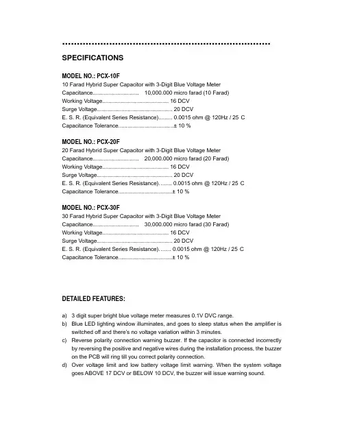
....................................................................... SPECIFICATIONSMODEL NO.: PCX-10F10 Farad Hybrid Super Capacitor with 3-Digit Blue Voltage Meter Capacitance.............................. 10,000.000 micro farad (10 Farad)Working Voltage........................................... 16 DCVSurge Voltage................................................. 20 DCVE. S. R. (Equivalent Series Resistance)......... 0.0015 ohm @ 120Hz / 25°CCapacitance Tolerance....................................± 10 %MODEL NO.: PCX-20F20 Farad Hybrid Super Capacitor with 3-Digit Blue Voltage Meter Capacitance.............................. 20,000.000 micro farad (20 Farad)Working Voltage........................................... 16 DCVSurge Voltage................................................. 20 DCVE. S. R. (Equivalent Series Resistance)…..... 0.0015 ohm @ 120Hz / 25°CCapacitance Tolerance...................................± 10 %MODEL NO.: PCX-30F30 Farad Hybrid Super Capacitor with 3-Digit Blue Voltage Meter Capacitance.............................. 30,000.000 micro farad (30 Farad)Working Voltage........................................... 16 DCVSurge Voltage................................................. 20 DCVE. S. R. (Equivalent Series Resistance)……. 0.0015 ohm @ 120Hz / 25°CCapacitance Tolerance...................................± 10 %DETAILED FEATURES:a) 3 digit super bright blue voltage meter measures 0.1V DVC range.b) Blue LED lighting window illuminates, and goes to sleep status when the amplifier isswitched off and there’s no voltage variation within 3 minutes.c) Reverse polarity connection warning buzzer. If the capacitor is connected incorrectlyby reversing the positive and negative wires during the installation process, the buzzer on the PCB will ring till you correct polarity connection.d) Over voltage limit and low battery voltage limit warning. When the system voltagegoes ABOVE 17 DCV or BELOW 10 DCV, the buzzer will issue warning sound.INSTALLATION AND MOUNTING:Securely mount the capacitor using supplied hardware. Be careful when choosing mounting location to avoid moving parts and possible exposure to moisture.CHARGING THE CAPACITOR AND WIRING:The capacitor must be charged before connecting the Power and Ground cables to the capacitor. Failure to charge the capacitor will result in a large spark generated from the rapid inflow of current.1. To charge the capacitor:Make capacitor positive terminal connections with amplifier and tighten the bolt. Do not over-tighten the bolt!Caution: Stripped terminals are not covered under the capacitor’s warranty.2. Connect the ground cables of the battery, amplifier, and capacitor separately tochassis.3. Place the supplied charging resistor between the positive terminal of the capacitor andthe battery’s positive terminal. After 5~60 seconds, the capacitor will be fully charged.Caution: The resistor will become hot!4. Immediately after the charging process, take away the charging bulb from theconnecting wire, and connect the positive cable to the positive terminal on the capacitor.CAPACITOR WIRING DIAGRAM:DISCHARGING THE CAPACITOR:Never remove the capacitor without discharging the stored power – it can give adangerous electrical shock!To disconnect the capacitor, follow these instructions:1. Disconnect the cables from the capacitor in the following order:a) positive (+) cableb) ground (-) cable2. Holding the resistor provided, touch the leads to the positive (+) and ground (-)terminals of the capacitor. After 1~5 minutes, the capacitor will be discharged (Thecharging resistor will become hot!) Then you can safely remove and handle it.WARNING!!THIS POWER CAPACITOR MAY EXPLODE AND CAUSE SERIOUS INJURY IF ABUSEDOR CONNECTED IMPROPERLY. PLEASE REFER TO THE INSTRUCTIONS CONTAINEDIN THIS MANUAL FOR CORRECT OUNTING, CHARGING/DISCHARGING AND WIRINGCONNECTION FOR THIS CAPAPCITOR PRIOR TO INSTALLATION.POWER ACOUSTIK AUDIO ACCESSORIES CAR AUDIO ACCESSORIES。
超级电容基本参数概念超级电容器(Supercapacitors,ultracapacitor),又名电化学电容器(ElectrochemicalCapacitors),双电层电容器(ElectricalDoule-LayerCapacitor)、黄金电容、法拉电容,是从上世纪七、八十年代发展起来的通过极化电解质来储能的一种电化学元件。
以下是店铺分享给大家的关于超级电容基本参数概念,欢迎大家前来阅读!超级电容基本参数概念:超级电容器具有比二次电池更长的使用寿命,但它的使用寿命并不是无限的,超级电容器基本失效的形式是电容内阻的增加( ESR)与(或) 电容容量的降低.,电容实际的失效形式往往与用户的应用有关,长期过温(温度)过压 (电压),或者频繁大电流放电都会导致电容内阻的增加或者容量的减小。
在规定的参数范围内使用超级电容器可以有效的延长超级电容器的寿命。
通常,超级电容器具有于普通电解电容类似的结构,都是在一个铝壳内密封了液体电解液,若干年以后,电解液会逐渐干涸,这一点与普通电解电容一样,这会导致电容内阻的增加,并使电容彻底失效。
一、电压 Voltage超级电容器具有一个推荐的工作电压或者最佳工作电压,这个值是根据电容在最高设定温度下最长工作时间来确定的。
如果应用电压高于推荐电压,将缩短电容的寿命,如果过压比较长的时间,电容内部的电解液将会分解形成气体,当气体的压力逐渐增强时,电容的安全孔将会破裂或者冲破。
短时间的过压对电容而言是可以容忍的。
二、极性 Polarity超级电容器采用对称电极设计,也就说,他们具有类似的结构。
当电容首次装配时,每一个电极都可以被当成正极或者负极,一旦电容被第一次100%从满电时,电容就会变成有极性了,每一个超级电容器的外壳上都有一个负极的标志或者标识。
虽然它们可以被短路以使电压降低到零伏,但电极依然保留很少一部分的电荷,此时变换极性是不推荐的。
电容按照一个方向被充电的时间越长,它们的极性就变得越强,如果一个电容长时间按照一个方向充电后变换极性,那么电容的寿命将会被缩短。
今朝时代超级电容说明书
超级电容器(Supercapacitors,ultracapacitor),又名电化学电容器(ElectrochemicalCapacitors),双电层电容器(ElectricalDoule-LayerCapacitor)、黄金电容、法拉电容,是从上世纪七、八十年代发展起来的通过极化电解质来储能的一种电化学元件。
它不同于传统的化学电源,是一种介于传统电容器与电池之间、具有特殊性能的电源,主要依靠双电层和氧化还原假电容电荷储存电能。
但在其储能的过程并不发生化学反应,这种储能过程是可逆的,也正因为此超级电容器可以反复充放电数十万次。
其基本原理和其它种类的双电层电容器一样,都是利用活性炭多孔电极和电解质组成的双电层结构获得超大的容量。
他的突出特点是充电速度快,充电10秒~10分钟可达到其额定容量的95%以上;环使用寿命长,深度充放电循环使用次数可达1~50万次,没有“记忆效应”;大电流放电能力超强,能量转换效率高,过程损失小,大电流能量循环效率≥90%;功率密度高,可达
300W/KG~5000W/KG,相当于电池的5~10倍;产品原材料构成、生产、使用、储存以及拆解过程均没有污染,是理想的绿色环保电源;充放电线路简单,无需充电电池那样的充电电路,安全系数高,长期使用免维护;超低温特性好,温度范围宽-40℃~+70℃;检测方便,剩余电量可直接读出;容量范围通常0.1F--1000F。
超级电容的规格超级电容是一种具有高电容量和高储能密度的电子元件,它在电能存储和释放方面具有很多优势。
本文将从超级电容的规格参数入手,介绍超级电容的特点、应用以及未来发展方向。
一、额定电压超级电容的额定电压是指超级电容器可以长时间工作的电压范围。
超级电容的额定电压通常在2.5V到5.5V之间,具体取决于超级电容的结构设计和材料选择。
超级电容的额定电压较低,这使得它在一些低压应用中具有优势,例如备用电源、电动车辆的启动系统等。
二、容量超级电容的容量是指超级电容器可以存储的电荷量。
超级电容的容量通常以法拉(F)为单位,容量大小一般在几毫法拉至几千法拉之间。
相比于传统电容器,超级电容具有更高的电容量,可以储存更多的电荷。
因此,超级电容在能量存储和释放方面具有较大优势。
三、内阻超级电容的内阻是指在超级电容器工作时电流通过的阻力。
内阻的大小直接影响超级电容的充放电效率和功率输出能力。
一般来说,超级电容的内阻较低,这使得它可以快速充放电,适用于需要高功率输出的应用,如电动车辆的刹车能量回收系统。
四、寿命超级电容的寿命是指超级电容器可以正常工作的时间。
超级电容的寿命主要取决于电解液的稳定性和超级电容器内部的电化学反应。
一般来说,超级电容的寿命较长,可以达到几万个充放电循环。
这使得超级电容在需要长寿命和高可靠性的应用中具有优势,如可穿戴设备、智能电表等。
五、温度范围超级电容的温度范围是指超级电容器可以正常工作的温度范围。
超级电容的温度范围通常在-40℃到+85℃之间,具体取决于超级电容的材料和封装方式。
超级电容具有较好的耐温性能,可以在较宽的温度范围内工作,适用于各种环境条件下的应用,如电动车辆、太阳能储能系统等。
超级电容作为一种新型的电子元件,在能量存储和释放方面具有广泛的应用前景。
目前,超级电容已经在汽车、电子设备、可再生能源等领域得到了广泛应用。
未来,随着超级电容技术的不断发展,超级电容的容量将进一步提升,其在能量存储领域的应用将更加广泛。
超级电容器简介超级电容器简介超级电容器事业部 20111213Lishen Battery Joint-Stock Co., Ltd. Proprietary Confidential目录:第一章:电容器第二章:超级电容器2.1 超级电容器定义 2.2 超级电容器储能原理 2.3 超级电容器特性2.4 公司现有产品图 2.5 超级电容器应用第三章:总结Lishen Battery Joint-Stock Co., Ltd. Proprietary Confidential第一章:电容器基本知识1.1 电容器定义:电容器是由两片接近并相互绝缘的导体制成的电极组成的储存电荷和电能的器件,英文名称:capacitor。
电容定义:电容是表征电容器容纳电荷本领的物理量。
电容器的电容量可用每伏特储存的电荷量表示,用字母C表示,单位是法拉(F)。
备注:电池容量表示的是法拉第电荷储存的多少,单位是库伦(A.S)或 mAh。
Lishen Battery Joint-Stock Co., Ltd. Proprietary Confidential1.2 电容计算公式:电容器容量计算公式:C=Q/U, C单位法拉(F),Q是库伦(A.S),U单位是伏特(V). 电容所储存的电能: E=(UC/3600)Ah =(CU2/2/3600)wh 电容的基本单位是法拉(F),其它单位还有:毫法(mF)、微法(uF)、纳法(nF)、皮法(pF)。
单位换算关系:1F=1000mF 1μF=1000nF1mF=1000μF 1nF=1000pFLishen Battery Joint-Stock Co., Ltd. Proprietary Confidential1.3电容器分类电解电容器陶瓷电容器普通电容器薄膜电容器云母电容器微调电容器碳碳双电层电容器电容器超级电容器氧化物/碳混合电容器赝电容器(法拉第准电容器)Lishen Battery Joint-Stock Co., Ltd. Proprietary Confidential第二章:超级电容器介绍2.1 超级电容器定义:超级电容器,英文Ultracapacitor 或supercapacitor,就是超大容量的电容器,其容量都是法拉级,一般情况下容量范围可达1F-5000F,有的甚至上万及法拉,而普通电容器都是PF或μF级。
iec 超级电容-概述说明以及解释1.引言1.1 概述超级电容(Super Capacitor)是一种新型的能量存储装置,它介于传统电容和化学电池之间。
相对于传统电容器,超级电容具有更高的能量密度和更大的功率密度,可以在短时间内快速充放电。
与传统化学电池相比,超级电容具有更长的循环寿命和更高的可靠性。
超级电容器的工作原理是通过在两个电极之间形成一个电介质,来存储电荷。
与传统电容器不同的是,超级电容器使用高表面积的电极材料,如活性炭或金属氧化物,来增加存储电荷的能力。
同时,电介质的选择也非常重要,它需要具有较高的介电常数和低电阻,以便快速存储和释放电荷。
超级电容器在多个领域都有广泛的应用。
在电动车领域,超级电容器可以用作辅助能量源,提供高效稳定的瞬时功率输出,以增加车辆的加速性能和能量回收效率。
在可再生能源领域,超级电容器可以作为储能设备,平衡能量的供需差异。
此外,超级电容器还被广泛应用于电子设备、电网稳定、医疗器械等领域。
尽管超级电容器具有很多优势,如高速充放电、长循环寿命和可靠性,但也存在一些局限性。
首先,超级电容器的能量密度较低,无法与化学电池相比。
其次,超级电容器的成本较高,限制了其大规模商业应用。
此外,超级电容器的稳定性和耐高温性还需要进一步改进。
总结而言,超级电容作为一种新兴的能量存储装置,具有重要的应用前景。
随着技术的不断创新和进步,超级电容器的能量密度和成本将不断提高,其在电动交通、可再生能源和其他领域的应用将会进一步扩大。
因此,超级电容器在能源存储领域的发展有着巨大的潜力。
文章结构部分的内容应包括对整篇文章的组织和结构进行说明。
下面是一个可能的编写示例:1.2 文章结构本文将按照以下结构进行叙述:1.引言:概述超级电容的定义、原理和应用背景,介绍文章的目的。
2.正文:2.1 超级电容的定义和原理:详细介绍超级电容的基本概念、组成结构和工作原理。
将对超级电容与传统电容的区别进行分析,并阐述其高能量密度和长寿命的特点。
WRITTEN CHECKED APPROVEDTo. : DATE : 200 . . .SPECIFICATIONPRODUCT : STARCAPMODEL : DMS seriesKORCHIP CORP.KORCHIP B/D, 817-38, Anyang 2-dong, Manan-gu, Anyang-si, Gyeonggi-do, KOREA TEL : 82 - 31 - 361 - 8000 FAX : 82 - 31 - 361 - 8080Page No.ITEM etc.1Cover Page2Index3 1. Scope2. Part Number System3. Product Model Name4. Photo5. Nominal Specifications4 6. Cell Structure7. Product Construction And Dimension5 8. Packing Specifications6 9. Specifications And Test Method7 10. Measuring Method Of Characteristics8 11. Mounting And Soldering9 12. Cautions For Use10 13. Environmental ManagementIndexItems DMS 3R3 204 R DMS 3R3 224 R Cell SizeØ6.8 × 1.4mm Ø6.8 × 1.4mm OPERATING TEMPERATURE-10 ~ +60 ℃-10 ~ +60 ℃RATED VOLTAGE3.3 VDC 3.3 VDC ELECTROSTATIC CAPACITANCE (F)0.20 F 0.22 F CAPACITANCE TOLERANCE -20 ~ 80 %-20 ~ 80 %EQUIVALENT SERIES RESISTANCE (ESR)LESS THAN 200ΩLESS THAN 200ΩLEAKAGE CURRENT (LC)LESS THAN 150㎂LESS THAN 150㎂1. ScopeThis specification applies to STARCAP(Electric Double Layer Capacitor), submitted to specified customer in cover page.2. Part Number SystemDMS 3R3 204 R (Example)① ② ③ ④① Series Name② Rated Voltage : 3.3VDC③ Capacitance : 0.20 F (204 = 20 × 10+4uF) ④ Terminal Type : R-type3. Product Model Name1) Product : Electric Double Layer Capacitor 2) Model name : DMS3R3204R, DMS3R3224R4. Photo5. Nominal SpecificationsPart Number Dimension (mm)ØD H DMS 3R3 204 R 6.8 Max 1.8 Max DMS 3R3 224 R6.8 Max1.8 Max6. Cell Structure7. Product Construction And DimensionPRODUCTQUANTITY(PCS)SIZE(WxLxH mm)Weight(Kg) Tray Inner Box Outer Box Inner Box Outer BoxDMS 3R3 204 R1001,00016,000180×170×75375×340×350≃ 9 DMS 3R3 224 R1001,00016,000180×170×75375×340×350≃ 9 8. Packing Specification9. Specifications And Test Method10. Measuring Method Of CharacteristicsE0 : VdcR C : 100Ω11. Mounting And SolderingWhen you solder DMS series STARCAP to a printed circuit board, excessive thermalstress could cause the STARCAP's electrical characteristics to deteriorate, compromisethe integrity of the seal or cause the electrolyte to leak due to increased internal pressure.① Recommended condition of mountingIf you want to set or mount DMS series STARCAP on a PCB with resin before soldering for ease of soldering process, follow the thermal condition below.- Hardening Temp. of Resin : 80℃ or below- Hardening Time of Resin : 10 min. or less② Recommended condition of soldering- Soldering Tip Temp. : 350℃ or below- Soldering Time : 3 sec. or less- Times : Three times or less at intervals of 9 sec. or more※ Do not touch the metal case of STARCAP with a soldering iron.③ It is not allowed to go through flow or reflow(IR, Atmosphere heating methodsetc.) process.④ The terminals are plated for good solderability. Rasping terminals may damage the plating layer and degrade the solderability.Do not apply a large force to the terminals. Otherwise, they may break or come off or the STARCAP characteristics may be deteriorated.12. Cautions For UsePlease be careful for following points when you use STARCAP.1) Do not apply more than rated voltage.If you apply more than rated voltage, STARCAP's electrolyte will be electrolyzed and itsESR increase. At the worst, it may be broken.2) Do not use STARCAP for ripple absorption.3) PolarityThe STARCAP is non-polar fundamentally, however STARCAP gets polarity throughaging process before it is packed. Please mount it in accordance with its polarity to maintain the best condition.4) Operating temperature and lifeGenerally, STARCAP has a lower leakage current, longer back-up time and longer life in the low temperature i.e. the room temperature. But it has a higher leakage current, shorter back-up time and shorter life in the high temperature.Please design to keep STARCAP away from calorific parts.5) CleaningSome detergent or high temperature drying causes deterioration of STARCAP.If you wash STARCAP, Consult us.6) Following figure shows the general back-up circuit.D : Diode to prevent the reverse currentR : Resistor to control the chargingcurrentSeries RoHS directivePb, Cr+6, Hg, Cd, PBB,PBDEELV directive Pb, Cr+6, Hg, CdPVC etc.DMSN.D.N.D.N.D.7) Short-circuit STARCAPYou can short-circuit between terminals of STARCAP without resistor. However when you short-circuit frequently, please consult us.8) StorageIn long term storage, please store STARCAP in following condition; ① TEMP. : 15 ~ 35 ℃ ② HUMIDITY : 45 ~ 75 %RH ③ NON-DUST ENVIRONMENT9) Do not disassemble STARCAP. It contains electrolyte. 10) Series connection of STARCAPOver-rated voltage may be applied to a single STARCAP in series connection due to the deviation of capacitance and ESR of each STARCAP. Please inform us if you are using STARCAP in series connection and please design so as not to apply over-rated voltage to each STARCAP, and use STARCAPs from same lot.11) The tips of STARCAP terminals are very sharp. Please handle with care.13. Environmental ManagementAll STARCAP products are RoHS compliant and environment friendly.By changing the solder plating from leaded solder to lead-free solder, our new STARCAP has became even more friendly to the environment.* N.D. : Not detected。
HCCCAP EDLCsSPECIFICATION HCCCAP超级电容规格书【PRODUCT】产品:HCCCAP EDLCs【MODEL】型号:HCAP-C2R7166北京合众汇能科技有限公司HCC ENERGY TECH.Co.,LTD.TEL:+86-10-82897371email:*******************1.适用范围Scope本产品规格书对产品的性能,测试方法进行了规范,作为技术确认的参照。
数据参数仅作参考,不同批次与不同时间生产的实际产品参数可能会有所变化,以实际收到的产品为准,确切参数请及时向厂家核实。
This specification describes,the product property and test method,and should serve as the reference for technical assurance.These data is only for reference,actual product data in different batches and different times may vary,with the actual receipt of the product as a prospective,exact parameters,please promptly to the manufacturers to verify.2.一般特性General Specifications1)产品性能Features●高能量密度Ultra High Energy Density●长寿命Long Usage Life●高低温性能Excellent Performance at High and Low Temperatures●环保Environmental Friendly●免维护Maintenance Free2)产品应用范围Typical Applications●智能电网及其它配套设备Smart grid and other ancillary equipment●智能三表Intelligent Three-ammeters●集中器Concentrator●故障指示器Fault Indicator●混合动力汽车HEV/EV●太阳能/风能Solar/Wind energy●电机启动Motor drive●后备电源Memory Back up Batteries3)标准测试条件在标准大气压,温度5~35℃,相对湿度小于85%条件下进行测试;本规格书标准测试条件为标准大气压,温度25℃,相对湿度小于60%。
什么是超级电容超级电容器(supercapacitor),又叫双电层电容器(ElectricalDoule-LayerCapacitor)、黄金电容、法拉电容,通过极化电解质来储能。
它是一种电化学元件,但在其储能的过程并不发生化学反应,这种储能过程是可逆的,也正因为此超级电容器可以反复充放电数十万次。
超级电容器可以被视为悬浮在电解质中的两个无反应活性的多孔电极板,在极板上加电,正极板吸引电解质中的负离子,负极板吸引正离子,实际上形成两个容性存储层,被分离开的正离子在负极板附近,负离子在正极板附近。
超级电容器向快速充电与大功率发展充电1分钟即可驱动小型笔记本电脑运行近1个半小时--在2004年10月于幕张MESSE举行的IT博览会“CEATECJAPAN”上,这种快速充电的演示成了人们关心的话题。
一般笔记本电脑的充电电池要充满电至少需要1个小时。
但“双电层电容器”却大幅缩短了这一时间。
超级电容器是介于电容器和电池之间的储能器件,它既具有电容器可以快速充放电的特点,又具有电化学电池的储能机理。
超级电容器也可以分为两类:(1)以活性炭材料为电极,以电极双电层电容的机制储存电荷,通常被称作双电层电容器(DLC);(2)以二氧化钌或者导体聚合物等材料为阳极,以氧化还原反应的机制存储电荷,通常被称作电化学电容器。
作为一种新型储能元件,电化学电容器的电容量可高达法拉级甚至上万法拉,能够实现快速充放电和大电流发电,并比蓄电池具有更高的功率密度(可达1,000W/kg数量级)、和更长的循环使用寿命(充放电次数可达10万次),同时可在极低温等极端恶劣的环境中使用,并且无环境污染。
这些特点使得电化学电容器在电动汽车、通讯、消费和娱乐电子、信号监控等领域的电源应用方面具有广阔的市场前景。
有业内专家预测,仅就中国市场而言,目前的年需求量可达2,150万只,而整个亚太地区的总需求量则超过9,000万只。
美国市场研究公司Frost&Sullivan不久前发布的一份报告也预计,2002年到2009年之间,全球超级电容器产业的产量和销售收入这两项数据将分别以157%和49%的年复合增长率保持高速增长。
Lorem ipsum dolor sit ametLorem ipsum dolor sit ametLorem ipsum dolor sit ametSupercapacitor coin cell cross reference guideKW Coin cell supercapacitorEaton Competitor A Competitor B Competitor C Competitor DKW-5R5C104-R EECF5R5H104EECF5R5H104NEECRF0H104EECRF0H104NDBJ-5R5D104TDH-5R5D104TDHL-5R5D104TKW-5R5C104H-R FG0H104ZF FG0H473ZF FGH0H104ZF FR0H104ZF FR0H473ZF FT0H104ZF FTW0H104ZFKW-5R5C224-R DB-5R5D104T DBJ-5R5D224T DH-5R5D224T DHL-5R5D224TKW-5R5C224H-R FG0H224ZF FGH0H224ZF FR0H224ZF FT0H224ZFKW-5R5C334-R EECF5R5H474EECF5R5H474N DBJ-5R5D334T DHL-5R5D684TKW-5R5C334H-RFG0H474ZFFGH0H474ZFFGR0H474ZFFR0H474ZFFT0H474ZFEaton Competitor A Competitor B Competitor C Competitor DKW-5R5C684-REECF5R5H474EECF5R5H474NEECF5R5H684EECF5R5H684NEECRF0H684EECRF0H684NDH-5R5D684TDHL-5R5D684TDCLT 5R5 684DCLT 5R5 684CFG0H474ZFFGH0H474ZFFGR0H474ZFFR0H474ZFFT0H474ZFKW-5R5C684H-R EECRF0H684KW-5R5C105-REECF5R5H105EECF5R5H105NEECRF0H105NDBJ-5R5D105TDH-5R5D105TDHL-5R5D105TDCLT 5R5 105DCLT 5R5 105CKW-5R5C105H-RFG0H105ZFFGH0H105ZFFGR0H105ZFFR0H105ZFFT0H105ZFCross references shown may differ in electrical properties and performance characteristics. Eaton recommends thatcustomers review our suggestions and make the final selection based upon individual requirements. This list is forreference only. Eaton is not responsible for misapplications of our products.Coin cell supercapacitorEaton is a registered trademark. All other trademarks are property of their respective owners.Eaton1000 Eaton Boulevard Cleveland, OH 44122United States/electronics© 2020 EatonAll Rights Reserved Printed in USAPublication No. 11179 BU-MC20157September 2020Coin cell cross referenceKR Coin cell supercapacitorEatonCompetitor A Competitor B Competitor C Competitor DKR-5R5V104-REECS0HD104VDX-5R5V104U DXS-3R6V104UDCS 5R5 104DCS 5R5 104V DCST 5R5104V DCST5R5104KR-5R5H104-R EECS0HD104HDX-5R5H104U DXS-3R6H104UDCS 5R5 104DCS 5R5 104H DCST5R5104DCST5R5104H KR-5R5C104-REECF5R5U104EECF5R5U104NDB-5R5D104T DBN-5R5D104T DBS-3R6D104T DB-5R5D104TDCS 5R5 104C DCST5R5104CKR-5R5C104H-RFE0H104ZF FE0H473ZF FS0H104ZF FS0H473ZF FYD0H104ZF FYD0H223ZF FYD0H473ZF FYH0H104ZF FYH0H223ZF FYH0H473ZF FYH0H473ZFKR-5R5V224-REECRG0V224V EECRG0V224VN EECS0HD224V EECS0HD224VN DX-5R5V224U DXS-3R6V224UDCS 5R5 224DCS 5R5 224V DCST 3R6 224DCST 3R6 224V KR-5R5H224-REECRG0V224H EECRG0V224HN EECS0HD224H EECS0HD224HN DX-5R5H224U DXS-3R6H224UDCS 5R5 224DCS 5R5 224H DCST 3R6 224DCST 3R6 224H KR-5R5C224-REECF5R5U224EECF5R5U224NDB-5R5D224T DBN-5R5D224T DBS-3R6D224TDCS 5R5 224C DCST 3R6 224CKR-5R5C224H-RFE0H224ZF FS0H224ZF FYD0H224ZF FYH0H224ZFKR-5R5V334-REECS0HD334V EECS0HD334VNDX-5R5V334U DXS-3R6V334UDCS 5R5 334DCS 5R5 334V DCST 3R6 334DCST 3R6 334V KR-5R5H334-REECS0HD334H EECS0HD334HN DX-5R5H334U DXS-3R6H334UDCS 5R5 334DCS 5R5 334H DCST 3R6 334DCST 3R6 334H KR-5R5C334-RDB-5R5D334T DBN-5R5D334T DBS-3R6D334TDCS 5R5 334C DCST 3R6 334CKR-5R5C334H-REatonCompetitor A Competitor B Competitor C Competitor DKR-5R5V474-REECS5R5V474DX-5R5V474SU DXS-3R6V474SUDCS 5R5 474DCS 5R5 474V DCST3R6474DCST3R6474V KR-5R5H474-R EECS5R5H474DX-5R5H474SU DXS-3R6H474SUDCS 5R5 474DCS 5R5 474H DCST 3R6474H DCST3R6474KR-5R5C474-R EECF5R5U474DB-5R5D474ST DBN-5R5D474ST DBS-3R6D474STDCS 5R5 474C DCST3R6474CFE0H474ZF FGH0V474ZF FS0H474ZF KR-5R5C474H-R EECS5R5H474EECS5R5H474N FYD0H474ZF FYH0H474ZFKR-5R5V105-REECRG0V105V EECRG0V105VN EECS5R5V105DX-5R5V105U DXS-3R6V105UDCL 5R5 105DCL 5R5 105V DCLT 3R6 105DCLT 3R6 105V KR-5R5H105-REECRG0V105H EECRG0V105HN EECS5R5H105DX-5R5H105U DXS-3R6H105UDCL 5R5 105DCL 5R5 105H DCLT 3R6 105DCLT 3R6 105H KR-5R5C105-REECF5R5U105EECF5R5U105N DB-5R5D105T DBN-5R5D105T DBS-3R6D105TDCL 5R5 105C DCLT 3R6 105CFE0H105ZF FS0H105ZF KR-5R5C105H-R EECS5R5H105EECS5R5H105N FYD0H105ZF FYH0H105ZFKR-5R5V155-R EECRG0V155VN EECS5R5V155DX-5R5V155U DCL 5R5 155DCL 5R5 155V KR-5R5H155-R EECRG0V155HN EECS5R5H155DX-5R5H155U DCL 5R5 155DCL 5R5 155H KR-5R5C155-REECF5R5U155EECF5R5U155N DB-5R5D155T DBN-5R5D155TDCL 5R5 155CFE0H155ZF FG0V155ZF KR-5R5C155H-REECS5R5H155EECS5R5H155NFYD0H145ZF Cross references shown may differ in electrical properties and performance characteristics. Eaton recommends that customers review our suggestions and make the final selection based upon individual requirements. This list is for reference only. Eaton is not responsible for misapplications of our products.。