NVU12安装使用说明书
- 格式:pdf
- 大小:14.34 MB
- 文档页数:24
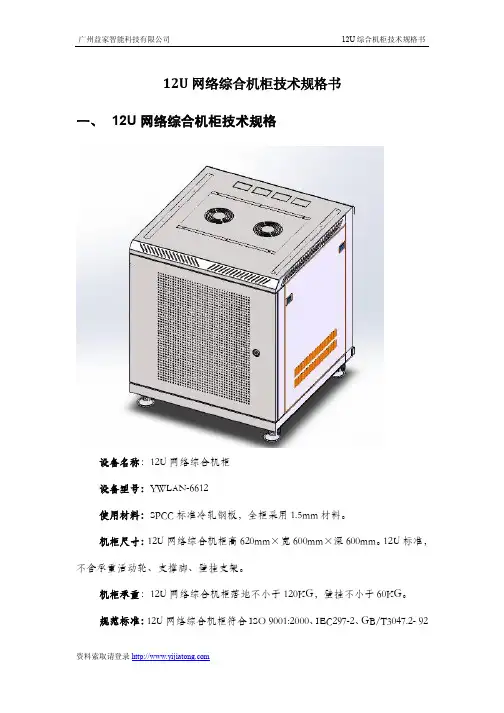
12U网络综合机柜技术规格书一、12U网络综合机柜技术规格设备名称:12U网络综合机柜设备型号:YWLAN-6612使用材料:SPCC标准冷轧钢板,全柜采用1.5mm材料。
机柜尺寸:12U网络综合机柜高620mm×宽600mm×深600mm。
12U标准,不含承重活动轮、支撑脚、壁挂支架。
机柜承重:12U网络综合机柜落地不小于120KG,壁挂不小于60KG。
规范标准:12U网络综合机柜符合ISO 9001:2000、IEC297-2、GB/T3047.2- 92标准;兼容ETSI 标准。
表面工艺:脱脂、酸洗磷化、静电喷塑、按国标IP23级静电喷涂处理。
散热设计:12U 网络综合机柜风扇组件位于机柜顶上外部,机柜顶部设轴流风扇(220V )两只,并装有引入线插头;以便于散热、更换及走线;通风设计:12U 网络综合机柜机柜前门为单开网孔门,开均匀网孔,通风率达到70%以上,机柜操作便利性设计(1)配置侧板、前柜门、插座。
(2)前门开启角度≥180度,侧板采用快开式侧门结构方式,可方便拆卸;机柜侧面带散热孔;单开网孔门,通风率75%机顶内置风扇盘。
安装2个轴流风扇风扇(3)机柜左右上下对称结构,上下后部有多个敲落孔,方便客户上走线,下走线和背部走线。
(4)壁挂、落地两种安装方式,底部设计四个承重活动轮及承重支撑脚,便于灵运移动及承重。
接地保护装置配置接地装置,符合ROHS 标准,接地排采用H62黄铜五孔地排,3mm*30mm*152mm ,安装尺寸136mm ,中间螺丝M8*12,两端螺丝M10*18,安装孔位8*10mm ,螺丝表面镀彩锌,铜件表面镀镍,配带接线鼻,带保护套;19寸安装6位国标PDU 排插黑色6位国标电源排插,10A 输入,10A 国标输出,带过载保护及带灯总开关,电源线3*0.75*1.8M,安装耳与上面板为一体,19"正方向安装,机柜标配电源排插,19”标准安装条机柜前后均设19”标准条,距门内侧100mm ,机柜立柱可根据设备安装需求进行前后调整。

SUN ELECTRICINSTALLATION OVERVIEW:_____________________________________________The Installation Procedures listed are for the SUN KOOL KARE. The unit is shipped as a fully assembled unit, with the exception of the items listed in the Parts & Accessories List per tester.PLEASE READ THESE INSTRUCTIONS COMPLETELY BEFORE SETTING UP UNITModel:SUN KOOL KARE EEAC101BR-12 UNIT SETUP Page:1 of 5Installation InstructionsINSTALLATION MUST BE PERFORMEDBYQUALIFIED SUN PERSONNEL ONLY!THIS UNIT MUST BE PLUGGED INTO A PROPER AC OUTLET FOR UNIT TO OPERATE CORRECTLY. REFER TO THE UNIT ID PLATE LOCATED ON BACK OF UNIT. EXTENSION CORDS ARE NOT RECOMMENDED,BUT IF AN EXTENSION CORD MUST BE USED, USE A CORD THAT IS LESS THAN 50 FEET WITH A 16 AWG, OR ABOVE 50 FEET AND LESS THAN 100 FEET WITH A 14 AWG.!USE STANDARD REFRIGERANT HANDLINGSAFETY PROCEDURES WHEN PERFORMING INSTALLATION ALWAYS WEAR SAFETY GOGGLES, DON’T SPILL OR TOUCH LIQUID REFRIGERANT, AVOID FLAMES, AND EXCESSIVE HEAT. USE ONLY IN WELL VENTILATED AREA.PARTS & ACCESSORIES LIST FOR EEAC101B:_____________________________PART NUMBER DESCRIPTION QTY 0119038601Literature Kit 10647019601Adapter, GM10647019701Adapter, Quick-Disconnect, GM/Ford 10647019901Adapter, Quick-Disconnect, Large GM 10647020001Adapter, Ford10692183401Questionnaire, SEL 1403C 10692239801Installation instructions 10692239301Video Tape 14211000101Envelope17009244703Recovery Tank Assembly 1EAH0013C00AGauge Set, Uniweld1REQUIRED TOOLS:____________________________________________________• Screwdriver (Flat Blade and Phillips)• Safety Goggles (0001-5005)•Refrigerant Oil (Mineral) or Superlube (0681-0193-02 or -03)UNPACKING UNIT AND ACCESSORIES:___________________________________1. Cut Straps (A), and slide the carton (B) off the pallet (C).2. Remove the top of the carton (D), and packing foam (E)from unit. Split the corners of the base carton (F).3. Remove all boxes (G) and packing material (H) fromscale/tank compartment.4. Lean the unit (I) so it can be rolled off the base carton (F).5. Lean one side of unit (I) so packing foam (J) can beremoved. Repeat for other side.6. Inventory all items using the Parts & Accessories list andinspect for damage.ACBDEF HGIJ FIGURE 1 UNIT PACKAGEPARTS & ACCESSORIES SETUP:_________________________________________1. Remove the Gauge Set Assembly (EAH0013C00A) from the gauge set box and place on gaugeset bracket.2. Remove the Blue and Red Hoses from the gauge set box and OIL the seals on each end.3. Connect the open end of the Blue and Red Hoses to the Gauge Set respectively.4. For the EEAC101A, place the four adapters in the Storage Compartment.5. Remove the User's Manual from the Literature Kit, and place the remainder of the Literature Kit(0119038601) in the Storage Compartment.BE SURE TO REVIEW THE USER'S MANUAL WITH THE CUSTOMER DURING TRAINING.Then before installing the User's Manual Envelope, ask where the customer would like the envelope installed. There is also a Video Tape (0692239301) supplied and can be viewed at the customer's convenience.6. Peel the backing from the User's Manual Envelope (4211000101) and apply the envelope, withthe open end on top, to either side of the unit, or in the location designated by the customer.7. Place the User's Manual in the Envelope.8. Remove Recovery Tank (7009244703) from its box. Remove cardboard wrap from RecoveryTank. Set on floor in front of unit.PREPARING NEW RECOVERY TANK:_____________________________________1. Referring to FIGURE 2, open the BLUE valve onRecovery Tank to release ALL COMPRESSED AIR.2. Remove the Particle Filter from the Recovery Tank.OIL seal, and re-attach to Recovery Tank. (BLUESIDE)3. Remove the Yellow Hose from the gauge set box. OILthe seals on each end of hose.4. Attach open end of Yellow Hose to BLUE valve ofRecovery Tank. Attach other end of Yellow Hose toservice port on front of unit. Open ball valve on yellowhose.5. Plug AC Cord to a 115VAC outlet. Turn unit on usingthe front power switch.FIGURE 2 RECOVERY TANK!THIS UNIT MUST BE PLUGGED IN TO A PROPER AC OUTLET FOR UNITTO OPERATE CORRECTLY. REFER TO UNIT ID PLATE LOCATED ONBACK OF UNIT. EXTENSION CORDS ARE NOT RECOMMENDED, BUTIF AN EXTENSION CORD MUST BE USED, USE A CORD THAT IS LESSTHAN 50 FEET WITH A 16 AWG, OR ABOVE 50 FEET AND LESS THAN100 FEET WITH A 14 AWG.PREPARING NEW RECOVERY TANK continued:6. Following the displays in FIGURE 3, to program a 10 minute vacuum time.7. Once completed, close Recovery Tank valve (BLUE) and remove Yellow Hose from RecoveryTank.8. Re-OIL seal on Yellow Hose and connect to center port on Gauge Set.9. Place Recovery Tank on scale. Tank fittings should face straight out the back of unit. Connectvelcro strap and tighten belt.10. Remove bubble wrap from Red and Blue Hoses on unit11. OIL seals on the anti-blow back valves on Red and Blue Hoses from unit. Connect respectively toRecovery Tank. Refer to FIGURE 4YESS T AR T I N G S C R E E NWill you Recycle from Vehicle this sequence?YESWill you be charging sequence?Will you be pulling a Vacuum this this sequence?Enter time to pull Vacuum on vehicle:Enter time to hold 10 minutes U PVacuum:00 minutes D O W NE N T E RN OYES N OYESN OU P D O W NE N T E R FIGURE 3 VACUUM MODEFIGURE 4 INSTALLING TANKCHARGING RECOVERY TANK:___________________________________________NOTE:THIS PROCEDURE IS USED TO SETUP THE UNIT FOR CHARGING. RECOVERY TANKSHOULD HAVE AT LEAST A 25” VACUUM. THIS PROCEDURE IS DONE WHEN RECOVERY TANK IS ON THE SCALE1. Be sure Recovery Tank valves (B) are closed. Referto FIGURE 52. Disconnect the Red and Blue hoses from theRecovery Tank.3. Disconnect and Re-Oil both the seals on Yellow hose(C). Connect the long side of the Yellow Hose to the Virgin Tank.4. Connect the short side of the Yellow Hose to the RedValve on the Recovery Tank (B).5. Open the Red Valve on the Recovery Tank.6. Invert the Virgin Tank (A) and open valve. OpenHand Valve (D) on the Yellow Hose to allow the refrigerant to flow.7. Raise the Virgin Tank to a higher level than theRecovery Tank. Gravity and vacuum will transfer the liquid refrigerant to the Recovery Tank faster than reclaiming it.8. Press <AMOUNT> to display the amount ofrefrigerant that has been transferred.9. After the desired amount of refrigerant has beentransferred, close valves on Virgin Tank andRecovery Tank. Set Virgin Tank on ground upright.10. Close Hand Valve on Yellow Hose. DisconnectYellow Hose from Recovery Tank.11. Re-Oil seals on anti-blow back valves on Red andBlue Hoses from unit and connect to Recovery Tank. Open Recovery Tank valves.12. Re-Oil seal on Yellow Hose and connect to service port on front of unit. Open Hand Valve onYellow Hose.1. Following the displays in FIGURE 6, perform arecover mode. This will reclaim the refrigerant from the hose. (Optional: Opening Virgin Tank valve will reclaim rest of refrigerant.)2. Once complete, disconnect Yellow Hose from VirginTank.1. Re-Oil seals on Yellow Hose and connect to centerport on Gauge Set.INSTALLATION COMPLETE/SETUP COMPLETEABCD FIGURE 5 CHARGING TANKSTARTING S C R E E NWill you Recycle from Vehicle this sequence?YESWill you be charging sequence?Will you be pulling a Vacuum this this sequence?NOYESNOYESNOFIGURE 6 RECOVER MODEREMEMBER TO OIL O-RINGS AND SEALS WHEN ATTACHING HOSES OR FITTINGS。
注意:不正确的操作可能会损坏外壳。
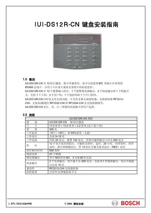
将底盖固定在适当的墙面或电气开关盒上;英寸电气开关盒安装时,请选择用螺钉在底板中‘墙面或其他尺寸电气盒安装时,请根据具体位置及尺寸选择用螺钉在底板中‘’处将其固定;如果需要使用防拆功能,IUI-DS12R-CN 必须是平面安装,将底盖上防拆开关位置上的塑料片去掉,在该位置上的墙面或盒面固定一个较长的坚硬物(如螺钉),用其顶住电路板上的防拆开关即可。
进线口AA接线端子排1接线端子排3IUI-DS12R-CN 主机PCB 板共有32个接线端子,分为(从右到左从1开始编号列表): 第一组 接线端子位置1第三组 接线端子位置1防拆开关第一组接线端子:接线端# 描述1 电源+(12伏直流)2 电源-(地)3 RS485 A接线端4 RS485 B接线端5 钥匙开关输入端6 固态继电器输出17 继电器公共端8 固态继电器输出2第二组接线端子:接线端# 描述1 防区12 公共端(地)3 防区24 防区35 公共端(地)6 防区47 防区58 公共端(地)9 防区610 防区711 公共端(地)12 防区8第三组接线端子:接线端# 描述1 防区92 公共端(地)3 防区104 防区115 公共端(地)6 防区127 即时防区8 警报输出常开端9 警报输出公共端10 警报输出常闭端11 无线设备数据线接口112 无线设备数据线接口24 P/N: F01U028699B © 2006 博世安保 IUI-DS12R-CN安装指南DS12R-CN:对于不同的地址应对应设置表中不同的值,若输入错误的值(数值长度不正确)。
可键取消刚输入的,然后重新输入。
返回到步骤4进行重新输入即可,但是若所输入的值不正确,数字长度正确,将发短3声进行提示,则必须重新输入编程地址及相应的值。
若想编程其它地址,则可重复步骤3和4。
10 P/N: F01U028699B © 2006 博世安保 IUI-DS12R-CN 安装指南5.1 编程数据查询在编程模式状态下,可以查询各个编程地址的当前值,其方法如下: 步骤 操 作 提 示1输入主码[x][x][x][x] 只有主码才具有编程模式,其它三个用户码不能用于编程。
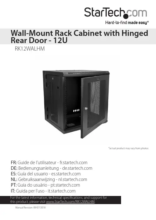
FR: Guide de l’utilisateur - DE: Bedienungsanleitung - ES: Guía del usuario - NL: Gebruiksaanwijzing - PT: Guia do usuário - IT: Guida per l’uso - RK12WALHMWall-Mount Rack Cabinet with Hinged Rear Door - 12U *actual product may vary from photosUse of Trademarks, Registered Trademarks, and other Protected Names and Symbols This manual may make reference to trademarks, registered trademarks, and otherprotected names and/or symbols of third-party companies not related in any way to . Where they occur these references are for illustrative purposes only and do not represent an endorsement of a product or service by , or an endorsement of the product(s) to which this manual applies by the third-party company in question. Regardless of any direct acknowledgement elsewhere in the body of this document, hereby acknowledges that all trademarks, registered trademarks, service marks, and other protected names and/or symbols contained in this manual and related documents are the property of their respective holders.PHILLIPS® is a registered trademark of Phillips Screw Company in the United States or other countries.Warning statements Varningsmeddelanden Waarschuwingen 注意Dichiarazioni di avvertenza AvertissementsMensagens de aviso Advertencias de uso WarnhinweiseTable of ContentsIntroduction (1)Product diagram (1)Product dimensions (2)Package contents (3)Requirements (3)Ground the enclosure (4)Lock or unlock the front or rear door (5)Remove the side panels (5)Access your cables (7)Reverse the front door (8)Adjust the depth of the mounting rails (10)Use the mounting rail tapped holes (11)Mount the enclosure to the wall (12)Install equipment (13)Technical support (14)Warranty information (14)Introduction Product diagram 13245457Front doorRear doorHorizontal mounting railVertical mounting railCable access coverCable access opening Side panel6Vent 37886Product dimensionsPackage contents• 1 x wall-mount enclosure• 1 x 1U shelf (CABSHELFV1U)• 1 x roll of hook-and-loop fastener• 48 x 12-24 cage nuts• 48 x 12-24 screws• 2 x door keys• 2 x side panel keys• 1 x instruction manualRequirements• Phillips type screwdriver• Appropriate tools and mounting hardware for the type of wall you’re using Requirements are subject to change. For the latest requirements, please visit /RK12WALHM.Ground the enclosureWarning! This product must be grounded. Do not use this product without an earth ground connection.1. Use an M6 screw to attach a grounding wire to the front or rear grounding point on the enclosure.2. Route the wire under the frame of the enclosure and connect the wire to your facility’s earth ground connection. (figure 1)figure 1Grounding wireLock or unlock the front or rear doorFor additional security, the front and rear door of the enclosure can be locked with the provided door keys.• To lock or unlock the front or rear door of the enclosure, insert one of the provided door keys in the lock on the door and turn the key clockwise or counterclockwise.Remove the side panels1. If the side panels are locked, use the provided side panel keys to unlock the panels.2. Pull the two tabs on the side panel towards the center of the panel. (figure 2)figure 2figure 33. Lift the side panel free from the enclosure. (figure 3)4.Repeat steps 1 to 3 to remove the other side panel.To put the side panels back on the enclosure, place one of the side panels in the groove at the bottom of the enclosure. Pull the two tabs on the side panel towards the center of the panel, push the top part of the side panel into the enclosure, and release the tabs. Use one of the provided side panel keys to lock the side panel.figure 4Access your cablesThere are two cable access covers on the enclosure that you can remove to access and manage your cables.1. To take off a cable access cover, use a Phillips type screwdriver to remove the two screws on both ends of the cable access cover.2. Pull the cable access cover away from the enclosure. (figure 4)To put the cable access cover back on, place the cover over the cable access opening and use a Phillips type screwdriver to insert the screws through the cover and into the enclosure. Tighten the screws.Reverse the front doorTo accommodate different rack configurations, you can reverse the front door of the enclosure so that it opens to the left or right of the enclosure. The front door of the enclosure is attached to the enclosure with levers that are located at the top and bottom of the front door.1. In the top corner of the inside of the front door, pull the lever down and move the top corner of the front door away from the enclosure.2. In the bottom corner of the inside of the front door, pull the lever up and remove the front door from the enclosure. (figure 5)figure 53. Flip the front door so that the levers are located on the opposite side.4. Position the front door so that the top and bottom levers are aligned with the washers located in the hinge area of the enclosure.5. In the top corner of the front door, pull the lever down and release it into the washer and hole in the enclosure.6. In the bottom corner of the front door, pull the lever up and release it into the washer and hole in the enclosure. (figure 6)figure 6Adjust the depth of the mounting rails The mounting rails come pre installed in the enclosure. The mounting rails can be adjusted independently in 3/4 inch (20 mm) increments to accommodate different sizes of equipment.Warning! Do not attempt to adjust the mounting rails when equipment is installed in the enclosure. Remove the equipment first before you adjust the mounting rails.1. Each of the mounting rails is connected to the enclosure with a screw and cage nut in the upper and lower corners of the mounting rail. Use a Phillips type screwdriver to remove the screws and cage nuts from the mounting rails.2. Install the cage nuts at the desired depth.3. Slide the mounting rail to the depth of the cage nuts and use a Phillips type screwdriver to install and tighten the screws that you removed in step 1. (figure 7)figure 7Use the mounting rail tapped holesThe mounting rails come preinstalled in the enclosure but you can adjust the mounting rails so that you can use the tapped holes to install your equipment.Warning! Do not attempt to adjust the mounting rails when equipment is installed in the enclosure. Remove the equipment first before you adjust the mounting rails.1. Each of the mounting rails is connected to the enclosure with a screw and cage nut in the upper and lower corners of the mounting rail. Use a Phillips type screwdriver to remove the screws and cage nuts from the mounting rails.2. Change the location of the mounting rails so that the sides of the rails with the tapped holes are facing the front door. (figure 8)3. To reattach the mounting rails to the enclosure, use a Phillips type screwdriver to install and tighten the screws that you removed in step 1.figure 8Mount the enclosure to the wallWarning! Remove all equipment from the enclosure before you attempt to mount the enclosure to the wall.Warning! Wall structures vary and it is important to make sure that the type ofwall structure and mounting hardware that you are using will properly support the mounted equipment. Failure to do so might result in personal injury and/or equipment damage. The wall structure should be capable of supporting at least four times the weight of the mounted equipment.The RK12WALHM weighs 59.5 lb. (27 kg) and can hold up to 198 lb. (90 kg) in weight.Warning! If you lack the necessary expertise to attach this product to the wall that you’re using, contact a construction professional to install the enclosure or to provide specific mounting instructions for your wall structure.The number of mounting holes on the rear door of the enclosure will vary depending on the model of your enclosure. Each mounting hole can accommodate an M8, M10, 5/16”, or 3/8” bolt.• Follow the appropriate steps for the type of wall that you’re attaching the enclosure to and attach the enclosure to the wall.Caution! The enclosure is extremely heavy and you should not attempt to lift and hang the enclosure without the assistance of other people.Install equipmentWarning! Do not add equipment to the enclosure until the enclosure is securely attached to the wall.Warning! When you load equipment into this enclosure, load the heaviest equipment in the bottom section of this enclosure first. Continue loading equipment in a descending order of weight, so that the lighter equipment is installed in the upper sections of this enclosure and the heavier items are on the bottom.This enclosure comes with cage nuts and screws but the equipment you’re installing may come with mounting hardware. Consult the documentation that came with the equipment to determine the best mounting hardware that you should use and how you should install it.1. Decide where in the enclosure you want to install the equipment and insert the cage nuts in the mounting rails.2. Line up the mounting holes on the equipment with the cage nuts.3. Insert the screws through the mounting holes on the equipment and into the cage nuts.Technical support’s lifetime technical support is an integral part of our commitment to provide industry-leading solutions. If you ever need help with your product, visit /support and access our comprehensive selection of online tools, documentation, and downloads.For the latest drivers/software, please visit /downloads Warranty informationThis product is backed by a five-year warranty. warrants its products against defects in materials and workmanship for the periods noted, following the initial date of purchase. During this period, the products may be returned for repair, or replacement with equivalent products at our discretion. The warranty covers parts and labor costs only. does not warrant its products from defects or damages arising from misuse, abuse, alteration, or normal wear and tear.Limitation of liabilityIn no event shall the liability of Ltd. and USA LLP (or their officers, directors, employees or agents) for any damages (whether direct or indirect, special, punitive, incidental, consequential, or otherwise), loss of profits, loss of business, or any pecuniary loss, arising out of or related to the use of the product exceed the actual price paid for the product. Some states do not allow the exclusion or limitation of incidental or consequential damages. If such laws apply, the limitations or exclusions contained in this statement may not apply to you.Hard-to-find made easy. At , that isn’t a slogan. It’s a promise. is your one-stop source for every connectivity part you need. From the latest technology to legacy products — and all the parts that bridge the old and new — we can help you find the parts that connect your solutions.We make it easy to locate the parts, and we quickly deliver them wherever they need to go. Just talk to one of our tech advisors or visit our website. You’ll be connected to the products you need in no time.Visit for complete information on all products and to access exclusive resources and time-saving tools. is an ISO 9001 Registered manufacturer of connectivity and technology parts. was founded in 1985 and has operations in the United States,。
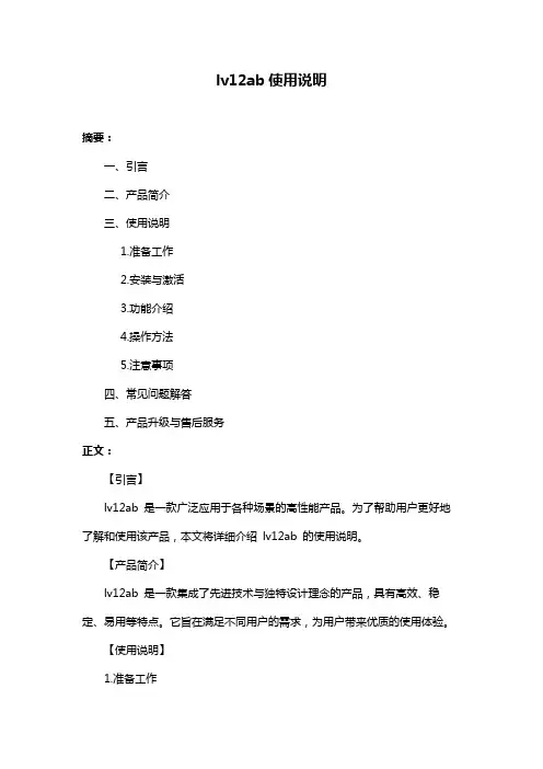
lv12ab使用说明摘要:一、引言二、产品简介三、使用说明1.准备工作2.安装与激活3.功能介绍4.操作方法5.注意事项四、常见问题解答五、产品升级与售后服务正文:【引言】lv12ab 是一款广泛应用于各种场景的高性能产品。
为了帮助用户更好地了解和使用该产品,本文将详细介绍lv12ab 的使用说明。
【产品简介】lv12ab 是一款集成了先进技术与独特设计理念的产品,具有高效、稳定、易用等特点。
它旨在满足不同用户的需求,为用户带来优质的使用体验。
【使用说明】1.准备工作在使用lv12ab 前,请确保您的设备满足产品要求的硬件和软件配置,以便获得最佳性能。
同时,请确保设备已连接到电源,并确保电源稳定。
2.安装与激活请按照产品附带的安装指南进行安装。
安装完成后,请按照提示进行激活。
激活过程中,请确保您的设备已连接到网络,以便顺利完成激活。
3.功能介绍lv12ab 具有以下主要功能:(1)功能一(2)功能二(3)功能三4.操作方法(1)操作一:具体操作步骤(2)操作二:具体操作步骤(3)操作三:具体操作步骤5.注意事项在使用lv12ab 过程中,请务必注意以下事项:(1)请勿在潮湿、高温或灰尘环境中使用产品,以免影响设备性能和寿命。
(2)请勿擅自拆卸、改装或维修产品,以免造成安全事故。
(3)请定期检查设备运行状况,如有异常,请及时联系售后服务。
【常见问题解答】1.问题一:如何解决?2.问题二:如何解决?3.问题三:如何解决?【产品升级与售后服务】lv12ab 产品的升级和售后服务政策如下:1.产品升级:根据用户需求和产品实际情况,我们将不定期推出升级版本。
用户可以通过官方网站或指定渠道获取升级信息,并根据提示进行升级。
2.售后服务:我们提供一年的免费质保服务。
在质保期内,如产品出现非人为损坏的质量问题,我们将免费提供维修或更换。


DU-05349-001_v9.0 | September 2017Installation and Verification on WindowsTABLE OF CONTENTS Chapter 1. Introduction (1)1.1. System Requirements (1)1.1.1. x86 32-bit Support (2)1.2. About This Document (3)Chapter 2. Installing CUDA Development T ools (4)2.1. Verify You Have a CUDA-Capable GPU (4)2.2. Download the NVIDIA CUDA T oolkit (4)2.3. Install the CUDA Software (5)2.3.1. Uninstalling the CUDA Software (7)2.4. Use a Suitable Driver Model (8)2.5. Verify the Installation (8)2.5.1. Running the Compiled Examples (8)Chapter 3. Compiling CUDA Programs (11)3.1. Compiling Sample Projects (11)3.2. Sample Projects (11)3.3. Build Customizations for New Projects (12)3.4. Build Customizations for Existing Projects (12)Chapter 4. Additional Considerations (14)CUDA® is a parallel computing platform and programming model invented by NVIDIA. It enables dramatic increases in computing performance by harnessing the power of the graphics processing unit (GPU).CUDA was developed with several design goals in mind:‣Provide a small set of extensions to standard programming languages, like C, that enable a straightforward implementation of parallel algorithms. With CUDA C/C++, programmers can focus on the task of parallelization of the algorithms rather than spending time on their implementation.‣Support heterogeneous computation where applications use both the CPU and GPU. Serial portions of applications are run on the CPU, and parallel portions are offloaded to the GPU. As such, CUDA can be incrementally applied to existingapplications. The CPU and GPU are treated as separate devices that have their own memory spaces. This configuration also allows simultaneous computation on the CPU and GPU without contention for memory resources.CUDA-capable GPUs have hundreds of cores that can collectively run thousands of computing threads. These cores have shared resources including a register file and a shared memory. The on-chip shared memory allows parallel tasks running on these cores to share data without sending it over the system memory bus.This guide will show you how to install and check the correct operation of the CUDA development tools.1.1. System RequirementsTo use CUDA on your system, you will need the following installed:‣ A CUDA-capable GPU‣ A supported version of Microsoft Windows‣ A supported version of Microsoft Visual Studio‣the NVIDIA CUDA Toolkit (available at /cuda-downloads)The next two tables list the currently supported Windows operating systems and compilers.T able 1 Windows Operating System Support in CUDA 9.0T able 2 Windows Compiler Support in CUDA 9.0x86_32 support is limited. See the x86 32-bit Support section for details.1.1.1. x86 32-bit SupportNative development using the CUDA Toolkit on x86_32 is unsupported. Deployment and execution of CUDA applications on x86_32 is still supported, but is limited to use with GeForce GPUs. To create 32-bit CUDA applications, use the cross-development capabilities of the CUDA Toolkit on x86_64.Support for developing and running x86 32-bit applications on x86_64 Windows is limited to use with:‣GeForce GPUs‣CUDA Driver‣CUDA Runtime (cudart)‣CUDA Math Library (math.h)‣CUDA C++ Compiler (nvcc)‣CUDA Development Tools1.2. About This DocumentThis document is intended for readers familiar with Microsoft Windows operating systems and the Microsoft Visual Studio environment. You do not need previous experience with CUDA or experience with parallel computation.Basic instructions can be found in the Quick Start Guide. Read on for more detailed instructions.The setup of CUDA development tools on a system running the appropriate version of Windows consists of a few simple steps:‣Verify the system has a CUDA-capable GPU.‣Download the NVIDIA CUDA Toolkit.‣Install the NVIDIA CUDA Toolkit.‣Test that the installed software runs correctly and communicates with the hardware.2.1. Verify You Have a CUDA-Capable GPUYou can verify that you have a CUDA-capable GPU through the Display Adapters section in the Windows Device Manager. Here you will find the vendor name and model of your graphics card(s). If you have an NVIDIA card that is listed in http:// /cuda-gpus, that GPU is CUDA-capable. The Release Notes for the CUDA Toolkit also contain a list of supported products.The Windows Device Manager can be opened via the following steps:1.Open a run window from the Start Menu2.Run:control /name Microsoft.DeviceManager2.2. Download the NVIDIA CUDA T oolkitThe NVIDIA CUDA Toolkit is available at /cuda-downloads. Choose the platform you are using and one of the following installer formats:work Installer: A minimal installer which later downloads packages required forinstallation. Only the packages selected during the selection phase of the installerare downloaded. This installer is useful for users who want to minimize download time.2.Full Installer: An installer which contains all the components of the CUDA Toolkitand does not require any further download. This installer is useful for systemswhich lack network access and for enterprise deployment.The CUDA Toolkit installs the CUDA driver and tools needed to create, build and run a CUDA application as well as libraries, header files, CUDA samples source code, and other resources.Download VerificationThe download can be verified by comparing the MD5 checksum posted at http:// /cuda-downloads/checksums with that of the downloadedfile. If either of the checksums differ, the downloaded file is corrupt and needs to be downloaded again.To calculate the MD5 checksum of the downloaded file, follow the instructions at http:// /kb/889768.2.3. Install the CUDA SoftwareBefore installing the toolkit, you should read the Release Notes, as they provide details on installation and software functionality.The driver and toolkit must be installed for CUDA to function. If you have notinstalled a stand-alone driver, install the driver from the NVIDIA CUDA T oolkit.The installation may fail if Windows Update starts after the installation has begun.Wait until Windows Update is complete and then try the installation again. Graphical InstallationInstall the CUDA Software by executing the CUDA installer and following the on-screen prompts.Silent InstallationThe installer can be executed in silent mode by executing the package with the -s flag. Additional parameters can be passed which will install specific subpackages instead of all packages. See the table below for a list of all the subpackage names.T able 3 Possible Subpackage NamesFor example, to install only the compiler and driver components:<PackageName>.exe -s compiler_9.0 Display.DriverExtracting and Inspecting the Files ManuallySometimes it may be desirable to extract or inspect the installable files directly, such as in enterprise deployment, or to browse the files before installation. The full installation package can be extracted using a decompression tool which supports the LZMA compression method, such as 7-zip or WinZip.Once extracted, the CUDA Toolkit files will be in the CUDAToolkit folder, and similarily for the CUDA Samples and CUDA Visual Studio Integration. Within each directory isa .dll and .nvi file that can be ignored as they are not part of the installable files.Accessing the files in this manner does not set up any environment settings, suchas variables or Visual Studio integration. This is intended for enterprise-leveldeployment.2.3.1. Uninstalling the CUDA SoftwareAll subpackages can be uninstalled through the Windows Control Panel by using the Programs and Features widget.2.4. Use a Suitable Driver ModelOn Windows 7 and later, the operating system provides two driver models under which the NVIDIA Driver may operate:‣The WDDM driver model is used for display devices.‣The Tesla Compute Cluster (TCC) mode of the NVIDIA Driver is available for non-display devices such as NVIDIA Tesla GPUs, and the GeForce GTX Titan GPUs; it uses the Windows WDM driver model.The TCC driver mode provides a number of advantages for CUDA applications on GPUs that support this mode. For example:‣TCC eliminates the timeouts that can occur when running under WDDM due to the Windows Timeout Detection and Recovery mechanism for display devices.‣TCC allows the use of CUDA with Windows Remote Desktop, which is not possible for WDDM devices.‣TCC allows the use of CUDA from within processes running as Windows services, which is not possible for WDDM devices.‣TCC reduces the latency of CUDA kernel launches.TCC is enabled by default on most recent NVIDIA Tesla GPUs. To check which driver mode is in use and/or to switch driver modes, use the nvidia-smi tool that is included with the NVIDIA Driver installation (see nvidia-smi -h for details).Keep in mind that when TCC mode is enabled for a particular GPU, that GPU cannotbe used as a display device.NVIDIA GeForce GPUs (excluding GeForce GTX Titan GPUs) do not support TCC mode.2.5. Verify the InstallationBefore continuing, it is important to verify that the CUDA toolkit can find and communicate correctly with the CUDA-capable hardware. To do this, you need to compile and run some of the included sample programs.2.5.1. Running the Compiled ExamplesThe version of the CUDA Toolkit can be checked by running nvcc -V in a Command Prompt window. You can display a Command Prompt window by going to:Start > All Programs > Accessories > Command PromptCUDA Samples include sample programs in both source and compiled form. To verify a correct configuration of the hardware and software, it is highly recommended that you run the deviceQuery program located atC:\ProgramData\NVIDIA Corporation\CUDA Samples\v9.0\bin\win64\ReleaseThis assumes that you used the default installation directory structure. If CUDA is installed and configured correctly, the output should look similar to Figure 1.Figure 1 Valid Results from deviceQuery CUDA SampleThe exact appearance and the output lines might be different on your system. The important outcomes are that a device was found, that the device(s) match what is installed in your system, and that the test passed.If a CUDA-capable device and the CUDA Driver are installed but deviceQuery reports that no CUDA-capable devices are present, ensure the deivce and driver are properly installed.Running the bandwidthTest program, located in the same directory as deviceQuery above, ensures that the system and the CUDA-capable device are able to communicate correctly. The output should resemble Figure 2.Figure 2 Valid Results from bandwidthT est CUDA SampleThe device name (second line) and the bandwidth numbers vary from system to system. The important items are the second line, which confirms a CUDA device was found, and the second-to-last line, which confirms that all necessary tests passed.If the tests do not pass, make sure you do have a CUDA-capable NVIDIA GPU on your system and make sure it is properly installed.To see a graphical representation of what CUDA can do, run the sample Particles executable atC:\ProgramData\NVIDIA Corporation\CUDA Samples\v9.0\bin\win64\ReleaseThe project files in the CUDA Samples have been designed to provide simple, one-click builds of the programs that include all source code. To build the Windows projects (for release or debug mode), use the provided *.sln solution files for Microsoft Visual Studio 2010, 2012, or 2013. You can use either the solution files located in each of the examples directories inC:\ProgramData\NVIDIA Corporation\CUDA Samples\v9.0\<category>\<sample_name>or the global solution files Samples*.sln located inC:\ProgramData\NVIDIA Corporation\CUDA Samples\v9.0CUDA Samples are organized according to <category>. Each sample is organized into one of the following folders: (0_Simple, 1_Utilities, 2_Graphics, 3_Imaging, 4_Finance, 5_Simulations, 6_Advanced, 7_CUDALibraries).3.1. Compiling Sample ProjectsThe bandwidthTest project is a good sample project to build and run. It is located in the NVIDIA Corporation\CUDA Samples\v9.0\1_Utilities\bandwidthTest directory.If you elected to use the default installation location, the output is placed in CUDA Samples\v9.0\bin\win64\Release. Build the program using the appropriate solution file and run the executable. If all works correctly, the output should be similar to Figure 2.3.2. Sample ProjectsThe sample projects come in two configurations: debug and release (where release contains no debugging information) and different Visual Studio projects.A few of the example projects require some additional setup. The simpleD3D9 example requires the system to have a Direct3D SDK (June 2010 or later) installed and the Visual C++ directory paths (located in Tools > Options...) properly configured. Consult the Direct3D documentation for additional details.These sample projects also make use of the $CUDA_PATH environment variable to locate where the CUDA Toolkit and the associated .props files are.The environment variable is set automatically using the Build Customization CUDA 9.0.props file, and is installed automatically as part of the CUDA Toolkit installation process.T able 4 CUDA Visual Studio .props locationsYou can reference this CUDA 9.0.props file when building your own CUDA applications.3.3. Build Customizations for New ProjectsWhen creating a new CUDA application, the Visual Studio project file must be configured to include CUDA build customizations. To accomplish this, click File-> New | Project... NVIDIA-> CUDA->, then select a template for your CUDA Toolkit version. For example, selecting the "CUDA 9.0 Runtime" template will configure your project for use with the CUDA 9.0 Toolkit. The new project is technically a C++ project (.vcxproj) that is preconfigured to use NVIDIA's Build Customizations. All standard capabilities of Visual Studio C++ projects will be available.To specify a custom CUDA Toolkit location, under CUDA C/C++, select Common, and set the CUDA Toolkit Custom Dir field as desired. Note that the selected toolkit must match the version of the Build Customizations.3.4. Build Customizations for Existing ProjectsWhen adding CUDA acceleration to existing applications, the relevant Visual Studio project files must be updated to include CUDA build customizations. This can be done using one of the following two methods:1.Open the Visual Studio project, right click on the project name, and select BuildCustomizations..., then select the CUDA Toolkit version you would like to target.2.Alternatively, you can configure your project always to build with the most recentlyinstalled version of the CUDA Toolkit. First add a CUDA build customization to your project as above. Then, right click on the project name and select Properties.Under CUDA C/C++, select Common, and set the CUDA Toolkit Custom Dir fieldto $(CUDA_PATH) . Note that the $(CUDA_PATH) environment variable is set by the installer.While Option 2 will allow your project to automatically use any new CUDA Toolkit version you may install in the future, selecting the toolkit version explicitly as in Option 1 is often better in practice, because if there are new CUDA configuration options added to the build customization rules accompanying the newer toolkit, you would not see those new options using Option 2.If you use the $(CUDA_PATH) environment variable to target a version of the CUDA Toolkit for building, and you perform an installation or uninstallation of any version of the CUDA Toolkit, you should validate that the $(CUDA_PATH) environment variable points to the correct installation directory of the CUDA Toolkit for your purposes. You can access the value of the $(CUDA_PATH) environment variable via the following steps:1.Open a run window from the Start Menu2.Run:control sysdm.cpl3.Select the "Advanced" tab at the top of the window4.Click "Environment Variables" at the bottom of the windowFiles which contain CUDA code must be marked as a CUDA C/C++ file. This can done when adding the file by right clicking the project you wish to add the file to, selecting Add\New Item, selecting NVIDIA CUDA 9.0\Code\CUDA C/C++ File, and then selecting the file you wish to add.Note for advanced users: If you wish to try building your project against a newer CUDA Toolkit without making changes to any of your project files, go to the Visual Studio command prompt, change the current directory to the location of your project, and execute a command such as the following:msbuild <projectname.extension> /t:Rebuild /p:CudaToolkitDir="drive:/path/to/ new/toolkit/"Now that you have CUDA-capable hardware and the NVIDIA CUDA Toolkit installed, you can examine and enjoy the numerous included programs. To begin using CUDA to accelerate the performance of your own applications, consult the CUDA C Programming Guide, located in the CUDA Toolkit documentation directory.A number of helpful development tools are included in the CUDA Toolkit or are available for download from the NVIDIA Developer Zone to assist you as you develop your CUDA programs, such as NVIDIA® Nsight™ Visual Studio Edition, NVIDIA Visual Profiler, and cuda-memcheck.For technical support on programming questions, consult and participate in the developer forums at /cuda/.NoticeALL NVIDIA DESIGN SPECIFICATIONS, REFERENCE BOARDS, FILES, DRAWINGS, DIAGNOSTICS, LISTS, AND OTHER DOCUMENTS (TOGETHER AND SEPARATEL Y, "MATERIALS") ARE BEING PROVIDED "AS IS." NVIDIA MAKES NO WARRANTIES, EXPRESSED, IMPLIED, STATUTORY, OR OTHERWISE WITH RESPECT TO THE MATERIALS, AND EXPRESSL Y DISCLAIMS ALL IMPLIED WARRANTIES OF NONINFRINGEMENT, MERCHANTABILITY, AND FITNESS FOR A PARTICULAR PURPOSE.Information furnished is believed to be accurate and reliable. However, NVIDIA Corporation assumes no responsibility for the consequences of use of such information or for any infringement of patents or other rights of third parties that may result from its use. No license is granted by implication of otherwise under any patent rights of NVIDIA Corporation. Specifications mentioned in this publication are subject to change without notice. This publication supersedes and replaces all other information previously supplied. NVIDIA Corporation products are not authorized as critical components in life support devices or systems without express written approval of NVIDIA Corporation.TrademarksNVIDIA and the NVIDIA logo are trademarks or registered trademarks of NVIDIA Corporation in the U.S. and other countries. Other company and product names may be trademarks of the respective companies with which they are associated. Copyright© 2009-2017 NVIDIA Corporation. All rights reserved.。

用VMware 9安装Ubuntu 12.04具体过程(图解)/s/blog_6fe3efa301016tca.html本机体系: WIN7虚拟机:VMware Workstation 9 (英文版)安装目标:Ubuntu Desktop 12.04 LTS 请先下载好iso镜像文件本机是64位操作系统,我下载了64位黄钻用的Ubuntu后,安装时提示装不了,说是不对应,自动提取我的系统信息不是64位的。
于是,我就下载安装了32位的,安装、设置一切很顺利,可是每次开启虚拟机时就出现问题了:Host SMBus controllor not enabled。
vmwaer虚拟机部署-ubuntu piix4_smbus: Host SMBus controller not enabled!该错误我本地安装时,主要是因为操作系统版本与CPU不匹配;例:我的CPU是64位,如果安装32位的UBUNTU,则会报“piix4_smbus: Host SMBus controller not enabled!”,但如果是安装64位的UBUNTU则一切OK;此问题还还在试验中,如若知道怎么解决,请于博主我联系,一同交流探讨,谢谢了~~!!具体过程图解:0. 初始画面,点击“Create a New Virtual Machine”(左上Ubuntu为本人已有开辟景象机,请忽视)1. 点击“Custom(自定义)”2. 无需选择,直接Next(上方是选Workstation版本的兼容性的,这里默认为当前版本8.0,之前版本的不合在于Limitations(局限),如内存更少,不支撑HD Audio等)3. 选择“I will install the operating system later”这里无严格请求的同窗,是可以选择第二项“Installer disc image file (ios)”的,之后会VMware会主动得知你的iso是Linux(Ubuntu),只请求你输入Full name,和用户名暗码等简单的用户设定,然则这是一个Easy install,如VMware原文所说“When the New Virtual Wizard detects an operating system that supports Easy Install,the wizard prompts you for information about the guest operating system. After the virtual machine is created,the guest operating system installation is automated and VMware Tools is installed.” 我感觉是因为这个OS的主动安装,不完全,导致一些核心号令无法应用、无反响等一些题目。
NSmart Loop-Powered RTD In-HeadTemperature TransmitterTX12£3350ߜUser Trim—Null Out Sensor ErrorߜUnique Push ButtonConfiguration Without PC ߜHigh StabilityߜProgrammable Burnout ߜLED Sensor Fail Indicator ߜReconfigure in SecondsThe TX12 head mountedtemperature transmitter connects to any standard Pt100 resistance sensor and converts the linearised temperature to a 4 to 20 mA signal.The transmitter is a two wire device,and is fully configurable by the user,over a wide temperature range, with the aid of a simple push button. This new TX12 design incorporates additional configuration menus,allowing the user to push button trim the transmitter output at both zero and span, ideal for trimming out sensor errors. The transmitters advanced circuitry ensures high stability over the wide operating ambient temperature ranges experienced by head mounted devices.One of the transmitters features is the program LED, which provides visual indication of sensor fault when in normal operation and is also used to guide the operator through the simple menus during configuration.SpecificationsInputSensor Type:Pt100 100R @ 0°C 2 or 3 WireSensor Range:-200 to 850°C (18 to 390°F) øSensor Connection:Screw terminal Minimum Span:25°C (77°F)Linearisation:BS EN 60751(IEC 751)standard/JISC 1604Measurement Accuracy:0.1°C ±0.05% of readingThermal Drift:25 ppm/°C Excitation Current:<200 uALead Resistance Effect:0.002°C/ Maximum Lead Resistance: 20 per legOutputOutput Type:2 wire, 4 to 20 mA current loopOutput Range:(4.0 to 20.0) mA Output Connection:Screw terminal Maximum Output:21.5 mA (in high burnout condition)Minimum Output:3.8 mA (in low burnout condition)Accuracy:(mA output /2000) or 5 uA (whichever is the greater)Loop Voltage Effect:0.2 uA/V Thermal Drift:1 uA /°C Maximum Output Load:[(Vsupply-10)/20]K (Example: 700 @ 24V)General SpecificationsUpdate Time:500 mSResponse Time:1 second Start Up Time:4 seconds (I out < 4 mA during start up)Warm-Up Time:1 minute to full accuracyPower Supply:10 to 30 VdcEnvironmentalAmbient Operating Range:-40 to 85°C (-40 to 185°F)Ambient Storage Temperature:-50 to 90°C (-58 to 194°F)Ambient Humidity Range:10 to 90% RH non condensingPhysicalDimensions:43 mm diameter; 21 mm height (1.7"; 0.8")Weight:31 g (0.068 lb) (encapsulated)ApprovalsEMC - BS EN 61326 :1998:Electrical equipment for measurement control and laboratory useANNEX A:Immunity test requirements for equipment intended for use in industrial locationsANNEX F:Test configurations,operational conditions and performance criteria for transducers with integrated or remote signal conditioningIEC 61000-4-2:Electrostatic discharge IEC 61000-4-3:EM fieldIEC 61000-4-4:Transient burst (output)IEC 61000-4-5:Surge (output)Note:Sensor input wires to be less than3 m to comply.Comes with operator’s manual.Ordering Example: TX12, RTD transmitter and PSR-24L-230-UK , regulated power supply with stripped leads, £33.50 + 40.20 = £73.70.TX12, £33.50, shown larger than actual size.CANADA www.omega.ca Laval(Quebec)1-800-TC-OMEGA UNITED KINGDOM Manchester,England0800-488-488GERMANY www.omega.deDeckenpfronn,Germany************FRANCE www.omega.fr 088-466-342BENELUX www.omega.nl 0800-099-33-44UNITED STATES 1-800-TC-OMEGA Stamford,CT.CZECH REPUBLIC www.omegaeng.cz Karviná,Czech Republic596-311-899TemperatureCalibrators, Connectors, General Test and Measurement Instruments, Handheld Instruments for Temperature Measurement, Ice Point References, Indicating Labels,Crayons, Cements and Lacquers, Infrared Temperature Measurement Instruments, Recorders, Relative Humidity Measurement Instruments, PT100 Probes, PT100 Elements,Temperature & Process Meters, Timers and Counters,Temperature and Process Controllers and Power Switching Devices, Thermistor Elements, Probes and Assemblies,Thermocouples, Thermowells and Head and WellAssemblies, Transmitters, Thermocouple Wire, RTD ProbesPressure,Strain and ForceDisplacement Transducers, Dynamic Measurement Force Sensors, Instrumentation for Pressure and StrainMeasurements, Load Cells, Pressure Gauges, PressureReference Section, Pressure Switches, Pressure Transducers,Proximity Transducers, Regulators, Pressure Transmitters,Strain Gauges, Torque Transducers, ValvespH and ConductivityConductivity Instrumentation,Dissolved OxygenInstrumentation,Environmental Instrumentation,pH Electrodes and Instruments,Water and Soil Analysis InstrumentationHeatersBand Heaters,Cartridge Heaters,Circulation Heaters,Comfort Heaters,Controllers,Meters and SwitchingDevices,Flexible Heaters,General Test and Measurement Instruments,Heater Hook-up Wire,Heating Cable Systems,Immersion Heaters,Process Air and Duct,Heaters,Radiant Heaters,Strip Heaters,Tubular HeatersFlow and LevelAir Velocity Indicators,Doppler Flowmeters,LevelMeasurement,Magnetic Flowmeters,Mass Flowmeters,Pitot Tubes,Pumps,Rotameters,Turbine and Paddle Wheel Flowmeters,Ultrasonic Flowmeters,Valves,Variable Area Flowmeters,Vortex Shedding FlowmetersData AcquisitionAuto-Dialers and Alarm Monitoring Systems,Communication Products and Converters,Data Acquisition and Analysis Software,Data LoggersPlug-in Cards,Signal Conditioners,USB,RS232,RS485and Parallel Port Data Acquisition Systems,Wireless Transmitters and Receivers。
NI Circuit Design Suite(Multisim)12.0安装与软件激活方法编写:樊伟敏 2012-2-13 NI Circuit Design Suite 12.0 又称为Multisim 12.0是美国国家仪器有限公司(NI)在2012 年1月推出的最新版本。
它以Windows为基础的仿真工具, 可实现对电路原理图的图形输入、 电路硬件描述语言输入方式、 电路分析、 电路仿真、 仿真仪器测试、 射频分析、 单片机分析、 PCB 布局布线等。
NI 电路设计套件包括:NI Multisim、NI Ultiboard 和NI Multisim MCU Module。
最新版Multisim 软件在功能上进行了提升,用于仿真的器件增加到21862个, 仪器与分析记录仪可设置默认背景色等功能。
安装NI公司提供的Chinese中文包以后,界面菜单可显示为简体中文。
1. Multisim不同版本的软件对操作系统的要求如表1所示。
表 1Multisim 不同版本的软件对操作系统的要求表操作系统的版本 Windows 2000 Windows XP (32-bit) Windows Vista (32-bit) Windows Vista (64-bit) Windows 7 (32-bit) Windows 7 (64-bit) Windows Server 2003 R2 (32-bit) Windows Server 2008 R2 (64-bit) Multisim/Ultiboard 6 to 8 9 10 10.1 11 12图例: 完全支持 不支持 2. Multisim 12.0版本的软件对计算机硬件的要求。
Pentium 4 微处理器或同等 CPU (最低位 Pentium III) , 512MB 内存 (最低 256MB) , 1.5GB 可用硬盘空间(至少 1GB) ,推荐使用 OpenGL 开放的图形程序接口的 3D 图形卡(视频适 配器 SVGA 分辨率为 800×600 的视频分辨率最低,1024×768 或更高的首选) , 在Multisim中使用基于LabVIEW的自定义仪器,需要安装LabVIEW 2010或LabVIEW 2011版本软件。