富安时调功器报警说明
- 格式:docx
- 大小:11.39 KB
- 文档页数:3
AEG-Thyro-2A调功器安装说明(中文说明书)德国AEG 电源系统公司是世界著名的电源调功器生产商和供应商,其Thyro-S,-A,-P 系列调功器产品在全球电加热领域享有盛誉。
产品广泛使用在阻性、感性、变压器等负载,精度达到0.5%,具有ProfiBus-DP, ModBus RTU, DeviceNet , RS232, 4-20mA 等多种控制和通讯方式,具有自诊断功能,具有专利的ASM自动功率分配能,可以液晶显示,可以实现远程/就地控制的转换。
可控硅耐反击穿电压高,风冷情况下电流可达2900A,带有快熔和散热片。
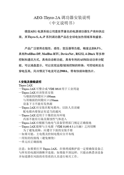
4.安装及接线说明Thyro-2AX—Thyro-2AX可整合成VDE 0610用于工业用途—Thyro-2AX应该竖直安装与墙面的间隙应≥100mm与顶墙面的间隙应≥150mm设备下方不能有发热源—Thyro-2AX应安装在配电箱内,以防人员误碰配电箱内要保证有适当的通风—Thyro-2AX适用于干燥的室内环境内部不能有污染及腐蚀性气体进入—Thyro-2AX应根据当地电气设备管理部门规定正确接地—Thyro-2AX能够与主电源(VDE 0160 6.3.1/5.88)之间切断为了避免故障,应遵守下面的安装手册—如果可能,主电缆及控制电缆应分开布线—用短的绞接线(避免缠绕)—单元应正确接地注意:如果要打开Thyro-2AX,在修理或维护前一定要确保设备已与所有的电源回路断开连接,如果做不到这样,只能由熟悉该设备并知道潜在风险的有资质的人员进行相关工作。
在紧急状态,脉冲锁不能用于安全停机。
例如在晶闸管发生短路时不能断开脉冲锁开关,对于变压器负载和控制横向控制和电源分离的,Thyro-2AX必须通过脉冲锁来进行释放,只有当电压用于电源系统时方可释放,这必须在电源无电压时进行设定。
半导体保险用于晶闸管短时的短路或过流进行保护,当轻微过载时并不立即动作,因此不适用于VDE调节规定的线路保护。

Series BDPA Adjustable Differential Pressure AlarmSpecifications - Installation and Operating InstructionsBulletin E-80-BDPAThe Series BDPA Adjustable Differential Pressure Alarm with built-in audible and visual indication is designed for overpressure, vacuum, and differential pressure applications. The scaled adjustment knob allows changes to the switching pressure to be made without a pressure gage. The BDPA is available with settings from 0.08 in w.c. (20 Pa) to 20 in w.c. (5000 Pa). The silicone diaphragm and PA 6.6 body make the Series BDPA perfect for use with air and other noncombustible gases. The Series BDPA can be used in monitoring air filters and ventilators.Use only with mediums such as air, or other noncombustible or non-aggressive gases. Otherwise operating faults or accidents may occur.Alarm FunctionWhen system pressure reaches alarm point on knob, LED will flash once every 30 seconds while alarm buzzer will sound every 60 seconds. This indication will continue until alarm condition is corrected or snooze button is pressed. If snooze button is pressed the audible alarm and LED indication will cease for a three day period. If after three days the alarm condition persists, the alarm buzzer and LED indication will restart to notify the alarm condition is still present.Mounting AlarmFirst check the pressure alarm to ascertain whether any damage is visible on the housing. If the housing is leaky because of damage, the pressure switch must not be used.Switching pressure specifications apply to vertical installation which is also the recommended position with pressure connections pointing downwards.Only if there is no potential for condensate forming can you mount the pressure switch horizontally. In this case, however, the switching values are approximately 0.08 in w.c. (20 Pa) higher as indicated on the scale. In the horizontal position, the pressure switch should be mounted ‘lying down’ only (that is to say with the electrical connections pointing upwards). Do not mount the pressure switch in a hanging position (that is to say, not ‘overhead’ with the electrical connections pointing downwards). Otherwise the device will function inaccurately.a) Mounting with Screws or Brackets1. To mount the pressure switch, L-shaped A-288 and S-shaped A-289 mounting brackets can be ordered separately. To secure the device on the rear side of the housing, only use the sheet metal screws (3.5 x 8 mm) which are supplied together with the mounting brackets. Under no circumstances must you use longer screws. Otherwise, the base of the housing could be punctured resulting in the pressure switch leaking.2. You can also mount the pressure switch directly on a wall. To do this use screws with a maximum diameter of 0.315˝ (8.0 mm), if you use the outer mounting lugs to screw the device in place. Do not tighten the screws so much that the base of the device is deformed. Otherwise, the pressure switch can be shifted out of position, or leak.Installing HosesImportant: Pressure tubing cannot be kinked. Pay particular attention to this point if you run hoses over an edge. It is better to form a loop. If the hoses are kinked, the device cannot function accurately.a) For connection to the pressure switch two fittings inherent in the housing are provided for hoses with an internal diameter of 1/4˝ (6.0 mm).1. Connect a hose with the higher pressure to socket P1 which is located on the lower section of the housing.2. Connect a hose with the lower pressure to socket P2 which is located on the middle section of the housing.After you have installed the hoses, it is absolutely essential to check them for tightness of fit at the connection points, and to make sure that they run without any kinks. Electrical ConnectionWork on electrical installations must only be carried out by electricians who are specifically trained for this purpose.1. If using a 0.275˝ (7 mm) connecting cable, you can line up the press nut, the plain washer and the sealing ring directly on the cable.2. If using a 0.393˝ (10 mm) connecting cable, you must first break the inner rubber ring out of the sealing ring directly on the cable. Then line up the press nut, theplain washer and the sealing ring on the cable.First make sure that there is no voltage on the connecting cable while you are working on the electrical connections. Otherwise, apossible electric shock may result and the connected equipment may be damaged. For cable gland models, the seal in the screw cable connection is designed for cables with alternative sheath diameters of 0.275˝ (7 mm) or 0.393˝ (10 mm). Only use these sizes – otherwise the screw cable connection cannot seal adequately.[7.5]Ø11/64[Ø4.5][P2] -+ [P1]outputinputTest/buttonPrinted in U.S.A. 9/20FR# 443824-00 Rev.4©Copyright 2020 Dwyer Instruments, Inc.Setting the Pressure RangeMake absolutely certain that there is no voltage on the electrical connections before you carry out any setting on the pressure switch. Otherwise, it could be fatal if you accidentally touch the electrical connections or the metal adjusting screw while you are performing the settings.a) Use the adjustment dial to set the pressure which should trip the alarm on during an increase of pressure.1. The indications on the dial are only correct for the vertical mounting position.2. When the pressure falls, the alarm returns to its resting position as soon as the pressure falls below the dead band.Attaching Covera) Insert the screw cable connection into the recess provided for this purpose on the housing.b) Then place the housing cover in position and screw it down evenly on to the pressure switch.Testing the SettingDo not operate the system until the housing is closed. Otherwise there is the possibility of a electric shock if you accidentally touch live parts. Check the trip and reset pressures by slowly increasing the pressure and then allowing it to fall again. To test that audible alarm and LED light are functioning properly without connected pressure, press the snooze button. The alarm buzzer and LED will activate for 1 second.Important: Observe the maximum permissible operating pressure of 40 in w.c. (10 kPa) which is indicated in the data sheet. Otherwise the pressure alarm may be damaged.MAINTENANCEUpon final installation of the Series BDPA Adjustable Differential Pressure Alarm, no routine maintenance is required other than possible battery replacement if used. Roughly one week before the battery goes dead, the LED will pulse 3 times once every minute while every fifth minute the alarm buzzer will synchronize with the LED giving off 3 short signals notifying of a low battery. A periodic check of system calibration is recommended. The Series BDPA is not field serviceable and should be returned if repair is needed (field repair should not be attempted and may void warranty). Be sure to include a brief description of the problem plus any relevant application notes. Contact customer service to receive a return goods authorization number before shipping.24 VAC/VDC line power wiring: Switch output connectedBattery acts as back-up power24 VAC/VDC line power: Switch output connected Seperate power for supply with switch loop24 VAC/VDC power wiring Battery acts as back-up powerRemote snooze wiringShown battery powered can be combined with line powerBattery power: Switch output connectedWIRING DIAGRAMS。


Filter regulatorII 2GD c TX XOperating instructions (Original instructions)80736002017-04[8073602]Filter regulator LFR-…-EX4English......................................NoteTechnical data for the product can have different values in other documents.During operation in an explosive atmosphere, the technical data of this document always have priority.1About this documentThis document describes the use of the above-mentioned product.1.1Applicable documentsFor all available product documentation è /pk2Safety2.1Intended useThe filter regulator LFR-…-EX4 regulates the compressed air in the subsequent string to the set outlet pressure. The LFR-… thereby smoothes out pressure fluctuations. The outlet pressure p2 can be set within the pressure regulation range è Technical data.2.2General safety informationThe device can be used under the stated operating conditions in zone 1, explosive gas atmospheres, and in zone 21, explosive dust atmospheres.The product may only be used in its original status without unauthorized modifications.Only use the product if it is in perfect technical condition. Carry out all work outside potentially explosive areas.Comply with all applicable national and international regulations. Observe the specifications on the product labelling.Take into consideration the ambient conditions at the location of use. Earth the device via the grounding screw.NoteLabel X: special conditionsDanger of electrostatic discharge.Ambient temperature T18: 20 °C ≤ Ta ≤ +80 °C Ambient temperature T3: 40 °C ≤ Ta ≤ +80 °CNoteIdentification TX: Special conditionsThe device does not generate heat itself.MediaOnly use media in accordance with the specifications è Technical data.3Further information–Accessories è /catalogue –Spare parts è /spareparts –Documents and literature è /sp4ServiceConsult your regional Festo contact if you have any technical queries è 5Product overview 5.1Product variantsTemperature class T18: -20°C … +80°C Connection TypePart number¼"LFR-1/4-D-5M-O-MIDI-T18-EX44772764¼"LFR-1/4-D-O-MIDI-T18-EX44772765¼"LFR-1/4-D-16-5M-O-MIDI-T18-EX44772766¼"LFR-1/4-D-16-O-MIDI-T18-EX44772767¼"LFR-N1/4-D-5M-O-MIDI-T18-EX44772772¼"LFR-N1/4-D-O-MIDI-T18-EX44772773¼"LFR-N1/4-D-16-5M-O-MIDI-T18-EX44772774¼"LFR-N1/4-D-16-O-MIDI-T18-EX44772775Fig. 1Temperature class T18: -20°C … +80°C Connection TypePart number½"LFR-1/2-D-5M-O-MIDI-T18-EX44772768½"LFR-1/2-D-O-MIDI-T18-EX44772769½"LFR-1/2-D-16-5M-O-MIDI-T18-EX44772770½"LFR-1/2-D-16-O-MIDI-T18-EX44772771½"LFR-N1/2-D-5M-O-MIDI-T18-EX44772776½"LFR-N1/2-D-O-MIDI-T18-EX44772777½"LFR-N1/2-D-16-5M-O-MIDI-T18-EX44772778½"LFR-N1/2-D-16-O-MIDI-T18-EX44772779Fig. 2Temperature class T3: -40°C … +80°C Connection TypePart number¼"LFR-1/4-D-5M-O-MIDI-T3-EX45271792¼"LFR-1/4-D-O-MIDI-T3-EX45271793¼"LFR-1/4-D-16-5M-O-MIDI-T3-EX45271794¼"LFR-1/4-D-16-O-MIDI-T3-EX45271795½"LFR-1/2-D-5M-O-MIDI-T3-EX45271796½"LFR-1/2-D-O-MIDI-T3-EX45271797½"LFR-1/2-D-16-5M-O-MIDI-T3-EX45271798½"LFR-1/2-D-16-O-MIDI-T3-EX45271799¼"LFR-N1/4-D-5M-O-MIDI-T3-EX45271800¼"LFR-N1/4-D-O-MIDI-T3-EX45271801¼"LFR-N1/4-D-16-5M-O-MIDI-T3-EX45271802¼"LFR-N1/4-D-16-O-MIDI-T3-EX45271803½"LFR-N1/2-D-5M-O-MIDI-T3-EX45271804½"LFR-N1/2-D-O-MIDI-T3-EX45271805½"LFR-N1/2-D-16-5M-O-MIDI-T3-EX45271806½"LFR-N1/2-D-16-O-MIDI-T3-EX45271807Fig. 35.2FunctionThe filter regulator LFR-… removes dirt particles and condensate. The outlet pressure can be adjusted within the pressure range.6Assembly and installationFig. 4Fig. 1Fig. 21Indication of flow direction 2Blanking screw 3Sub-base4Threaded bolt FRB-D 5Spacer bolt 6Seal7Filter bowl8Grounding ScrewFig. 16.1Filter regulator1.Observe flow direction 1 to2.–Observe the direction of the arrow 1 on the device.2.Place the device at least 80 mm below the filter bowl.3.Position the device vertically (±5°).When assembling filter combinations, observe the sequence along the flow direction.6.2Mounting the pressure gauge 1.Remove the blanking screw 2.2.Screw the pressure gauge MA into the LFR-… as far as its stop.–The pressure gauge seal is pre-assembled on the threaded connection journal.6.3Assembly with an existing service unit of the same size1.Remove sub-base 3 from both devices on the sides to be fitted together.2.Screw the threaded bolts 4 (order separately, if needed) into the basic unit.3.Remove the sub-base from the respective add-on device and drive out the corresponding spacer bolts 5 (drive out in the flow direction).4.Mount the add-on device with the sub-base. There must be one seal 6 each between the individual devices as well as the sub-base.6.4Assembly to pneumatic actuatorScrew the connectors into the pneumatic connections using a suitable sealing material.7Commissioning WarningThe discharge of electrostatically charged parts can lead to ignitable sparks. Prevent electrostatic discharge through the use of appropriate installation and cleaning measures.Include the device in the system’s potential equalisation. Operation without the rotary knob is not permissible.Use the knurled nut only for installation with an earthed mounting bracket.When using other mounting components, remove the knurled nut.1.Unlock the rotary knob. To do this, pull the rotary knob away from the housing.2.Turn the rotary knob closed.–Direction "—"3.Pressurise the system slowly.4.Open the rotary knob until the desired pressure is displayed on the pressure gauge.–Direction "+"–Compressed air range è Technical data.5.Lock the rotary knob. To do this, press the rotary knob towards the housing.NoteThe inlet pressure p1 is at least 1 bar higher than the outlet pressure p2.NoteStrong charge-generating processes can charge non-conductive layers and coatings on metal surfaces.NoteEscaping exhaust air can swirl up dust and create an explosive dust atmosphere.NoteParticulate matter in the compressed air can cause electrostatic charges.8OperationObserve the operating conditions.Observe the information in the general operating instructions. Comply with permissible limit values è Technical data.Draw in operating medium outside potentially explosive areas.9Malfunctions MalfunctionPossible causeRemedyLow flow rate(operating pressure breaks down with air consumption)Filter cartridge is dirty.Replace the filter cartridge.Restriction between shut-off valve and service unit Check tubing.Pressure increases above the set working pressureValve disc defective at sealing seatReplace device.Blowing noise can be heard at the rotary knobValve seat damaged Replace device.Blowing noise can be heard at the drain screwDrain screw leakingTighten or Replace device10MaintenanceCondensate drain can be opened in periodical intervals based on the field of application.Perform maintenance only outside potentially explosive areas.When replacing individual devices in a service unit or when changing the configuration: After assembly, check the flow resistance between the earthing screws on the left-hand and right-hand sub-base è Technical data.Replacing the filter cartridge 1.Exhaust the device.2.Unscrew the filter bowl.3.Unscrew the filter plate.4.Remove the used filter cartridge.5.Place a new filter cartridge on the filter plate and secure it in place.6.Tighten the filter bowl è Fig. 67.Recommission è Chapter 4.Cleaning1.Clean the device, if required, with a soft cloth.Permissible cleaning agents:–Soap suds (max. +60 °C)–Petroleum ether (free of aromatic compounds)11Technical data Operating conditionsOperating medium Compressed air in accordance with ISO 8573-1:2010:[-:9-]Operating pressure p1bar1 (20)Pressure regulation range p2LFR-...D-...O-MIDI-...EX4bar 0.5 (12)LFR-…D-16-…O-MIDI-…EX4bar 0.5 … 16 (between +60 °C … +80 °C: p2 = max. 12)Temperature of medium/ambient temperature/storage temperatureLFR-…-D-…-O-MIDI-T18-EX4°C 20 … +80LFR-…-D-…-O-MIDI-T3-EX4°C40 … +80Mounting position vertical ± 5°Flow direction see direction of arrow on the deviceMaterials Housing Zn SealNBR Filter cartridgePE Blanking screw, rotary knob POMKnurled nut, outlet, filter bowlAl, coated (CRC 3/KBK 3)Fig. 2。

ALARM_00 :NH3流量计报警!原因:测量NH3的传感器损坏!处理:更换新NH3流量计,或送到SULZER METAPLAS 进行维修。
ALARM_01 :T4温度报警!原因:温度的实际值过高,温控和热电偶中间的连接中断。
处理:a提高温度的设定点或冷却炉体。
b检查热电偶插头或插头连接。
ALARM_02 :等离子发生故障报警!原因:电源开关或主接触器损坏!处理:检查i(30) i(31) o(2) ,备注:只有受过专业培训的人才能处理!ALARM_03 :过电压报警!原因:过电压,直流电压超过800V!处理:消除后又重复出现报警,报告维修人员。
备注:只有受过专业培训的人才能处理!ALARM_04 :过电流报警!原因:脉冲单元输入电流过高。
处理:消除后又重复出现报警,报告维修人员。
备注:只有受过专业培训的人才能处理!ALARM_06 :程序中断报警!原因:a 显示“process stop”。
b 由于产生报警导致程序中断。
处理:消除警报,按“process start”。
ALARM_07:在PNC中炉子中空压力过高。
原因:a 中空泵坏了。
b 有泄漏。
c 炉子没盖好。
d 气阀i(2)顺序不正确。
处理:检查中空泵好坏,检查炉子有没有泄漏,重新盖炉子,检查压力开关。
ALARM_08 :冷却水不足报警。
原因:冷却水不足,压力达不到。
处理:增压,打开阀门加大水流量。
ALARM_10 :H2报警。
原因:压力开关(GS3)反馈没压力。
处理:检查气源。
ALARM_11 :CO2报警。
原因:CO2压力开关反馈没压力!处理:检查气源。
ALARM_12 :N2报警。
原因:压力开关(GS1)反馈没压力。
处理:检查气源。
ALARM_13:主机报错。
原因:主机温度过高!处理:检查机柜空调,检查机柜的通风情况,关机等温度降下来重新开启。
ALARM_14 :超出过程时间报警。
原因:实际时间超出过程时间。
处理:检查过程延迟的原因,重新设定时间。
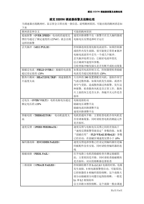
派克SSD590调速器报警及故障处理当调速器出现跳闸时,显示屏会立即出现一条信息,说明跳闸原因,可能出现的跳闸消息如报警信息:当跳闸发生时,MMI上将出现一个报警信息,“报警状态”(ALARM STATUS)菜单中同时显示跳闸信息。
“正常存储”(HEALTH STORE)和“正常字”(HEALTH WORD)显示十六进制值的参数信息,或者当出现一个以上的报警时显示十六进值的总和。
这样,单一的值可能代表着一个报警或多个报警。
注:十六进制指的是在计数时以16为基数而不是以10为基数的通常算法。
所使用的16上“数字“是从0—9 A—F,因此,一个8位字节由00 到FF范围内的两个字符来表示,而一个16位字则由0000到FFFF范围内的四个字符来表示。
最后报警(LAST ALARM)“最后报警”所显示的是已经显示过的最后报警信息。
要将这一参数复位,只需简单的按一下向下按钮就可以清除报警。
也可以将辅助电源开关关闭后再开启,显示示“无有效的报警”(NO ACTIVE ALARMS).正常字(HEALTH WORD)这一参数用来持续监控调速器的状态,当添加或清除报警时,显屏将立即更新,显示这些报警的十六进制总和。
当“启动”C3 输入为高电平,且当没有跳闸条件存在时,其值回复到0X0000正常存储(HEALTH STORE)它显示的是引起跳闸的第一次报警的十六进制值。
当“启动”C3 输入为高电平,且当没有跳闸条件存在时,其值回复到0X0000 。
当一个以上的跳闸同时显示时,跳闸字便只相加在一起形成显示值。
在每个数字内,10-15之间的值用A到F字母显示。
例如,当“正常字”参数为01A8时,它代表第三位为1,在第二位为8和2,(8+2=10,显示为A),第一位为8.反过来,它代表处于活动状态的跳闸“励磁故障”(FIELD FAILED)、“编码器故障”(ENCODER FAILED)、“过电压”(OVER VOLTS)和“散热器跳闸”(HEATSINK TRIP).对于调速器不能解决的报警,我们可以通过禁止报警的方式,把某个无关紧要的报警屏蔽。
610/611/612可调设定点气体压差开关/报警器应用和特点用于监测空气等非可燃、非腐蚀气体的过压、真空和压差状态。
其中,610仅带有干接点开关输出;611为报警器,提供本地声光报警;612既有干接点开关输出,还带有本地声光报警功能。
611/612有静音按键,用于消除声音报警。
此外,610具有高达IP65的防护等级,可以室外使用。
技术指标量程范围:20~300Pa ,50~500Pa 等可选,详见选型表最大压力限制:10kPa(0~50°C)工作温度:-30~70°C(610)或-10~50°C(611/612),介质及环境存储温度:-40~70°C压力连接:内径6.0mm 塑料软管,“+”为高压端,“-”为低压端开关寿命:106次以上最大开关频率:6次/分钟重复性:±2%电气特性:型号610611612电源-85~250VAC 9~28VAC/DC 声光报警-红/绿色LED ,蜂鸣器/静音键开关输出SPDT2A/250VAC 1A/30VDC-SPST3A,30VDC/ACEMCGB14536.1/GB14536.7,IEC60730-1/IEC60730-2-6电气连接螺丝端子材质:壳体阻燃PC (UL94V-0),硅胶膜片,银合金触点重量:610:130g ,611/612:155g防护:610:标准型IP54,可选IP65,在选型后加后缀-S611/612:IP40认证:CE ,RoHS安装:垂直,压力接口向下。
此为开关校准位置。
如必须水平安装时,实际设定点比刻度点加20Pa(封盖向上)或减约10Pa(封盖向下),详见使用说明书选型表型号610可调设定点气体压差开关611可调设定点气体压差报警器(声光)612可调设定点气体压差开关,带声光报警量程范围020-300Pa 150-500Pa 2100-1000Pa 30.5-2.5kPa 工程单位0Pa 7mbar 8inch WC 9mm WC回差表型号可调量程范围工厂设定回差61x.020-300Pa 10±5Pa 61x.150-500Pa 20±8Pa 61x.2100-1000Pa 50±15Pa 61x.30.5-2.5kPa100±30Pa工厂设定回差,客户不能自行调整。
P+F报警设定器使用说明1.功能和面板介绍报警设定器的型号:KF**-CRG2-(EX)1.D,该报警设定器除具备隔离安全栅的功能外,还具备报警功能。
下图为该型号报警设定器的面板,主要的指示和操作都将在这个面板中完成。
指示灯CHK红色表示:设备故障;指示灯PWR绿色表示:设备供电正常;指示灯OUT1黄色表示:设备1被激活;指示灯OUT2黄色表示:设备2被激活;2.安装接线和连接说明上图为该报警设定器的侧面图形,在安装过程中,现场过来的4-20mA信号接在左侧“1-3”端子上,如果现场为配电信号则接在1,3端子上(1+、3-),如果现场为不配电信号则接在2,3端子上(3+、2-)。
图形的右侧有四个区域,其中23,24端子(23+、24-)给报警器提供24V电源;III区的7,8端子(8+、7-)去DCS系统柜相应的端子板上;I、II区则是输出去ESD的两个DI信号。
信号线分别接在10,11(11+、10-)以及16,17端子(17+、16-)。
I、II区对应于OUT1和OUT2指示灯。
因为一个变送器对应的信号可能存在高报(低报)或者高高报(低低报)两个报警限,所以有两个区,也对应有两个设备被激活的情况。
3.参数设置在报警设定器参数设置过程中,面板上有四个重要的按钮:“UP、DOWN、ESC、OK”。
同时摁住“OK”与“ESC”长达一秒,将进入参数设置的主菜单。
主菜单内有:输入(INPUT),输出(OUTPUT),单位(UNIT),服务(SERVICE)四个可操作项,这里只需要设置输入、输出以及单位即可。
通过“UP”或“DOWN”按钮,选择“UNIT”选项,点击“OK”,则进入单位设置,选择“4-20mA”,点击“OK”,完成单位的设置。
“INPUT”中存在一个线性检测“Line monitor”,点击“OK”,进行设置。
通过改变“LB”、“SC”可以对短路和断路进行检测。
如果LB选为ON,当输入信号小于0.2mA时,表示断路;如果SC选为ON,当输入信号大于22mA时,表示短路。
富安时调功器报警说明富安时调功器是一种用于监测和控制电力系统的设备,它可以检测电力系统中的故障和异常情况,并及时报警。
在电力系统中,电能的传输和分配是一个复杂的过程,如果系统中存在故障或异常,往往会导致电力供应的中断或不稳定,给生产和生活带来严重影响。
因此,及时发现和处理电力系统中的问题是非常重要的。
富安时调功器可以通过监测电力系统中的电压、电流、频率等参数,来判断系统是否正常运行。
当电力系统中出现异常情况时,富安时调功器会根据预设的报警条件发出警报,通知相关人员进行处理。
这样可以及时发现和解决电力系统中的问题,保证电力的稳定供应。
富安时调功器的报警功能是其最重要的特点之一。
它可以通过不同的报警方式来提醒人们注意电力系统的异常情况,比如声音报警、光闪报警、短信报警等。
这样,即使在没有人员在现场的情况下,也能及时发现电力系统中的问题,并采取相应的措施。
富安时调功器的报警功能可以应用于各种电力系统,比如发电厂、变电站、配电室等。
它可以监测电力系统的各种参数,比如电压、电流、频率、功率因数等,通过对这些参数的监测和分析,可以判断系统是否正常运行。
当系统出现异常情况时,富安时调功器会发出警报,通知相关人员进行处理。
富安时调功器报警功能的设置也是比较灵活的。
用户可以根据实际需要,设置不同的报警条件和报警级别。
比如可以设置当电压超过或低于一定范围时报警,当电流超过或低于一定范围时报警,当频率超过或低于一定范围时报警等。
这样可以根据不同的需求,灵活地进行报警设置。
富安时调功器报警功能的应用可以提高电力系统的安全性和可靠性。
通过及时发现和处理电力系统中的问题,可以避免出现更大的事故和损失。
同时,它也可以提高电力系统的运行效率,减少能源的浪费。
因此,富安时调功器报警功能的应用具有重要的意义和价值。
富安时调功器报警功能是一种重要的电力系统监测和控制设备。
它可以通过监测电力系统中的参数,及时发现和处理系统中的故障和异常情况,保证电力的稳定供应。
富安时调功器报警说明
介绍
富安时调功器是一种用于调节电力系统功率因数的装置。
它能够控制电力系统中的电容器或电感器的连接和断开,以改变电路的等效电阻和电感,从而调整功率因数的大小。
然而,在使用富安时调功器时,有时会出现报警情况,本文将探讨富安时调功器报警的原因和处理方法。
报警原因
富安时调功器报警通常有多种原因,以下是一些常见的情况:
1. 过载保护
当电力系统中的负载超过调功器的额定容量时,调功器会发出报警信号。
这可能是由于负载突增、过流等原因导致的。
2. 电源异常
调功器需要稳定的电源供应才能正常工作。
如果电源电压过高或过低,或者电源发生瞬时中断,调功器可能会出现报警。
3. 温度过高
调功器在工作过程中会产生一定的热量,如果散热不良或环境温度过高,调功器的温度会升高。
当温度超过设定的安全阈值时,调功器会进行自我保护并发出报警信号。
4. 系统故障
如果调功器内部的电子元器件出现故障,或者控制系统发生故障,调功器会自动检测到问题并进行报警。
报警处理
在调功器报警时,需要及时采取措施处理问题,以下是处理报警的方法:
1. 检查负载
首先,需要检查电力系统中的负载情况。
如果负载超过调功器的额定容量,应该考虑减少负载或增加调功器的容量。
如果负载是突然增加的,可能是由于设备故障或其他原因导致,需要进行相应维修和处理。
2. 检查电源
确保调功器的电源供应正常稳定。
检查电源电压是否在额定范围内,如果不是,需要检修电源系统。
同时,还应检查电源线路是否接触良好,没有松动或短路。
3. 散热处理
如果调功器温度过高,要及时采取散热措施降低温度。
可以增加散热器、风扇等散热装置,或者将调功器安装在通风良好的地方。
如果环境温度过高,可以考虑降低室温或者增加空调设备。
4. 维修和更换
如果调功器出现内部故障,需要进行维修或更换故障部件。
在维修过程中,要确保操作人员具有相关技术知识和操作经验,以免造成更大的损害。
注意事项
在处理富安时调功器报警时,还需要注意以下几点:
1.定期检查和保养调功器,确保其正常工作。
遵循调功器的使用说明,按照规
定进行日常维护。
2.注意调功器的额定容量,避免负载超过调功器的承载能力。
3.使用优质的电源和线路,保证调功器的供电正常稳定。
4.定期监测调功器的温度,及时清理散热装置,在需要时增加散热设备。
5.在处理调功器报警时,要谨慎操作,遵循相关安全操作规程。
6.如果不熟悉操作调功器或无法解决问题,应及时联系专业人员进行维修。
在正常使用和维护的情况下,富安时调功器可以有效控制功率因数,提高电力系统的效率和稳定性。
当出现报警时,及时处理问题,可以确保调功器的正常工作,保障电力系统的安全运行。