伊顿威格士伺服阀
- 格式:pdf
- 大小:328.02 KB
- 文档页数:22

风力发电机组电液伺服系统简介一、概述:风力发电机组的液压伺服系统,主要用于变浆距风力发电机组的变浆控制装置、安全浆距控制装置、偏航驱动和制动装置、停机制动装置提供液压驱动力及控制,实现风力发电机组的转速控制、功率控制,同时也制控机械刹车机构。
根据自然风速、风向,液压伺服系统自动调节发电机组在稳定的电压和频率下运行发电,并对恶劣气候实施自动安全保护。
二、风力发电机组电液伺服液压系统特点:1、可实现大范围的无级调速(调速范围达2000:1),即能在很宽的范围内很容易地调节力与转矩;2、控制性能好,对力、速度、位置等指标能以很高的响应速度精确地进行控制。
很容易实现机器的自动化,不仅可实现更高程度的自动控制过程,而且可以实现遥控。
3、体积小、重量轻、运动惯性小、反应速度快,动作可靠,操作性能好。
4、可自动实现过载保护。
一般采用矿物油作为工作介质,相对运动面可自行润滑,使用寿命长。
5、可以方便地根据需要使用液压标准元件、灵活地构成实现任意复杂功能的系统。
6、采用高性能比例伺服阀,提高抗污染能力。
三、电液伺服系统的基本组成1、动力元件动力元件的作用是将原动机的机械能转换成液体(主要是油)的压力能,是指液压系统中的油泵,向整个液压系统提供压力油。
液压泵的常见结构形式有齿轮泵、叶片泵和柱塞泵。
2、控制元件控制元件(即各种液压阀)其作用是在液压系统中控制和调节液体的压力、流量和方向,以满足执行元件对力、速度和运动方向的要求。
该电液伺服系统的主要元件为带位置反馈的高性能比例伺服阀。
3、执行元件执行元件是把系统的液体压力能转换为机械能的装置,驱动外负载做功。
旋转运动用液压马达,直线运动用液压缸,摆动用液压摆动马达。
油缸、马达有位置传感器与控制阀构成反馈控制。
4、辅助元件辅助元件是传递压力能和液体本身调整所必需的液压辅件,其作用是储油、保压、滤油、检测等,并把液压系统的各元件按要求连接起来,构成一个完整的液压系统。
辅助元件包括油箱、蓄能器、滤油器、传感器、油管及管接头、密封圈、压力表、油位计、油温计等。

世界9 大液压配件品牌世界液压配件品牌第1:派克(PARKER) 派克汉尼汾公司是一家总部位于美国俄亥俄州的世界一流的工业企业,主要制造流体传动元器件及系统,用于控制各种机械和其他设备的传动、流量和压力。
派克提供1,400 多条产品线,用于1,000 多种工程机械、工业和航空航天领域内的项目。
派克是唯一一家能够给客户提供液压、气动、密封、机电一体化和计算机传动控制解决方案的制造商。
世界液压配件品牌第2:力士乐(Rexroth) (德国) 博世力士乐生产先进的工业液压元件与系统,配合了微电子技术,令传动有力而精确。
其电子传动与控制产品及系统永远走在科技前端,为不同应用提供最佳的解决方案。
在线性传动与组装技术方面,力士乐把两种技术之优点融合,满足了客户不同的要求。
世界液压配件品牌第3:西德福(STAUFF) 中国西德福是西德福国际公司独资在华建立的企业集团。
西德福国际贸易(上海)有限公司是该企业集团的成员公司之一,在上海浦东外高桥保税区登记注册。
主要从事西德福国际公司的产品在中国国内市场上的推广与销售,为客户提供技术咨询和售后服务。
世界液压配件品牌第4:贺德克(HYDAC)HYDAC贺德克德国HYDACTech no logy GmbH专业生产用于流体过滤技术、液压控制技术、电子测量技术的元件和装置,是世界著名的过滤器、蓄能器、液压阀、电子产品、管夹、电磁铁、液压系统总成等产品的液压件制造商。
HYDA(产品的应用范围十分广泛,几乎覆盖各行各业,尤其在冶金工业、汽车工业、电力设备、化工、工程机械、造纸工业、造船工业以及机床制造等领域都得到广泛应用。
世界液压配件品牌第5:阿托斯(Atos)Atos 是世界领先的电液元件制造商,具有先进的技术能通过带电子器件的集成式液压无件提高现代化机器的性能。
世界液压配件品牌第6:爱力克(Aeroquip)Aeroquip 爱力克Aeroquip 是伊顿集团流体动力部门旗下的一个全球知名的液压品牌,其主要产品包括液压软管及接头等。


电液伺服阀的工作原理∙电液伺服阀由力矩马达和液压放大器组成。
力矩马达工作原理磁铁把导磁体磁化成N、S极,形成磁场。
衔铁和挡板固连由弹簧支撑位于导磁体的中间。
挡板下端球头嵌放在滑阀中间凹槽内;线圈无电流时,力矩马达无力矩输出,挡板处于两喷嘴中间;当输入电流通过线圈使衔铁3左端被磁化为N极,右端为S极,衔铁逆时针偏转。
弹簧管弯曲产生反力矩,使衔铁转过θ角。
电流越大θ角就越大,力矩马达把输入电信号转换为力矩信号输出。
前置放大级工作原理压力油经滤油器和节流孔流到滑阀左、右两端油腔和两喷嘴腔,由喷嘴喷出,经阀9中部流回油箱力矩马达无输出信号时,挡板不动,滑阀两端压力相等。
当力矩马达有信号输出时,挡板偏转,两喷嘴与挡板之间的间隙不等,致使滑阀两端压力不等,推动阀芯移动。
功率放大级工作原理当前置放大级有压差信号使滑阀阀芯移动时,主油路被接通。
滑阀位移后的开度正比于力矩马达的输入电流,即阀的输出流量和输入电流成正比;当输入电流反向时,输出流量也反向。
滑阀移动的同时,挡板下端的小球亦随同移动,使挡板弹簧片产生弹性反力,阻止滑阀继续移动;挡板变形又使它在两喷嘴间的位移量减小,实现了反馈。
当滑阀上的液压作用力和挡板弹性反力平衡时,滑阀便保持在这一开度上不再移动。
电液伺服阀的分类∙ 1 按液压放大级数可分为单级电液伺服阀,两级电液伺服阀,三级电液伺服阀。
2 按液压前置级的结构形式,可分为单喷嘴挡板式,双喷嘴挡板式,滑阀式,射流管式和偏转板射流式。
3 按反馈形式可分为位置反馈式,负载压力反馈式,负载流量反馈式,电反馈式等。
4 按电机械转换装置可分为动铁式和动圈式。
5 按输出量形式可分为流量伺服阀和压力控制伺服阀。
电液伺服阀运转不良引起的故障∙ 1 油动机拒动在机组启动前做阀门传动试验时,有时出现个别油动机不动的现象,在排除控制信号故障的前提下,造成上述现象的主要原因是电液伺服阀卡涩。
尽管在机组启动前已进行油循环且油质化验也合格,但由于系统中的各个死角的位置不可能完全循环冲洗,所以一些颗粒可能在伺服阀动作过程中卡涩伺服阀。

vickers柱塞泵威格士液压柱塞泵美国威格士vickers柱塞泵美国伊顿威格士eaton vickers 液压柱塞泵液压柱塞泵靠气压供油的液压油箱,在每次启动机器后,必须等液压渍箱达到使用气压后,才能操作机械。
直轴斜盘式柱塞泵分为压力供油型的自吸油型两种。
压力供油型液压泵大都采用有气压的油箱,也有液压泵本身带有补油分泵向液压泵进油口提供压力油的。
自吸油型液压泵的自吸油能力很强,无需外力供油。
对于自吸油型柱塞泵,液压油箱内的油液不得低于油标下限,要保持足够数量的液压油。
液压油的清洁度越高,液压泵的使用寿命越长。
vickers径向柱塞泵径向柱塞泵可分为阀配流与轴配流两大类。
阀配流径向柱塞泵存在故障率高、效率低等缺点。
国际上70、80年代发展的轴配流径向柱塞泵克服了阀配流径向柱塞泵的不足。
由于径向泵结构上的特点,陕定了轴配流径向柱塞泵比轴向柱塞泵耐冲击、寿命长、控制精度高。
变量行程短泵的变量是在变量柱塞和限位柱塞作用下,改变定子的偏心距实现的,而定于的最大偏心距为5—9mm(根据排量大小不同),变量行程很短。
且变量机构设计为高压操纵,由控制阀进行控制。
故该泵的响应速度快。
径向结构设计克服了如轴向柱塞泵滑靴偏磨的问题。
使其抗冲击能力大幅度提高。
vickers轴向柱塞泵轴向柱塞泵是活塞或柱塞的往复运动方向与缸体中心轴平行的柱塞泵。
轴向柱塞泵是利用与传动轴平行的柱塞在柱塞孔内往复运动所产生的容积变化来进行工作的。
由于柱塞和柱塞孔都是圆形零件,加工时可以达到很高的精度配合,因此容积效率高,运转平稳,流量均匀性好,噪声低,工作压力高等优点,但对液压油的污染较敏感,结构较复杂,造价较高。
vickers直轴斜盘式柱塞泵直轴斜盘式柱塞泵分为压力供油型的自吸油型两种。
压力供油型液压泵大都采用有气压的油箱,也有液压泵本身带有补油分泵向液压泵进油口提供压力油的。
自吸油型液压泵的自吸油能力很强,无需外力供油。
靠气压供油的液压油箱,在每次启动机器后,必须等液压渍箱达到使用气压后,才能操作机械。

Flow - lpm P r e s s u r e D r o p - p s i5ESV9-10-E - Proportional Solenoid Valve4-way, 3-position, screw-in cartridge, proportional solenoid valve Up to 22 L/min (5.8 USgpm) • Up to 250 bar (3600 psi)DescriptionThe ESV9 with E spool is a proportional four-way,three-position, direct acting, spool type solenoid valve with all ports closed in the de-energized position. This valve is ideal for moderate flow applications where an actuator needs to be con-trolled proportionally in both directions and stopped in any position.OperationIn the de-energized(center) position, all ports are blocked. When solenoid A is energized, flow is directed from port 3 to port 2 and from port 4 to port 1. Port 1 is not intended to be used as an inlet.When solenoid B is energized, flow is directed from port 3 to port 4 and from port 2 to port 1. Port 1 is not intended to be used as an inlet.Features•Highly engineered components•Compact design with low pressure drop•Designed for optimized linearity and hysteresis •IP69K Large ToughCoils™ compatible•Optional manual override •Industry standard cavity toolPerformance DataProfile ViewA - Port 3 to port 2B - Port 3 to port 4C - Port 4 to port 1D - Port 2 to port 1“Coil B”3421COIL B3124COIL A510152025Coil B Coil A2.00 1.501.000.500.000.50 1.00 1.502.00F l o w (l p m )Current (A)ESV9-10-F - Proportional Solenoid Valve4-way, 3-position, screw-in cartridge, proportional solenoid valve Up to 22 L/min (5.8 USgpm) • Up to 250 bar (3600 psi)DescriptionThe ESV9 with F spool is a proportional four way, three position, direct acting, spool type solenoid valve. In the de-energized condition Port 2 and 4 are open to tank with the inlet port 3 blocked. This valve is ideal formoderate flow applications where an actuator needs to be moved in both directions and stopped in any position while allowing the service ports to decay to tank pres-sure in the de-energized condition.OperationIn the de-energized (cen-ter) position, port 1, port 2, and port 4 are open to each other while port 3 is blocked. When solenoid A is energized, flow isdirected from port 3 to port 2 and from port 4 to port 1. When solenoid B is energized, flow is directed from port 3 to port 4 and from port 2 to port 1.Features•Highly engineered components•Compact design with low pressure drop•Designed for optimized linearity and hysteresis •IP69K Large ToughCoils™ compatible•Optional manual override •Industry standard cavity tool .Performance DataProfile View Pressure DropA - Port 3 or port 2 energizedB - Port 3 to port 4 energizedC - Port 2 or port 1 energizedD - Port 2 to port 1 de-energizedFlow - Ipm 0510152025303540051015202530354045505560ABC E DFP r e s s u r e D r o p - b a r“Coil B”“Coil A”342124COIL BCOIL A510152025Coil B Coil A2.00 1.501.000.500.000.501.001.502.00F l o w (l p m )Current (A)E - Port 4 to port 1 energizedF - Port 4 to port 1 de-energizedFlow vs. Current at 10 bar ∆PUp to 22 L/min (5.8 USgpm) • Up to 250 bar (3600 psi)Model Code1ESV93*4*5*–––––1 FunctionESV9 - Proportional solenoid valve2 S ize10 - 10 size3 S eal MaterialBlank - Buna-N V - Viton®210Code Port SizeHou s ing NumberAluminium Steel0 Cartridge only A2G 1/4” BSPP 02-185804A3G 3/8” BSPP 02-185805A6H SAE 6 02-185802A8H SAE 8 02-185803S2G 1/4” BSPP 02-175139S3G 3/8” BSPP 02-175140S6T SAE 6 02-175137S8TSAE 802-175138See section J for housing details.6 Housing Material and PortsWARNINGAluminum housingscan be used for pres-sures up to 210 bar (3000 psi). Steel housings must be used for operating pressures above210 bar (3000 psi).EF4 Spool Center ConditionCOIL B3124COIL A24COIL BCOILA6***5 Manual Override Option0 - No manual overrideM - Manual override, push pull typeFor valve dimensions with manual override, see pages B873.7 Coil Voltage and T ype000 - No coil012D - 12V DC without diode 024D - 24V DC without diode 012B - 12V DC with diode 024B - 24V DC with diode8 Connection T ypeBlank - No coilN - Deutsch male, DT04-2P , integrated G - DIN 43650 W - Flying leadY - Amp Jr (DC Only) Mating Connector: AMP 963040-3 or equivalentD0 - MetriPackR 150 Male, Integrated (DC Only) Mating Connector: Delphi 12052641See Section C for coil details .1 T hese model digits are not stamped onthe valve.10 Coil Special Feature00 - None11 Valve Special Features 100 - None(Only required if valve has special features omitted if "00".)12 Design CodeA - Design code 009 Coil S eriesBlank - No coil L - L Series Large ToughCoils™ 28 W11**12A10**8*9*7****BUp to 22 L/min (5.8 USgpm) • 250 bar (3000 psi)Dimensions mm (inch)Torque cartridge in aluminum housing 47 - 54 Nm (34.7 - 39.8 ft. lbs.) and 56 - 62 Nm (41.3 - 45.7 ft. lbs. ) in a steel housingValve is shown with large tough coil.Note: The ESV9-10 is shipped with a spacer (6038409-001) to be used with the Large Tough Coil. Spacer is not needed when used with the EN490 coil.When solenoid valve isordered without coils, it will be supplied with coil spacer and coil nut.Spare PartsCoil Nut for MO 6038813-001Coil Nut without MO 02-148332Coil Spacer6038409-001WARNINGMaintain 5-8 Nm (4-6 ft lbs) maximumtorque on valve tube nut. Over tightening may cause valve failure.1。

威格士Vickers压力控制阀工作原理
Vickers压力控制阀靠在阀芯端部施加压力克服由于手动调整机构加载的弹簧而动作。
在平衡阀和顺序阀中,阀芯靠弹簧偏置使流量不能通过阀。
当阀芯端部控制压力所产生的力超过主弹簧力时,阀芯运动使流量通过阀。
在减压阀中,流道是常通的,在控制压力超过阀的手动设定值时才关闭。
靠溢流功能来防止减压管路中过高的压力。
压力调整选项是螺杆/锁紧螺母、手动旋钮和带锁的千分尺.
Vickers压力控制阀工作原理在“截流”状态(即在减压出口不需要流量)下,从减压管路流入T 管路的典型的泄漏流量。
为了保持减压出口压力,在进口管路P 中必须提供该泄漏
流量。
W调整器调整阀的设定值时,松开锁紧螺母并且转动调整器螺杆,顺时针转提高压力,逆时针转降低压力。
调整完毕重新拧紧锁紧螺母。
H调整器调整阀的设定值时,松开锁紧螺母并且转动旋钮,顺时针转提高压力,逆时针转降低压力。
调整完毕重新拧紧锁紧螺母。
K调整器调整阀的设定值时,必须插入钥匙并转动。
顺时针转动旋钮提高压力,逆时针转动降低压力。
拔下钥匙时,调整机构空转而不改变阀的设定值。
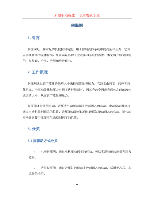
伺服阀1. 引言伺服阀是一种常见的机械控制装置,用于控制流体系统中的流量和压力。
它可以实现精确的流体控制,从而满足各种工业设备和系统的需求。
本文将介绍伺服阀的工作原理、分类、应用和维护保养。
2. 工作原理伺服阀通过调节流体的通道大小来控制流量和压力。
它通常由阀芯、阀座和阀体组成。
当驱动器施加压力对阀芯进行控制时,阀芯会改变阀座和阀体之间的流体通道的大小,从而调节流量和压力。
伺服阀通常采用电动、液压或气动驱动器来控制阀芯的移动。
电动驱动器可以通过电动机控制阀芯的位置,液压驱动器可以通过液压缸驱动阀芯的移动,而气动驱动器则使用压缩空气来控制阀芯的位置。
3. 分类3.1 按驱动方式分类•电动伺服阀:通过电机驱动阀芯的移动,可以实现精确的流量和压力控制。
•液压伺服阀:通过液压缸的驱动来控制阀芯的移动,适用于高压、高流量的应用。
•气动伺服阀:使用压缩空气作为动力源,驱动阀芯的移动,广泛应用于气动系统中。
3.2 按控制模式分类•恒定流量伺服阀:可以调节流体的通道大小,使其流量保持恒定。
•恒压伺服阀:可以调节流体的通道大小,使其压力保持恒定。
•比例控制伺服阀:根据输入信号的大小,通过调节流体的通道大小,实现流量和压力的比例控制。
3.3 按工作原理分类•阀式伺服阀:通过阀芯和阀座的开关控制来实现流量和压力的调节。
•调压器式伺服阀:通过调压器来调节流体的压力,从而实现流量和压力的控制。
4. 应用伺服阀在各个工业领域中都有广泛的应用,包括但不限于以下几个方面:1.液压系统:伺服阀可以用于控制液压系统中的液压马达和液压缸的流量和压力,以实现精确的运动控制。
2.机床:伺服阀可用于控制机床中的液压刀架和切割工具的运动,实现高精度的切割操作。
3.汽车工业:伺服阀常用于汽车的转向系统中,以实现对转向轮的精确控制。
4.能源领域:伺服阀可以用于控制石油、天然气和水电等能源的输送和分配,确保能源系统的安全和稳定运行。
5. 维护保养为了保证伺服阀的正常工作和延长使用寿命,以下是一些常见的维护保养措施:•定期检查:定期检查伺服阀的工作状态,包括阀芯和阀座的磨损情况,以及阀体和密封件是否有漏油等现象。

世界9大液压配件品牌世界液压配件品牌第1:派克(PARKER)派克汉尼汾公司是一家总部位于美国俄亥俄州的世界一流的工业企业,主要制造流体传动元器件及系统,用于控制各种机械和其他设备的传动、流量和压力。
派克提供1,400多条产品线,用于1,000多种工程机械、工业和航空航天领域内的项目。
派克是唯一一家能够给客户提供液压、气动、密封、机电一体化和计算机传动控制解决方案的制造商。
世界液压配件品牌第2:力士乐(Rexroth)(德国)博世力士乐生产先进的工业液压元件与系统,配合了微电子技术,令传动有力而精确。
其电子传动与控制产品及系统永远走在科技前端,为不同应用提供最佳的解决方案。
在线性传动与组装技术方面,力士乐把两种技术之优点融合,满足了客户不同的要求. 世界液压配件品牌第3:西德福(STAUFF)中国西德福是西德福国际公司独资在华建立的企业集团.西德福国际贸易(上海)有限公司是该企业集团的成员公司之一,在上海浦东外高桥保税区登记注册。
主要从事西德福国际公司的产品在中国国内市场上的推广与销售,为客户提供技术咨询和售后服务.世界液压配件品牌第4:贺德克(HYDAC)HYDAC贺德克德国HYDAC Technology GmbH 专业生产用于流体过滤技术、液压控制技术、电子测量技术的元件和装置,是世界著名的过滤器、蓄能器、液压阀、电子产品、管夹、电磁铁、液压系统总成等产品的液压件制造商。
HYDAC产品的应用范围十分广泛,几乎覆盖各行各业,尤其在冶金工业、汽车工业、电力设备、化工、工程机械、造纸工业、造船工业以及机床制造等领域都得到广泛应用. 世界液压配件品牌第5:阿托斯(Atos)Atos是世界领先的电液元件制造商,具有先进的技术能通过带电子器件的集成式液压无件提高现代化机器的性能。
世界液压配件品牌第6:爱力克(Aeroquip)Aeroquip爱力克 Aeroquip是伊顿集团流体动力部门旗下的一个全球知名的液压品牌,其主要产品包括液压软管及接头等。

威格士Vickers比例阀是一种常用于流体控制系统中的阀门,它能够根据输入信号的变化,精确地调节流体流量或压力。
以下是威格士Vickers比例阀的工作原理:
1. 结构:威格士Vickers比例阀由一个阀体和一个电磁控制芯片组成。
阀体内部有一个运动活塞(spool),它的位置可以通过电磁控制芯片的控制而改变。
2. 电磁控制:威格士Vickers比例阀的电磁控制芯片根据输入的电信号来控制活塞的位置。
电磁控制芯片由外部电源供电,通过调节电压和电流来控制芯片内部的线圈,从而产生电磁力。
3. 活塞运动:根据电磁力的作用,活塞会在阀体内部运动。
活塞的运动会改变阀体内部通道的开度,从而控制流体的流量或压力。
4. 反馈机制:威格士Vickers比例阀通常配备了反馈传感器,用于检测流体的实际流量或压力情况,并将反馈信号传回电磁控制芯片。
通过与输入信号进行比较,电磁控制芯片可以根据反馈信号动态调整活塞的位置,以保持设定的流量或压力。
总结来说,威格士Vickers比例阀的工作原理是通过电磁控制芯片控制活塞的位置,进而改变阀体内部通道的开度,从而实现对流体流量或压力的精确调节。
反馈机制可以帮助实时监测和调整阀门的工作状态,以满足实际应用的需求。

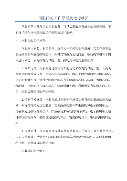
伺服阀的工作原理及运行维护伺服阀是一种常用的控制装置,可以实现液压系统中的精确控制。
下面将详细介绍伺服阀的工作原理及运行维护。
一、伺服阀的工作原理:伺服阀由阀芯、驱动部件、反馈元件和控制部件组成,其工作原理是利用控制部件感受控制信号,并将其转换为运动能量,驱动阀芯相对于阀体进行移动,从而改变阀口的开度,控制流体的流量或压力。
1.阀芯运动:伺服阀通过控制阀芯的运动来改变阀口的开度,从而调节流体的流量或压力。
当阀芯向右移动时,阀芯上的控制油腔与阀芯阀芯之间的通道连接,通过控制油腔的压力来驱动阀芯向右移动;当阀芯向左移动时,控制油腔与阀芯阀芯之间的通道关闭,利用弹簧力将阀芯向左移动,从而实现阀口的开闭控制。
2.控制信号感受:伺服阀通过控制部件感受到来自控制系统的压力信号,并将其转换为运动能量。
常见的控制部件有电磁铁和电子控制单元。
电磁铁通过接收电流信号,产生磁场来驱动阀芯的移动。
电子控制单元通过接收控制指令,根据设定的控制算法,输出控制信号,驱动伺服阀的运动。
3.反馈元件:伺服阀通过反馈元件来感知阀口的开度,如位移传感器、压力传感器等。
反馈元件将阀口的实际状态反馈给控制部件,从而实现闭环控制,确保阀口的准确控制。
二、伺服阀的运行维护:1.定期检查:定期检查伺服阀的工作状态,特别是阀芯和密封件的磨损情况。
如发现磨损严重,应及时更换。
同时,还需检查阀体和管路是否存在泄漏,以免影响系统的正常运行。
2.清洗维护:定期清洗伺服阀,清除阀体内的杂质和沉积物。
在清洗过程中,应注意不要损坏阀芯和密封件,并使用适当的润滑剂进行保养。
3.调试校准:在更换伺服阀或进行系统维护后,应进行调试和校准工作。
调试过程中,需要根据实际需求来控制阀芯的移动,保证阀口的准确控制。
校准过程中,需要根据系统要求和厂家指导,对伺服阀的参数进行调整和校准,以确保系统的正常运行。
4.注意环境影响:伺服阀的工作环境应尽量避免腐蚀性介质、高温和高湿等情况。

Vickers美国伊顿-威格士-油泵作用Vickers伊顿威格士油泵是一种既轻便又紧凑的泵,提出了一种具有一个由含铝材料制成的外壳的油泵和设置在该外壳中的可运动的模制件,其中,该可运动的模制件至少部分地由一种可烧结的、至少包含一种奥氏体的铁基合金的材料制成,并且其中由一种可烧结材料制成的该模制件具有一个至少为该外壳的热膨胀系数60%的热膨胀系数。
一、Vickers伊顿威格士-油泵作用1.提高油压(定压):将喷油压力提高到10MPa~20MPa。
2.控制喷油时间(定时):按规定的时间喷油和停止喷油。
3.控制喷油量(定量):根据柴油机的工作情况,改变喷油量的多少,以调节柴油机的转速和功率。
二、Vickers伊顿威格士-喷油泵对喷油泵的要求1.按柴油机工作顺序供油,而且各缸供油量均匀。
2.各缸供油提前角要相同。
3.各缸供油延续时间要相等。
4.油压的建立和供油的停止都必须迅速,以防止滴漏现象的发生。
三、Vickers伊顿威格士喷油泵的分类1.柱塞式喷油泵。
2.泵—喷油器式,将喷油泵和喷油器结合在一起。
3.转子分配式喷油泵。
Vickers伊顿威格士喷油泵喷油泵是汽车柴油机上的一个重要组成部分。
喷油泵总成通常是由喷油泵、调速器等部件安装在一起组成的一个整体。
其中调速器是保障柴油机的低速运转和对最高转速的限制,确保喷射量与转速之间保持一定关系的部件。
而喷油泵则是柴油机最重要的部件,被视为柴油发动机的“心脏”部件,它一旦出问题会使整个柴油机工作失常。
Vickers伊顿威格士喷油泵的工作原理它的基本工作原理就是在泵里面有两组对置柱塞安装在叶轮上,叶轮被发动机带动转动时,柱塞也随之转动,由于凸轮环的凸起部分压动柱塞,使柱塞发挥象泵的作用一样向叶轮中央的送油孔压送柴油,这时送出去的柴油充满了分配器入口处,然后按各汽缸顺序排列喷射。
1、Vickers伊顿威格士吸油和压油过程喷油泵的吸油和压油,由柱塞在柱塞套内的往复运动来完成。

006Table of ContentsEXPLODED VIEW DRAWINGS . . . . . . . . . . . . . . . . . . . . . . . . . . . . . . . . . . . . . . . . . . . . . . . . . . . . . . . . . . . . . . .3 TOOLS REQUIRED FOR DISASSEMBL Y &REASSEMBL Y . . . . . . . . . . . . . . . . . . . . . . . . . . . . . . . . . . . . . . . . . . . . . . . . . . . . . . . . . . . . . . . . . . . . . . . . . . . . .4 DISASSEMBL Y . . . . . . . . . . . . . . . . . . . . . . . . . . . . . . . . . . . . . . . . . . . . . . . . . . . . . . . . . . . . . . . . . . . . . . . . . . . .5 REASSEMBL Y . . . . . . . . . . . . . . . . . . . . . . . . . . . . . . . . . . . . . . . . . . . . . . . . . . . . . . . . . . . . . . . . . . . . . . . . . . . . .7 WHEEL MOTOR . . . . . . . . . . . . . . . . . . . . . . . . . . . . . . . . . . . . . . . . . . . . . . . . . . . . . . . . . . . . . . . . . . . . . . . . . . .9 STANDARD/WHEEL MOTOR WITH SEAL GUARD . . . . . . . . . . . . . . . . . . . . . . . . . . . . . . . . . . . . . . . . . . . . . . .9 STANDARD/WHEEL MOTOR WITH EXTREMEDUTY SEAL GUARD . . . . . . . . . . . . . . . . . . . . . . . . . . . . . . . . . . . . . . . . . . . . . . . . . . . . . . . . . . . . . . . . . . . . . .10 BEARINGLESS MOTOR . . . . . . . . . . . . . . . . . . . . . . . . . . . . . . . . . . . . . . . . . . . . . . . . . . . . . . . . . . . . . . . . . . . .10 DISASSEMBL Y — REASSEMBL YSHUTTLE VAL VE OPTION . . . . . . . . . . . . . . . . . . . . . . . . . . . . . . . . . . . . . . . . . . . . . . . . . . . . . . . . . . . . . . . . . .10 REASSEMBL Y — SPEED SENSOR . . . . . . . . . . . . . . . . . . . . . . . . . . . . . . . . . . . . . . . . . . . . . . . . . . . . . . . . . . .11 PRODUCT IDENTIFICATION . . . . . . . . . . . . . . . . . . . . . . . . . . . . . . . . . . . . . . . . . . . . . . . . . . . . . . . . . . . . . . . .12 PARTS NUMBERS & EXPLODED VIEWS . . . . . . . . . . . . . . . . . . . . . . . . . . . . . . . . . . . . . . . . . . . . . . . . . . . . . .1322000 SerieS diSc val ve geroler motor C-MOLO-TM010-E2 May 2019 32000 Series Disc Valve Motors2000 SerieS diSc valve geroler motor C-MOLO-TM010-E2May 2019 Valve face sealValve 2000 Series Disc valve motor exploded viewExploded view applicable for displacement codes 021, 025 and 04042000 Series Disc Valve Motors2000 SerieS diSc val ve geroler motor 2 C-MOLO-TM010-E2 May 2019 Tools required for disassembly and reassembly.Torque wrench 57Nm [500 lb-in] capacity 300-450 [12-16]* breaker bar 9/16 socketSmall screwdriver 150-200 x 6,5 [6-8 x 1/4] blade 3/16 Allen wrench Press* Unless indicated otherwise, measurements are given in mm [inches]** Shaft seal installation tool (600496)** Bullet (600465) for 1 diameter shaftsThe following tools are not necessary for disassembly and reassembly, but areextremely helpful. Alignment studs (2)8,0 [.312]Grind at spots on each sideAlignment studs (2)52000 Series Disc Valve Motors2000 SerieS diSc valve geroler motor C-MOLO-TM010-E2 May 2019 DisassemblyCleanliness is extremely important when repairing ahydraulic motor. Work in a clean area. Before disconnecting the lines, clean the port area of the motor thoroughly. Use a wire brush to remove foreign material and debris from around the exterior joints of the motor. Check the shaft and key slot, remove all nicks, burrs or sharp edges that might damage the bearing housing seals when installing the shaft and bearing assembly. Before starting the disassembly procedures, drain the oil from inside the motor.1. Place the motor in a vise with the output shaft down.Clamp across the mounting flange of the motor not the housing. Excessive clamping pressure will cause distortion. When clamping, use some protective device on the vise, such as special soft jaws, pieces of hard rubber or board.Although not all drawings show the motor in a vise, we recommend that you keep the motor in the vise during disassembly and reassembly. Follow the clamping procedures explained throughout the manualTie Bolts2. Remove 4 bolts from motor.3. Lift valve housing straight up. If done carefully thepins, springs, balance ring assembly, and valve will4. Carefully remove 79,1 [3.11] diameter seal fromvalve housing.5. Remove case drain plug—with seal, fromvalve housing.6. Remove 2 pins and 2 springs from balance ringassembly, see Figure 5.Outer Face SealInner Face SealPin (2) and Spring (2)Valve Balance Ring7. Remove balance ring assembly.8. Remove inner and outer face seals frombalance ring.9. Remove the valve.Figure 1.Figure 2.Figure 3.Figure 4.Figure 5.62000 Series Disc Valve Motors2000 SerieS diSc val ve geroler motor 2 C-MOLO-TM010-E2 May 2019 Seal Valve DriveValve Plate10. (A) Remove the valve plate.11. (A) Remove the 79,1 [3.11] diameter seal fromvalve plate.12. (A) Remove the valve drive.SealDrive RetainerGerolerValve PlateValve DriveRetaining Ring10. (B) Remove the Valve Drive and Retaining Ring11. (B) Remove valve plate and 79,1 [3.11] diameter sealfrom valve plate12. (B) Remove drive retainer13. Remove the Geroler. Be sure to retain the rollers inthe outer ring if they are loose.14. Remove the drive.15. Remove the 79,1 [3.11] diameter seal fromwear plate, see Figure 7.16. Remove the wear plate.17. Remove the shaft face seal from the wear plate.18. Remove the 78,0 [3.07] diameter seal frombearing housing.Bearing HousingShaft and Bearing Assembly19. You may need a press to remove shaft and bearingassembly from bearing housing. (Key must be removed before removing shaft.)Bearing Housing Shaft SealBack-up WasherExclusion Seal20. Use a small screwdriver to remove shaft seal,back-up washer and exclusion seal from bearing housing, see Figure 10. Do not damage bore of housing.Noee:N Individual parts of shaft and bearing assembly are notsold separately. Replace as a unit.DisassemblyFigure 6 (A) .Figure 6 (B) . A pplicable for displacement codes021, 025 and 040Figure 7 .Figure 8 .Figure 9 .Figure 10 .72000 Series Disc Valve Motors2000 SerieS diSc valve geroler motor C-MOLO-TM010-E2 May 2019 Check all mating surfaces. Replace any parts that havescratches or burrs that could cause leakage. Clean all metal parts in clean solvent. Blow dry with air. Do not wipe dry with cloth or paper towel because lint or other matter can get in the hydraulic system and cause damage. Do not use a coarse grit or try to file or grind these parts. Check around the keyway and chamfered area of the shaft for burrs, nicks or sharp edges that can damage the seals when reassem-bling the bearing housing.Noee:N Use new seals when reassembling this motor. Referto parts list (6-129) for proper seal kit number.21. Use a press to install exclusion seal in outer bore ofbearing housing. Lip of seal must face outward. See Figure 11. If a press is not available use a plastic or rubber hammer, being careful not to damage or cock seal in the bore.Seal22. Place back-up washer into seal bore. Place shaft sealonto installation tool (600496) and press seal into seal bore of the housing.23. Clamp housing in vise, see Figure 1.24. Place protective bullet (see note below) over shaft.Apply petroleum jelly to inside diameter of dust and shaft seal. You may need a press to install shaft and bearing assembly. Do not distort shaft seal. Damage to this seal will cause leakage.Noee:N Note: Bullet (600465), for 1inch dia. shafts,available — by special order. Use tape over other shafts to prevent cutting the seals.25. Install the red colored 78,0 [3.07] diameter seal intothe bearing housing with flat side down.26. Alignment studs can be very helpful in reassemblyof the motor. See special tool listing page 2. If you use studs, install 2 studs diagonally opposed in the bearing housing.27. Install the shaft face seal in the wear plate as shownin Figure 11. Do not distort seal.28. Install the wear plate, see Figure 11.29. Install the 79,1 [3.11] diameter seal in the wear platewith flat side down.30. Install the drive into the output shaft.31. Align the notch on the outside of the Geroler with thenotch on the wear plate. Install the Geroler against the wear plate. Be sure to retain the rollers in the outer ring if they are loose.32. Install the valve drive in the Geroler.Noee:N Installation at this time involves 3 steps in the timingof the motor. Timing determines the direction of rota-tion of the output shaft.Timing parts include:1. Geroler 2. Valve Drive 3. Valve Plate4. ValveOpen PocketRef. OnlyTiming Soep # 1 — Locate the largest open pocket in the Geroler and mark it on the outside edge of the Geroler.33. Install the 79,1 [3.11] diameter seal in groove ofvalve plate with flat side down.ReassemblyFigure 11 .Figure 12 . Timing alignmeno82000 Series Disc Valve Motors2000 SerieS diSc val ve geroler motor 2 C-MOLO-TM010-E2 May 2019 34. Align the notch on the outside of the valve plate withthe notch on the Geroler as shown in Figure 12.Timing Soep # 2 — Locate the slot opening in the valve plate which is in line with the largest open pocket of the Geroler.Timing Soep # 3 — Locate any one of the side openings of the valve and align this opening with the open slot of the valve plate that is in line with the largest open pocket of the Geroler. Install the valve by rotating it clockwise until the spine teeth engage (1/2 spine tooth max.). This will provide the proper rotation when pressurized as shown in Figure 13.Rotation CounterRotationValve Housing35. Install 2 springs and 2 pins in the holes located in thebore of the valve housing, as shown in Figure 14.36. Install the 79,1 [3.11] diameter seal in the valvehousing with flat side down.37. Apply petroleum jelly to inner and outer face seals.Install seals on balance ring as shown in Figure 15.ImpNroano : Install face seals in the positions shown in Figure 15, or the motor will not operate properly. Do not force or bend the face seals. Any damage to these seals willaffect the operation of the motor.Balance Ring38. Align pin notches in balance ring with pins in bore ofvalve housing. Install balance ring assembly in valve housing.StudsRingValve Valve Plate39. Insert your finger through port of valve housing.Apply pressure to side of balance ring as shown in Figure 16. Hold ring in position until valve housing is in place against valve plate (see Figure 17).Noee:N After installing the valve housing on the valve platecheck for proper placement. Push down on the valve housing. Y ou should get a slight spring action.get a slight spring action.ReassemblyFigure 16 .Figure 13.Figure 14.Figure 15 .Figure 17 .92000 Series Disc Valve Motors2000 SerieS diSc valve geroler motor C-MOLO-TM010-E2 May 2019 40. Install tie bolts. If you use alignment Studs, install2 bolts opposite the studs. Finger tighten the bolts. Remove the alignment studs and replace with the two remaining bolts. Torque all four bolts alternately to 50 Nm [450 lb-in].41. Install seal on case drain plug then install in valvehousing. Torque to 6 Nm [50 lb-in.]On wheel motors, a different bearing housing is used, see Figure 19. Other than this the parts are the same as the standard motor and the same disassembly and reassembly procedures apply.Standard/Wheel motor with seal guardInstallation of seal guard:After completing assembly of the shaft and bearingassembly into the bearing housing, press the seal guard onto the shaft with a tool that will provide an even push over the seal. This tool must bottom out against the bearing housing and provide a 4,5 mm [.177 inch] stop for the seal guard. Applicable for standard and wheel mount motors.Seal GuardReassemblyWheel motorFigure 19 .Figure 18 .Figure 20 .102000 Series Disc Valve Motors2000 SerieS diSc val ve geroler motor 2 C-MOLO-TM010-E2 May 2019 Standard/Wheel motor with extreme duty seal guardInstallation of extreme duty seal guard:After completing assembly of the shaft and bearingassembly into the bearing housing, press the Extreme Duty Seal Guard onto the shaft with a tool that will provide an even push over the seal. This tool must bottom out against the bearing housing and provide a 7,1 mm [.28 inch] stop for the seal guard. (Applicable for standard and wheelmount motors)Extreme Duty Seal guardBearing Housing with Extreme Duty Seal guard GrooveThis motor is the same as the standard motor without the shaft/bearing assembly, and bearing housing. The mounting flange replaces the bearing housing, see Figure 22. Follow same disassembly and reassembly procedures as rear section of standard motor.Bearingless motorDisassembly reassembly shuttle valve optionDisassembly of shuttle valve option, this valve is located in the valve housing. Clean and inspect shuttle valve parts and reassemble with new seals, torque plugs to8-11 Nm [75-100 lb-in].Shuttle Locationwhen ApplicableFigure 21 .Figure 22 .Figure 23 .2000 Series Disc Valve Motors Reassembly — Speed sensor1. Rotate the motor shaft until a (gear/target) tooth is centered in the speedsensor port. If this is not done, thesensor may be damaged during theoperation of the motor.2. Make sure the lock nut and its threadsare clean and dry for the propertorque. Position the lock nut againstthe alignment nut as shown in Figure24.3. Move the washer and the o-ringup against the speed sensor bodythreads as shown in Figure 24.4. By hand, lightly thread the speedsensor body into the housing untilthe sensor touches against the motor(gear/target) tooth.Do not force the sensor against the(gear/target) tooth, damage mayoccur. Make sure the o-ring or thewasher do not touch the housing —see Figure 25.5. Turn the speed sensor body out onequarter turn (CCW) plus the additionalamount (CCW) needed to make thealignment notches perpendicular tothe motor shaft centerline (90° +/-5degrees from the motor shaft center-line — Figure 26 and 27).6. Maintain the speed sensor bodyalignment (Figure 27), and tightenthe lock nut to 8,5-14 Nm [75-125lb-in.] (torque values are for clean drythreads).7. Check the speed sensor body forcorrect alignment (Figure 27), reinstall the sensor if it is not correct.Speed Sensor BodyFigure 24 .Figure 25 .Figure 26 .Figure 27 .Alignment NutLock NutHousingGear/TargetToothWasherO-ring2000 Series Disc Valve MotorsUse digit pre x —104-, 105-, or 106- plus four digit number from chartsfor complete product number—Example 106-1039.Product Numbers—2000 SeriesEach Order Must Include the Following:How to Order Replacement Parts 1. Product Number 2. Date Code 3. Part Name4. Part Number5. Quantity of PartsFor Additional Literature Contact Eaton Corp. Hydraulics Division 15151 Highway 5 Eden Prairie, MN 55344.Speci cations and performance data, Catalog No. 11-878Replacement part numbers and kit information — Parts Information No. 6-129Product Line Identi cation NumberProductIdenti cation NumberEngineering Change CodemoUNtiNg SHaFtPort SiZediSPl. cm3/ r [in3/ r]/ ProdUct NUmBer41* [2.5]80[4.9]100[6.2]130[8.0]160[9.6]195[11.9]245[14.9]305[18.7]395[24.0]490[29.8]2 Bolt SAE A Flange1 Inch Straight7/8 -14 O-ringStaggered 104-4708-1001-1002-1003-1004-1005-1006-1007-1143—1 1/16 -12 O-ring 180° Apart 104-–––-1037-1038-1039-1040-1041-1042-1043-1044—1 1/4 Inch Straight7/8 -14 O-ring Staggered 104-4774-1022-1023-1024-1025-1026-1027-1028-1228-14201 1/16 -12 O-ring 180° Apart 104-–––-1061-1062-1063-1064-1065-1066-1067-1068-14211 1/4Inch - 14 T Splined 7/8 -14 O-ring Staggered 104-4764-1029-1030-1031-1032-1033-1034-1035-1229-14221 1/16 -12 O-ring 180° Apart 104-–––-1087-1088-1089-1090-1091-1092-1093-1094-14232 Bolt SAE B Flange1 1/4 Inch Straight 7/8-14 O-ring Staggered 104-–––-1200-1201-1202-1203-1204-1205-1206-1207—1 1/4 Inch Involute SAE C Splined 7/8 -14 O-ring Staggered104-–––-1208-1209-1210-1211-1212-1213-1214-1215—1 Inch SAE 6B Splined 7/8 -14 O-ring Staggered 104-–––-1193-1194-1195-1196-1197-1198-1199——7/8 Inch SAE B Splined7/8 -14 O-ring Staggered 104-–––-1216-1217-1218-1219-1220————Standard with 4 Bolt Flange32 mm Straight G 1/2 (BSP))104-4672-1384-1385-1386-1387-1388-1389-1390-1391—1 1/4 Inch 14 T Splined G 1/2 (BSP)104-–––-1376-1377-1378-1379-1380-1381-1382-1383—Wheel Motor1 1/4 Inch Straight7/8 -14 O-ring Staggered 105-–––————————-11481 1/16 -12 O-ring 180° Apart 105-–––————————-114932 mm Straight G 1/2 (BSP)105-–––-1134-1135-1136-1137-1138-1139-1140-1141—1 1/4 Inch Tapered 7/8 -14 O-ring Staggered 105-–––-1001-1002-1003-1004-1005-1006-1007-1060-11521 1/16 -12 O-ring 180° Apart 105-–––-1071-1072-1073-1074-1075-1076-1077-1078—1 1/4 Inch 14 T Splined7/8 -14 O-ring Staggered 105-–––-1029-1030-1031-1032-1033-1034-1035-1096—1 1/16 -12 O-ring 180° Apart 105-–––-1079-1080-1081-1082-1083-1084-1085-1086—Bearingless7/8 -14 O-ring Staggered 106-–––-1008-1009-1010-1011-1012-1013-1014-1015-1047G 1/2 (BSP)106-–––-1038-1039-1040-1041-1042-1043-1044-1045—*New Release104-1007Product identification2000 Series Disc Valve Motorsdisplacement cm 3/r [in 3/r]drive, mainitem No. 9 —Part No./length mm [inch]21371-009 76,2 [3.00]geroler ®item No. 10 —Part No./Width mm [inch]21625-00117,8 [ .70]21371-010 80,8 [3.18]22,5 [ .88]21371-004 87,2 [3.43]28,9 [1.14]21371-004 87,2 [3.43]28,9 [1.14]21371-005 94,0 [3.70]35,6 [1.40]21371-006103,1 [4.06]44,7 [1.76] 80 [ 4.9]100 [ 6.2]130 [ 8.0]160 [ 9.6]195 [11.9]245 [14.9]305 [18.7]21371-007114,4 [4.51]56,0 [2.21]mm [in.]14384-004126.7 [4.99]mm [in.]108,2 [4.26]135,4 [5.33]113,0 [4.45]138,4 [5.45]121,1 [4.77]138,4 [5.45]121,1 [4.77]144,8 [5.70]126.7 [4.99]154,9 [6.10]138,4 [5.45]164,5 [6.48]144,8 [5.70]Part No.Screw, cap (Bearingless)item No. 21 —Part No./length Screw, cap (Standard/Wheel)item No. 21 —Part No./length Part No.21625-00221625-00321625-00421625-00521625-00621625-00714384-00614384-00714384-00714384-00814384-01014384-01214384-00121371-023 80.4 [3.17]21625-01714.7 [ .58] 66 [ 4.0] 14384-004126.7 [4.99] ---------- ----------21371-022 75.7 [2.98]21625-0169.0 [ .36]41 [ 2.5] 14384-003121.2 [4.77] ---------- ----------21371-024 74.2 [2.92]21625-0207.5 [ .30] 34 [ 2.1] 14384-033117.3 [4.62] ---------- ----------14384-00214384-00314384-00314384-00414384-00714384-008Part No.Part No.21371-008130,4 [5.13]72,0 [2.83]395 [24.0]490 [29.8]21371-012147,9 [5.82]89,4 [3.52]182,4 [7.18]164,5 [6.48]199,6 [7.86]182,4 [7.18]21625-00821625-01014384-01414384-01914384-01214384-0142000 Series Disc Valve MotorsValve1131121466-000Valve — Speed Sensor Valve 111201307-002Balance Ring 1118915-000Housing, Valve (G 1/2 (BSP) Ports — G 1/4 (BSP) Case Drain Port)2O†Seal3335998675-001121Drive, Valve 118433-000111Plate, Valve 1122134-000117O†Seal, Face, Inner 119049-00118O†1Seal, Face, Outer119135-002162Spring, Compression 227383-000Housing, Valve (7/8-14 Str. Thrd. O-ring Ports — 7/16-20 Case Drain Port)1191111Seal, Shaft 116043475-0014†Seal, Exclusion 119121-0013†Housing, Valve (1 - 1/16-12 180 Apart — 7/16-20 Case Drain Port)11111101Geroler ®11*9Drive, Main 111*21564-00721564-00121564-00214Housing, Valve (7/8-14 Str. Thrd. O-ring Ports — 7/16-20 Case Drain Port) — Shuttle Valve Housing 11121564-010Housing, Valve (1 - 1/16-12 180 Apart — 7/16-20 Case Drain Port) — Speed Sensor Housing 121564-016Housing, Valve (7/8-14 Str. Thrd. O-ring Ports — 7/16-20 Case Drain Port) — Speed Sensor Housing 121564-012111Housing, Valve (G 1/2 (BSP) Ports — G 1/4 (BSP) Case Drain Port) — Speed Sensor Housing 21564-015111Item No.DescriptionBrgl.Whl.Std.Quantity per UnitPartNumberShaft and Bearing Kit (1-1/4 in. Splined 14T)1121618-004Shaft and Bearing Kit (1-1/4 in. Tapered)1121618-003Shaft and Bearing Kit (1-1/4 in. Tapered — Special shaft for Seal Guard 121618-032 Nut, Hex (1-1/4 in. Tapered Shaft)1114163-000 Key (for 1-1/4 in. Tapered Shaft)1114392-0061Shaft and Bearing Kit (7/8 Splined 13T)121618-0071Shaft and Bearing Kit (1 inch Straight)1121618-001 Key (for 1 Straight Shaft)1114193-000Shaft and Bearing Kit (1-1/4 inch Straight)1121618-002 Key (for 1-1/4 Straight Shaft)1114392-008Shaft and Bearing Kit (1 in. 6B Splined)1121618-005111Shaft and Bearing Kit (25 mm Straight)121618-026 Key (for 25 mm Straight Shaft)14462-006111Shaft and Bearing Kit (32 mm Straight)121618-023 Key (for 32 mm Straight Shaft)14460-005Pin, Balance Ring 22214351-00015Housing, Valve (Manifold Mount — 7/16-20 Case Drain Port)11121564-004Housing, Valve (Manifold Mount — G 1/4 (BSP) Case Drain Port)11121564-0085†Ring, Back-up1117382-000Housing, Bearing, Wheel Mount (Four Bolt)1121578-003Housing, Bearing, Wheel Mount (Four Bolt) — Compatible for HAYES Brake 121578-015Housing, Bearing, SAE A (Two Bolt) 121578-0046Housing, Bearing, SAE B (Two Bolt) 121578-001Housing, Bearing, Diagonal (Four Bolt)121578-005Housing, Bearing, Magneto (Four Bolt)121578-008Housing, Bearing, Wheel Mount (Four Bolt) — with Seal Guard Groove 21578-016Seal, Shaft Face 119050-0007†Plate, Wear 1122102-0008Continued on Page 16Housing, Valve (7/8-14 Str. Thrd. O-ring End Ports — 7/16-20 Case Drain Port)11121564-0062000 Series Disc Valve Motorsdisplacement cm 3/r [in 3/r]drive, mainitem No. 9 —Part No./length mm [inch]21371-009 76,2 [3.00]geroler ®item No. 10 —Part No./Width mm [inch]21625-00117,8 [ .70]21371-010 80,8 [3.18]22,5 [ .88]21371-004 87,2 [3.43]28,9 [1.14]21371-004 87,2 [3.43]28,9 [1.14]21371-005 94,0 [3.70]35,6 [1.40]21371-006103,1 [4.06]44,7 [1.76] 80 [ 4.9]100 [ 6.2]130 [ 8.0]160 [ 9.6]195 [11.9]245 [14.9]305 [18.7]21371-007114,4 [4.51]56,0 [2.21]mm [in.]14384-004126.7 [4.99]mm [in.]108,2 [4.26]135,4 [5.33]113,0 [4.45]138,4 [5.45]121,1 [4.77]138,4 [5.45]121,1 [4.77]144,8 [5.70]126.7 [4.99]154,9 [6.10]138,4 [5.45]164,5 [6.48]144,8 [5.70]Part No.Screw, cap (Bearingless)item No. 21 —Part No./length Screw, cap (Standard/Wheel)item No. 21 —Part No./length Part No.21625-00221625-00321625-00421625-00521625-00621625-00714384-00614384-00714384-00714384-00814384-01014384-01214384-00121371-023 80.4 [3.17]21625-01714.7 [ .58] 66 [ 4.0] 14384-004126.7 [4.99] ---------- ----------21371-022 75.7 [2.98]21625-0169.0 [ .36]41 [ 2.5] 14384-003121.2 [4.77] ---------- ----------21371-024 74.2 [2.92]21625-0207.5 [ .30] 34 [ 2.1] 14384-033117.3 [4.62] ---------- ----------14384-00214384-00314384-00314384-00414384-00714384-008Part No.Part No.21371-008130,4 [5.13]72,0 [2.83]395 [24.0]490 [29.8]21371-012147,9 [5.82]89,4 [3.52]182,4 [7.18]164,5 [6.48]199,6 [7.86]182,4 [7.18]21625-00821625-01014384-01414384-01914384-01214384-014Exploded view applicable for displacement codes 021, 025 and 040item No.descriptionBrgl.Whl.Std.Quantity per UnitPartNumbercontinued from Page 14Seal1 O 2915127-000272Sleeve, Dash Pot228755-000228Plug Assembly (9/16-18 Shuttle Valve End)229072-0052O-ring 2121111250003-906Seal Kit (Std. and Whl. Motors)—Contains Parts Indicated by †* —See Chart on Opposite Page.61258-00061259-00061263-00061261-000Seal Kit,Viton**(Bearingless Motor Only)—Contains Parts Indicated by O** —Viton Seal Part Numbers Differ from Part Numbers Shown above. Note: Backup Ring Item 5 is not used with Viton Shaft Seal Item 4.Seal Kit, Viton**(Std. and Whl. Motors)—Contains Parts Indicated by †Viton® is a Registered Trade Name of Dupont Corporation.Seal, Flange, Mounting13021569-000Guard, Seal 4114628-00261289-000Seal Kit, Wheel Motor with Seal Guard—Contains Parts Indicated by † and Seal Guard (Item No. 41)262Spring22230079-000Poppet 225228567-000Sensor, Speed — 127mm [5.0 in.] Lead Wire 391201137-001111Ring, Retaining 69114829-001Seal705996787-002Retainer, Drive 6816035860-001Screw, Cap 44421*241Piston Shuttle 118566-0001Plug Assembly (G 1/4 (BSP) Case Drain Plug)119170-0021O-ring11250003-904O††Plug Assembly (7/16-20 Case Drain Plug)1119072-00320O† O-ring111250003-904Seal Kit (Bearingless Motor Only)—Contains Parts Indicated by ONotes:EaoNn1000 Eaton Boulevard Cleveland, OH 44122 United States © 2019 EatonAll Rights Reserved Printed in USA Eaton is a registered trademark.EaoNnHydraulics Group USA 14615 Lone Oak Road Eden Prairie, MN 55344 USATel: 952-937-9800Fax: 952-294-7722 /hydraulics EaoNnHydraulics Group EuropeRoute de la Longeraie 71110 MorgesSwitzerlandTel: +41 (0) 21 811 4600Fax: +41 (0) 21 811 4601EaoNnHydraulics Group Asia PacificEaton BuildingNo.7 Lane 280 Linhong RoadChangning District,Shanghai 200335ChinaTel: (+86 21) 5200 0099Fax: (+86 21) 2230 7240。
美国MOOG伺服阀,伺服阀的工作原理及作用1、电液伺服阀主要用于电液伺服自动控制系统,其作用是将小功率的电信号转换为大功率的液压输出,经过液压执行机构来完成机械设备的自动化控制.伺服阀是一种经过改动输入信号。
依据输入信号的方式不同,分为电液伺服阀和机液伺服阀。
电液伺服阀既是电液转换元件,又是功率放大元件,它的作用是将小功率的电信号输入转换为大功率的液压能(压力和流量)输出,完成执行元件的位移、速度、加速度及力控制。
液压泵的输出压力是指液压泵在实践工作时输出油液的压力,即泵工作时的出口压力,通常称为工作压力,其大小取决于负载。
电液伺服阀通常由电气—机械转换安装、液压放大器和反应(均衡)机构三局部组成。
反应战争衡机构使电液伺服阀输出的流量或压力取得与输入电信号成比例的特性。
压力的稳定通常采用压力控制阀,比方溢流阀等。
2.细致材料:典型电---气比例阀、伺服阀的工作原理电---气比例阀和伺服阀按其功用可分为压力式和流量式两种。
压力式比例/伺服阀将输给的电信号线性地转换为气体压力;流量式比例/伺服阀将输给的电信号转换为气体流量。
美国威格士VI CKERS柱塞泵由于气体的可紧缩性,使气缸或气马达等执行元件的运动速度不只取决于气体流量。
还取决于执行元件的负载大小。
因而准确地控制气体流量常常是不用要的。
单纯的压力式或流量式比例/伺服阀应用不多,常常是压力和流量分离在一同应用更为普遍。
电---气比例阀和伺服阀主要由电---机械转换器和气动放大器组成。
但随着近年来低价的电子集成电路和各种检测器件的大量呈现,在1电---气比例/伺服阀中越来越多地采用了电反应办法,这也大大进步了比例/伺服阀的性能。
电---气比例/伺服阀可采用的反应控制方式,阀内就增加了位移或压力检测器件,有的还集成有控制放大器。

VICKERS威格士液压阀维修注意事项资料 VICKERS威格士液压阀维修注意事项资料VICKERS威格士液压阀维修过程中,对VICKERS威格士液压阀进行拆卸清洗属于首道工序。
在液压设备实际使用过程中,由于液压油污染会导致油污沉淀,或者在液压油中存在的一些颗粒状杂质,这些均会导致VICKERS威格士液压阀出现故障,通常情况下在拆卸清洗之后便可将这些故障排除,使VICKERS威格士液压阀能够恢复其功能。
对于VICKERS威格士液压阀拆卸清洗而言,其主要包括以下五个方面内容:(1)拆卸。
对于VICKERS威格士液压阀而言,其各个零件之间虽然大多由螺栓进行连接,但是VICKERS威格士液压阀在进行设计时是非拆卸的,若缺乏专用设备或者缺乏专业技术而强行进行拆卸,其所可能导致的结果就是损坏VICKERS威格士液压阀。
所以,在拆卸之前维修人员应当将VICKERS威格士液压阀结构掌握,并且应当掌握各个零件之间连接方式,在拆卸过程中应当对不同零件之间位置关系进行记录。
(2)检查清理。
对阀体及阀芯等零件进行检查,观察其污垢沉积情况,在对工作表面不造成损伤的基础上,利用毛刷、棉纱以及非金属刮板将集中污垢清除。
(3)粗洗。
将阀芯与阀体在清洗箱托盘上放置,并对其进行加热浸泡,在清洗槽底部通人压缩空气,利用气泡产生的搅拌作用,将残存污物清洗掉,在条件允许情况下可行超声波清洗。
(4)精细。
先以清洗液进行高压定位清洗,然后以热风干燥。
在企业有条件情况下,可选择现有清新剂,在一些特殊场合也可以对有机清洗剂进行使用,比如汽油及柴油等。
(5)装配。
根据VICKERS威格士液压阀示意图或者在拆卸时所记录零件装配关系进行装配,在装配过程中应当注意小心操作,防止零件被损伤。
对于一些原有密封材料而言,在实际拆卸过程中很容易受到损坏,所以在装配时应当进行更换。
美国威格士溢流阀和顺序阀:CG2V6/8,10系列、CG5V6/8,20系列;CG2V***11; CG5V***D*VM***L*52*;美国VICKERS卸荷溢流阀:EURG1/206/10,13系列、EURT1/206/10,12系列,(F3)EUR*****(V)****; CGR02,21;F3CGR02*K21;美国威格士流量阀: FN,FCG,FRG,FN03/06/10系列、FC/FCG02系列、FC/FCG03系列、 FRG03系列;FN0320、FN8S0220,(F3)FCG02****LT5*S*,(F3)FCG0328美国VICKERS溢流阀:22S*;FN4,20系列;(F3)FN14K20;FCG3,10系列, FCG3***A*10;FN03系列、FN06系列、FN10系列;美国威格士方向阀: DG4V3S,EN490,型号:DG4V3S***L**VM********760EN490P**A**B**T**GD4V360系列、GD4V3S60系列、CVUA6PD, DG3/4VP3系列、GD4V3,DG4V3S系列VICKERS液压阀技术要求:1)动作灵活,作用可靠,工作时冲击和振动小,噪声小,使用寿命长。

VICKERS威格士叶片泵表面粘涂原理及特点美国VICKERS威格士叶片泵表面粘涂原理及特点我司威斯特(上海)仪器仪表有限公司专业销售美国VICKERS威格士叶片泵,大量库存、型号齐全、保证原装正品、价格有优势,欢迎经销商及终端客户前来询价。
VICKERS美国威格士是伊顿集团流体动力部门旗下的一个全球知名的液压品牌,其主要产品包括威格士伺服阀、威格士柱塞泵、威格士叶片泵、威格士液压泵、威格士马达、油缸、威格士液压阀等。
伊顿的流体动力产品应用广泛,包括土方机械、农业、建筑、航空、采矿、林业、公共设施和物料搬运。
伊顿是全球*的多元化工业产品制造商,在全球的工业领域享有技术先进、质量可靠的声誉。
在全球6大洲超过125个国家拥有5万5千名员工。
年销售额为98亿美元。
产品涉及汽车、卡车、重型设备、民航、居住、电讯和数据传输、工业设备和公共设施、商业机构和政府机关、以及运动和娱乐的各个领域。
一、美国VICKERS威格士叶片泵表面粘涂原理及特点1、近年来表面粘涂技术我国设备维修得到了广泛应用,适用于各种材质零件设备修补。
其工作原理将加入二硫化钼、金属粉末、陶瓷粉末纤维等特殊填料胶粘剂,直接涂敷于材料或零件表面,使之具有耐磨、耐蚀等功能,主要用于表面强化修复。
它工艺简单、方便灵活、安全可靠,不需要专门设备,只需将配好胶涂敷于清理好零件表面,待固化后进行修整即可,常室温下操作,不会使零件产生热功当量影响变形等。
二、粘涂层涂敷工艺1、轴套外圆、轴套端面贴合面、齿轮端面或泵壳内孔小面积均匀性磨损量0.15-0.50mm之间、划痕深度0.2mm以上时,宜采用粘涂修补工艺。
粘涂层涂敷工艺过程:初清洗→预加工→最后清洗及活化处理→配制修补剂→涂敷→固化→修整、清理或后加工。
2、粘涂工艺虽然比较简单,但实际施工要求却相当严格,仅凭选择好胶粘剂,不一定能获得高粘涂强度。

Enterprise Development专业品质权威Analysis Report企业发展分析报告伊顿威格士液压(上海)有限公司办事处免责声明:本报告通过对该企业公开数据进行分析生成,并不完全代表我方对该企业的意见,如有错误请及时联系;本报告出于对企业发展研究目的产生,仅供参考,在任何情况下,使用本报告所引起的一切后果,我方不承担任何责任:本报告不得用于一切商业用途,如需引用或合作,请与我方联系:伊顿威格士液压(上海)有限公司办事处1企业发展分析结果1.1 企业发展指数得分企业发展指数得分伊顿威格士液压(上海)有限公司办事处综合得分说明:企业发展指数根据企业规模、企业创新、企业风险、企业活力四个维度对企业发展情况进行评价。
该企业的综合评价得分需要您得到该公司授权后,我们将协助您分析给出。
1.2 企业画像类别内容行业通用设备制造业-其他通用设备制造业资质空产品服务围内的业务联络。
1.3 发展历程2工商2.1工商信息2.2工商变更2.3股东结构2.4主要人员2.5分支机构2.6对外投资2.7企业年报2.8股权出质2.9动产抵押2.10司法协助2.11清算2.12注销3投融资3.1融资历史3.2投资事件3.3核心团队3.4企业业务4企业信用4.1企业信用4.2行政许可-工商局4.3行政处罚-信用中国4.4行政处罚-工商局4.5税务评级4.6税务处罚4.7经营异常4.8经营异常-工商局4.9采购不良行为4.10产品抽查4.11产品抽查-工商局4.12欠税公告4.13环保处罚4.14被执行人5司法文书5.1法律诉讼(当事人)5.2法律诉讼(相关人)5.3开庭公告5.4被执行人5.5法院公告5.6破产暂无破产数据6企业资质6.1资质许可6.2人员资质6.3产品许可6.4特殊许可7知识产权7.1商标7.2专利7.3软件著作权7.4作品著作权7.5网站备案7.6应用APP7.7微信公众号8招标中标8.1政府招标8.2政府中标8.3央企招标8.4央企中标9标准9.1国家标准9.2行业标准9.3团体标准9.4地方标准10成果奖励10.1国家奖励10.2省部奖励10.3社会奖励10.4科技成果11土地11.1大块土地出让11.2出让公告11.3土地抵押11.4地块公示11.5大企业购地11.6土地出租11.7土地结果11.8土地转让12基金12.1国家自然基金12.2国家自然基金成果12.3国家社科基金13招聘13.1招聘信息感谢阅读:感谢您耐心地阅读这份企业调查分析报告。
Flows to 76 l/min (20 USgpm) — Pressures to 210 bar (3000 psi)Vickers®SM4-20 Servo ValvesSM4-20 Servovalves652 Released 1/94IntroductionVickers SM4-20 servovalves can provide system closed loop control with exact positional accuracy, repeatable velocity profiles, and predictable force or torque regulation.Typical applications include plastic injection molding and blow molding systems, test and simulation equipment, die casting machines, hydraulic press brakes, animation and entertainment equipment, oil exploration vehicles, and lumber machinery.This model of the high performanceSM4 series offers a wide range of rated flows from 3,8 to 76 l/min (1.0 to 20 USgpm) at n p of 70 bar (1000 psi).The SM4 is a two-stage, modular design, flow control valve which can be manifold or subplate mounted. Thesymmetrical, dual coil, quad air gaptorque motor is integrally mounted to thefirst stage nozzle flapper pilot valve withsix screws. The second stage utilizes afour-way sliding spool and sleevearrangement with a mechanical nulladjust. Spool position is fed back to thefirst stage by means of a cantileverspring. An integral 35 micron (absolute)filter reduces sensitivity to contaminationof the first stage.An SM4 servovalve, when used with ahydraulic cylinder, position transducer,and appropriate electronics, can provideinfinite cylinder position control to within0,025 mm (0.001 in) or better, dependingon the components selected, length ofstroke, and load characteristics.When applied with servo hydraulicmotors using tachometer feedback andappropriate electronics, the SM4provides infinite proportional flow controlfor real-time velocity/accelerationprofiles. The resulting closed loopsystem can be error corrected to withinone-tenth of a revolution per minute.With appropriate pressure transducersor load cells in force controlapplications, the SM4 makes possibleexact load pressure/force control. Inaddition, excellent system stability withpressure and load to "1% full scale canbe achieved.The field-proven design of the SM4-20servovalve, combined with Vickersprecision manufacturing techniques,provides you with the optimum insystem control.Features and BenefitsD The wide range of SM4-20 flow capabilities allows selection of the valve size best suited for an application.D The high strength aluminum alloy of the second stage valve body means lighter weight with rugged durability.D The symmetrical, dual-coil, quad air gap, dry torque motor, with its extremely fast response to input signals, results in highly accurate control profiles.D Higher frequency response is available on request to provide enhanced system bandwidth for critical performance requirements.D An integral 35 micron (absolute) filterprovides extra first stagecontamination protection.D The spool and sleeve are hardenedstainless steel to minimize wear anderosion. The O-ring mounted sleeveeliminates spool binding and ensuressmooth operation.D Customized spool lap and sleeveporting are available to provide thespecific flow control required forspecial applications.D The SM4’s symmetrical designprovides inherently dependablemetering of control flow with minimumnull shifts. The result is moreconsistent machine operation.D Viton* seals are standard.D The flexibility of a standardized portcircle and mounting pattern, withavailable adapter manifolds, makesVickers SM4-20 servovalves acost-effective choice for replacingexisting servovalves and enhancingsystem performance.D The SM4-20 features a simpleinterface to an available dual filtermodule that provides extra protectionagainst pilot stage contamination.D Flushing valves are available that cangreatly reduce initial systemcontamination levels prior to SM4installation.*Viton is a registered trademark of theDuPont Co.Vickers, Incorporated 1994 All Rights ReservedContents. . . . . . . . . . . . . . . . . . . . . . . . . . . . . . . . . . . . . . . . . . . . . . . . . . . . . . . . . . . . . . . . . . . . . . . . . . . . . . . . . . . . . . . . . . . . . . . . Operating Data2 . . . . . . . . . . . . . . . . . . . . . . . . . . . . . . . . . . . . . . . . . . . . . . . . . . . . . . . . . . . . . . . . . . . . . . . . . . . . . . . . . . . . . . . . . . . Performance Curves6 . . . . . . . . . . . . . . . . . . . . . . . . . . . . . . . . . . . . . . . . . . . . . . . . . . . . . . . . . . . . . . . . . . . . . . . . . . . . . . . . . . . . . . . . . . . . . . . . . Model Code10 Installation Dimensions11 . . . . . . . . . . . . . . . . . . . . . . . . . . . . . . . . . . . . . . . . . . . . . . . . . . . . . . . . . . . . . . . . . . . . . . . . . . . . . . . . . . . . . . . .. . . . . . . . . . . . . . . . . . . . . . . . . . . . . . . . . . . . . . . . . . . . . . . . . . . . . . . . . . . . . . . . . . . . . . . . . . . . . . . . . . SM4M(E) Mounting Subplates12 . . . . . . . . . . . . . . . . . . . . . . . . . . . . . . . . . . . . . . . . . . . . . . . . . . . . . . . . . . . . . . . . . . . . . . . . . . . . . . . . . . . . . . SM4A Adapter Manifolds15 . . . . . . . . . . . . . . . . . . . . . . . . . . . . . . . . . . . . . . . . . . . . . . . . . . . . . . . . . . . . . . . . . . . . . . . . . . . . . . . . . . . . . . . SM4FV Flushing Valves17 . . . . . . . . . . . . . . . . . . . . . . . . . . . . . . . . . . . . . . . . . . . . . . . . . . . . . . . . . . . . . . . . . . . . . . . . . . . . . . . . . . . . . . . . SM4FM Filter Modules18 . . . . . . . . . . . . . . . . . . . . . . . . . . . . . . . . . . . . . . . . . . . . . . . . . . . . . . . . . . . . . . . . . . . . . . . . . . . . . . . . . . . . . . . . . . . . . . . . . . . . . Weights19 . . . . . . . . . . . . . . . . . . . . . . . . . . . . . . . . . . . . . . . . . . . . . . . . . . . . . . . . . . . . . . . . . . . . . . . . . . . . . . . . . . . . . . . . Additional Accessories19 . . . . . . . . . . . . . . . . . . . . . . . . . . . . . . . . . . . . . . . . . . . . . . . . . . . . . . . . . . . . . . . . . . . . . . . . . . . . . . . . . . . . . . . . . . . . . . Application Data20Cross Section of TypicalSM4-20 Servovalve1Operating DataFlow and LeakageAll data is typical, based on actual tests at 70 bar (1000 psi) ∆p, 30 cST (141 SUS), and 49°C (120°F).Model Series Maximum RatedFlow ±10%l/min (USgpm)Maximum TotalNull Leakagel/min (USgpm)Maximum Pilot Flow at70 bar (1000 psi) ∆pl/min (USgpm)SM4-2076 (20)2,0 (0.52)0,35 (0.092)PerformanceMaximum Supply Pressurebar (psi)SM4-20:210 (3000)*Minimum Supply Pressurebar (psi)14 (200)Proof Pressure% maximum supply pressure At Supply Port:150 At Return Port:100Burst Pressure, Return Port Open% maximum supply pressure250Maximum Operating Temperature°C (°F)135 (275)Hysteresis Around Null% of rated current≤3Symmetry Error% of rated current<10Linearity Error% of rated current<10Threshold% of rated current≤0.5*SM4-20 (-50 design) features maximum supply pressureof 350 bar (5000 psi). See publication 662 for details.Ruggedness Test ResultsVibration Test5 Hz to 2000 Hz along each axisNo damage to components Shock TestUp to 150g along all axesNo damage to components Endurance TestTo ISO 6404No degradation in performance2% INPUT CURRENT3400P O W E R T R A N S M I S S I O N E F F I C I E N C Y – %10200.20.4Power Transmission EfficiencyMaximum power envelope expressed as a percentage with T port pressure equal to 0 bar.Power transferred to the load is optimum when valve pressure drop is one third of supply pressure. Load pressure drop should be limited to 2/3 of supply pressure so the flow gain of the servovalve remains high enough to maintain control of the load. Overall hydraulic efficiency must be considered when sizing system heat exchangers.RATIOLOAD PRESSURE DROP SUPPLY PRESSURE304050607080901000.60.8 1.0Change in Rated FlowRated flows at valve pressure drops from 5 bar (70 psi) to 210 bar (3000 psi) for eight of the available spools.5(70)1,1 (0.3)VALVE PRESSURE DROP (P →A)+(B →T) – bar (psi)7(100)14(200)21(300)35(500)70(1000)140(2000)210(3000)N O -L O A D F L O W R A T E – l /m i n (U S g p m )2 (0.5)2,6 (0.7)4 (1)8 (2)11 (3)15 (4)19 (5)27 (7)30 (8)38 (10)57 (15)76 (20)95 (25)114 (30)(15) 57(10) 38(5.0) 19(2.5) 9(1.0) 3,8V A L V E R A T E D F L O W – l /m i n (U S g p m )135 (35)151 (40)(7.5) 28(12) 45(20) 76Electrical Polarity for Control Flow Out of B PortSingle:A+,B–orC+,D–Series:A+,D–Connect B and CParallel:A+,C+B–,D–Connect A and CConnect B and DDifferential:A–,D–B+,C+Connect B and CBC–, current BA>CDBC+,current CD>BAA B C D+––+–+A B C DServovalveServovalve5Coil ResistanceSelect coil resistance and connections for compatible interface to servo electronics. Recommended coil resistance is shown in bold print.Nominal Resistance Rated Current mANominal Resistance Per Coil at 21°C (70°F) Ohms Single, Parallel, orDifferential Connection Series Connection20200100 Standard coil3010050 tandard coilresistance selection80402020020108050251404020 Optional coil200157.5 O tional coilresistance selection30030151000105150084Calculating Frequency Response at System PressureP S =System pressureP M =Maximum supply pressure ofvalve: 210 bar (3000 psi) for SM4-20 (-10 design)f PM =Frequency (at 90° phase angle) atmaximum supply pressure (P M )f PS =Frequency (at 90° phase angle) atsystem pressure (P S )1.Calculate the ratio of systempressure to maximum supply pressure:e the result of step 1 and thecurve below to estimatee the applicable frequencyresponse curve from page 7 to estimate f PM (the maximum supply pressure frequency response at 90°phase angle) for the desired valve rated flow.4.Multiply the values obtained in steps2 and 3. The result is f PS (system pressure frequency response at 90°phase angle).Frequency ResponseFrequency response is defined as the relationship of no-load control flow to input current with a sinusoidal current sweep at constant amplitude over a range of frequencies. It is expressed in frequency (Hz), amplitude ratio (dB),and phase angle (degrees).As shown in the sample curve (below left), standard comparison points for servovalve frequency response are those frequencies at which –3 dB amplitude ratio and 90° phase angle occur.Vickers SM4 torque motors are magnetically stabilized for reliable servovalve performance at operating pressures from 14 to 210 bar (200 to 3000 psi).Example: A standard performanceSM4-20 valve with a flow of 38 l/min (10USgpm) is to be used at 165 bar (2400psi).1.Calculate the ratio of systempressure to maximum supply pressure:e the result of step 1 and thecurve below right to estimatee the frequency response curvefrom page 7 to estimate f PM .4.Multiply the values obtained in steps2 and 3. The result is f PS (system pressure frequency response at 90°phase angle).00.21.00.80.60.40.40.6 1.00.8P S(system pressure)P M (maximum supply pressure)fPS f PM 0–5–10FREQUENCY – HzA M P L I T U D E R A T I O – d BP H A S E A N G L E – d e g r e e s12090–15–2010080706050403020101100.90.70.50.10.30.50.90.7P S P M f PS f PMP S P M+2400psi3000psi +0.8f PSf PM+0.92f PM +100Hzf PS +0.92 100Hz +92Hz6Performance Curves31020304050701000–5–10FREQUENCY – HzA M P L I T U D E R A T I O – d B–15–20–25–30–35P H A S E L A G – d e g r e e s 901008070605040302010±40% rated current ±100% rated current20045757 l/min (15 USgpm)76 l/min (20 USgpm)71020304050701000–5–10A M P L I T U D E R A T I O – d BP H A S E L A G – d e g r e e s 90–15–202003004005001008070605040302010110FREQUENCY – Hz±40% rated current ±100% rated current38 l/min (10 USgpm)071020304050701000–5–10A M P L I T U D E R A T I O – d BP H A S E L A G – d e g r e e s12090–15–20–25–302003004005001008070605040302010110FREQUENCY – Hz3,8 l/min (1.0 USgpm)9 l/min (2.5 USgpm)19 l/min (5.0 USgpm)28 l/min (7.5 USgpm)±40% rated current ±100% rated currentTypical Frequency Response CurvesSM4-20 (-10 design) shown at 210 bar (3000 psi)61020304050701000–5–10A M P L I T U D E R A T I O – d BP H A S E L A G – d e g r e e s80–15–202003004009070605040302010100FREQUENCY – Hz 847 l/min (12.5 USgpm)±40% rated current ±100% rated current7Step ResponseStep response is defined as the typical rise time needed to achieve a given percentage of control flow output.Settling time is the time needed fortransient flow fluctuations to diminish to within a given accuracy range. Both are expressed in milliseconds (ms).The example at right shows the step response curves for a critically damped valve and an underdamped valve. Rise times are illustrated for 63% of control flow output, and settling times areshown at 100±5% of control flow output.38 l/min (10 USgpm)3,8 l/min (1.0 USgpm)9 l/min (2.5 USgpm)19 l/min (5.0 USgpm)28 l/min (7.5 USgpm)0TIME – msO U T P U T F L O W %10020406080O U T P U T F L O W %1002040608012010200TIME – ms 51525O U T P U T F L O W %10020406080120010200TIME – ms51525120Typical Step Response Curves for Standard ModelsSM4-20 shown at 210 bar (3000 psi)847 l/min (12.5 USgpm)57 l/min (15 USgpm)O U T P U T F L O W %10020406080120TIME – ms O U T P U T F L O W %10020406080120010200TIME – ms5152576 l/min (20 USgpm)Model Code2SM4–Servovalve, high performance,four-wayValve size20–22,2 mm (0.875 in) port circleFlow ratingAt 70 bar (1000 psi) n p P →A →B →T.Other flows available on request.Code USgpm l/min (1) 3,8 1.03,8(2.5) 9 2.59(5) 19 5.019(7.5) 287.528(10) 3810.038(12) 4512.045(12.5) 4712.547(15) 5715.057(20) 7620.07635Ohms/mA at 21°C (70°F). Other coils available on request.Code Ohms mA 20/2002020030/1003010080/40804080/508050140/4014040200/1520015200/2020020300/30300301000/101000101500/815008Design numberSubject to change. Installationdimensions same for designs 10 through 19.S81–Intrinsically safe valve. Contactyour Vickers representative for details.S***–Vickers assigns a unique suffixto denote a particular group of special features. Contact your Vickers representative for details.Blank –Standard valveInstallation DimensionsSM4M(E) Mounting SubplatesSeries designationSM4–Servovalve, high performance,four-wayAccessory designation M –Mounting subplate. Maximumsupply pressure of 210 bar (3000psi).Port connection locationsBlank –Rear ports E –Side portsStandard SM4 valve size20–SM4-20 or SP4-251246Design numberSubject to change. Installationdimensions same for designs 10 through 19.-10 design indicates 210 bar (3000 psi)maximum supply pressure.Metric suffixM–Metric version to NG (ISO)standardsBlank –Omit if not required53Optional external pilot pressure portSM4A Adapter Manifolds6Metric suffixM–Metric version to NG (ISO)standardsBlank–Omit if not requiredSM4FV Flushing Valves12Series designationSM4–Servovalve, high performance,four-way 4Accessory designationFV –Flushing valve. Maximum flushingpressure of 35 bar (500 psi).Design numberSubject to change. Installationdimensions same for designs 10 through 19.SM4FM Filter ModulesStandard SM4 valve size20–SM4-20 or SP4-25Crossport bleed designationCB –Includes crossport bleed feature Blank –Omit if not required312Series designationSM4–Servovalve, high performance,four-wayAccessory designationFM –Filter module. Maximum supplypressure of 210 bar (3000 psi).4Design numberSubject to change. Installationdimensions same for designs 10 through 19.5Installation Dimensionsmillimeters (inches)SM4FM-20-10WeightsThe following table lists approximate dry weights for SM4 servovalves and related accessories.Description Model Code Weight kg (lbs.)Servovalve SM4-201,05 (2.3)Mounting subplate SM4M(E)-20-10(M)0,91 (2.0)Adapter manifold SM4A-5-20-10(M)0,439 (0.97)Flushing valve SM4FV-20-10(M)0,27 (0.58)Filter module SM4FM-20-(CB)-100,73 (1.6) est.Additional AccessoriesSM4-20 (-10 design) Accessories Model CodeAdapter manifold mounting bolt kit (inch) 1/4–20 x 1”BK866686Adapter manifold mounting bolt kit (metric) M6 x 25mm BK689629MCable clamp (MS3057-6)126058Cable connector (MS3106-14S-2S)242123Connector kit926467Cross-port bleed module mounting bolt kit (inch) 5/16–18 x 23/4”BK855421Filter kit926469Filter module kit886819Filter module mounting bolt kit (inch) 5/16–18 x 23/4”BK855421Filter module mounting bolt kit (metric) M8 x 70mm BK689624MFilter module with cross-port bleed mounting bolt kit (inch) 5/16–18 x 31/4”BK927736Flushing valve mounting bolt kit (inch) 5/16–18 x 11/4”BK688701Flushing valve mounting bolt kit (metric) M8 x 35mm BK689630M42Subplate mounting bolt kit (metric) M6 x 40mm BK855993MValve mounting bolt kit(inch) 5/16–18 x 2”BK866687Valve mounting bolt kit (metric) M8 x 50mm BK866690MServo ElectronicsSee application brochure 656 for thecomplete Vickers line of amplifiers,power supplies, and function modules.19Application DataFluid CleanlinessProper fluid condition is essential for long and satisfactory life of hydraulic components and systems. Hydraulic fluid must have the correct balance of cleanliness, materials, and additives for protection against wear of components, elevated viscosity and inclusion of air. Essential information on the correct methods for treating hydraulic fluid is included in Vickers publication 561“Vickers Guide to Systemic Contamination Control,” available from your local Vickers distributor or by contacting Vickers, Incorporated. Recommendations on filtration and the selection of products to control fluidcondition are included in 561.Recommended cleanliness levels, usingpetroleum oil under common conditions,are based on the highest fluid pressurelevels in the system and are coded inthe chart below. Fluids other thanpetroleum, severe service cycles, ortemperature extremes are cause foradjustment of these cleanliness codes.See Vickers publication 561 for exactdetails.Vickers products, as any components,will operate with apparent satisfaction influids with higher cleanliness codes thanthose described. Other manufacturerswill often recommend levels abovethose specified. Experience has shown,however, that life of any hydrauliccomponent is shortened in fluids withhigher cleanliness codes than thoselisted below. These codes have beenproven to provide a long, trouble-freeservice life for the products shown,regardless of the manufacturer.NOTEVickers will extend, by one year, thestandard warranty on all Vickersproducts used in a system protectedby Vickers filters (and elements)applied in a manner consistent withthe principles presented in Vickerspublication 561.System Pressure Levelbar (psi)Product<70 (<2000 )70–207 (2000–3000)207+ (3000+ ) Vane pumps, fixed20/18/1519/17/1418/16/13 Vane pumps, variable18/16/1417/15/13Piston pumps, fixed19/17/1518/16/1417/15/13 Piston pumps, variable18/16/1417/15/1316/14/12 Directional valves20/18/1520/18/1519/17/14 Proportional valves17/15/1217/15/1215/13/11Pressure/Flow controls19/17/1419/17/1419/17/14 Cylinders20/18/1520/18/1520/18/15 Vane motors20/18/1519/17/1418/16/13 Axial piston motors19/17/1418/16/1317/15/1220。