地下建筑结构课程设计隧道衬砌设计(英文)
- 格式:docx
- 大小:71.87 KB
- 文档页数:9

目录题目:隧道工程课程设计.............................................................................................................. - 3 -一、设计依据.................................................................................................................................. - 3 -二、设计资料.................................................................................................................................. - 3 -三、隧道方案比选说明.................................................................................................................. - 3 -1.平面位置的确定................................................................................................................... - 3 -2.纵断面设计........................................................................................................................... - 4 -3.横断面设计........................................................................................................................... - 4 -四、二次衬砌结构计算.................................................................................................................. - 4 -1.基本参数............................................................................................................................... - 4 -2.荷载确定............................................................................................................................... - 4 -3.计算衬砌几何要素............................................................................................................... - 5 -4.载位移—主动荷载在基本结构中引起的位移................................................................... - 7 -5.外荷载在基本结构中产生的内力....................................................................................... - 8 -6.主动荷载位移..................................................................................................................... - 10 -7.载位移—单位弹性抗力及相应的摩擦力引起的位移..................................................... - 11 -四、墙底(弹性地基梁上的刚性梁)位移................................................................................ - 14 -五、解力法方程............................................................................................................................ - 15 -六、计算主动荷载和被动荷载分别产生的衬砌内力................................................................ - 16 -七、最大抗力值的求解................................................................................................................ - 17 -八、计算衬砌总内力.................................................................................................................... - 18 -1.相对转角的校核................................................................................................................. - 19 -2.相对水平位移的校核按下式计算..................................................................................... - 19 -九、衬砌截面强度检算................................................................................................................ - 20 -1.拱顶..................................................................................................................................... - 20 -2.墙底偏心检查..................................................................................................................... - 20 -十、内力图.................................................................................................................................... - 21 --21-- 1 -- 2 -隧道工程课程设计一、设计依据本设计根据《公路工程技术标准》(JTG B01-2003),《公路隧道设计规范》(JTG D70-2004)进行设计和计算。
隧道工程课程设计说明书The structural design of the Tunnel作者姓名:专业、班级:道桥班学号:指导教师:设计时间:目录隧道工程课程设计一.课程设计题目某高速铁路隧道V 级围岩段衬砌结构设计(设计时速350Km/h,隧道埋深127m ,单洞双线)二.隧道的建筑限界2.1 隧道的建筑限界根据《铁路隧道设计规范》TB10003-2005有关条文规定,隧道的建筑限界高度H 取6.55m ,行车道宽度取4.252⨯m ,如图所示三.隧道的衬砌断面拟定隧道的衬砌,衬砌材料为C25混凝土,弹性模量Ec=2.95×10⁷kPa ,重度γh=23kN/m3,衬砌厚度取50cm ,如图所示。
四.荷载确定4.1围岩压力计算计算围岩竖向均布压力:10.452s q γω-=⨯式中:s ——围岩类别,此处s=5;γ——围岩容重,此处γ=22KN/m3;ω——跨度影响系数毛洞跨度8.5B m =B =8.5m5,0.1B m i >=,此处1(5)10.1(8.55) 1.35i B ω=+-=+⨯-=所以有:40.452 1.359.72h m =⨯⨯= 因是松软围岩,故m H 127m 3.24h 5.2p <== 所以此隧道为深埋隧道。
围岩竖向均布压力10.452s q γω-=⨯=0.45×1-52×22×1.35=213.84KN4.2围岩水平压力围岩水平均布压力:()m 106.92)KN/~(64.1550.0~30.0e ==q 取其平均值 m KN q e /54.85=⋅=λ 4.3深埋隧道荷载计算 (1)作用在支护结构上的垂直压力由于q ph H H <<,为便于计算,假定岩土体中形成的破裂面是一条与水平成β角的斜直线,如图所示。
EFGH 岩土体下沉,带动两侧三棱体(图中FDB 和ECA )下沉,整个岩土体ABDC 下沉时,又要受到未扰动岩土体的阻力;斜直线AC 或BD 是假定的破裂面,分析时考虑内聚力c ,并采用了计算摩擦角c ϕ;另一滑面FH 或EG 则并非破裂面,因此,滑面阻力要小于破裂面的阻力。
《地下工程》课程教学大纲课程英文名称:Underground Engineering课程编号:193990410课程类别:专业课课程性质:选修课学分: 3学时:48 (其中:讲课学时:32 课程设计学时:16 上机学时:0 )适用专业:土木工程本科专业开课部门:土木工程与建筑学院一、课程教学目的和课程性质地下工程是土木工程专业公共选修专业课,本课程的知识和技术可直接应用于科研和生产实际,以获得关于地下工程总体上的认识。
本课程的基本理论和技术是土木工程专业岩土工程与地下工程方向必需了解的专业基础知识。
本课程对地下空间工程的特性和利用形态、明挖法修建的地下工程、盾构法修建的地下工程、掘进机法修建的地下工程、矿山法修建的地下工程等方面进行概述性介绍,使学生对地下工程知识有一个总体而全面的了解,将大大提高拓宽学生的专业知识面,增进学生的工程概念,因而也是学生基本素质教学的组成部分。
二、本课程与相关课程的关系先修课程:《理论力学》、《材料力学》、《结构力学》、《岩体力学》、《土力学》、《基础工程》、《结构设计原理》、《岩土锚固及支挡工程》。
后续课程:《地铁与轻轨》三、课程的主要内容及基本要求(一)理论学时部分本课程对学生的基本要求是:(1)掌握主要地下工程的利用形态;(2)掌握深基坑工程的计算原理和设计方法;(3)掌握盾构法修建的地下工程原理和施工方法以及盾构设备基本类型与选型;(4)掌握TBM法修建的地下工程设计原理和施工方法以及TBM基本类型与构造;(5)掌握矿山法修建的地下工程设计原理和施工方法。
第一单元地下工程概述(6学时)[知识点](1)地下空间工程的特性和利用:地下工程的空间种类;地下工程的空间特性;地下空间的优缺点。
(2)地下工程的利用形态:为人类生存、确保安全加以利用的地下工程(生活、地下储藏设施);伴随城市发展而加以利用的地下工程(地下商业街、地下停车场、地下铁道、市政地下管道、能源供给设施、上下水道设施);伴随科学技术发展而利用的地下工程(地下生产工厂、水力发电站、原子能发电站、废弃地下处理设施);大规模国土的有效的地下工程(铁路设施、公路设施、海峡通道工程);防御和减少灾害的地下设施(灾害及防灾的地下设施、防护建筑、储备设施、防御洪水灾害的地下坝与地下河)。
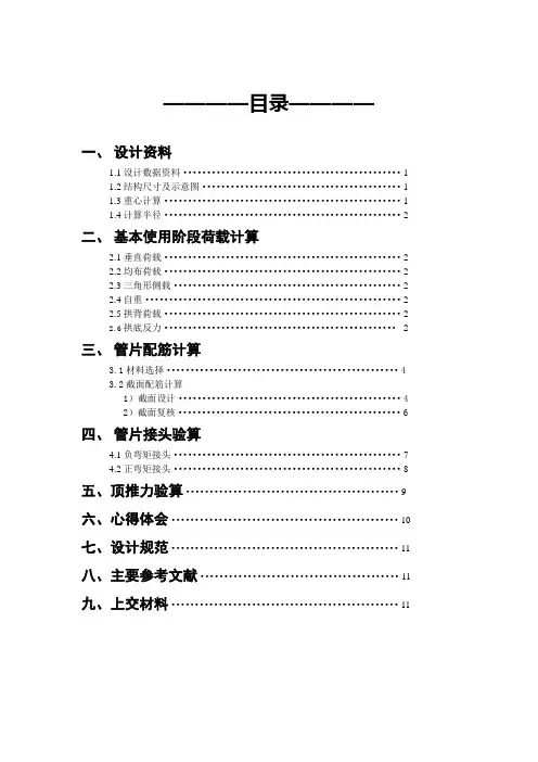
————目录————一、设计资料1.1设计数据资料 (1)1.2结构尺寸及示意图 (1)1.3重心计算 (1)1.4计算半径 (2)二、基本使用阶段荷载计算2.1垂直荷载 (2)2.2均布荷载 (2)2.3三角形侧载 (2)2.4自重 (2)2.5拱背荷载 (2)2.6拱底反力 (2)三、管片配筋计算3.1材料选择 (4)3.2截面配筋计算1)截面设计 (4)2)截面复核 (6)四、管片接头验算4.1负弯矩接头 (7)4.2正弯矩接头 (8)五、顶推力验算 (9)六、心得体会 (10)七、设计规范 (11)八、主要参考文献 (11)九、上交材料 (11)盾构管片课程设计一、设计资料教师评阅:1.1设计数据资料管片外径11.5m管片内径10.3m覆土深度20.1m土层容重14.1kN/m³饱和容重19.1 kN/m³地下水位1.1m土层内摩擦角17.1°土层粘聚力 24 kN/㎡1.2结构尺寸及示意图1.3重心计算盾构管片课程设计教师评阅: 重心z=300mm1.4计算半径r=5.15+0.3=5.45m二、基本使用阶段荷载计算2.1垂直荷载q=1.1×1.41+(20.1-1.1)×(1.91-1)=18.84t/㎡2.2均布荷载p1=18.84×tan²(45-17.1/2)-2×2.4×tan(45-17.1/2)=6.73 t/㎡2.3三角形侧载p2=2×5.45×tan²(45-17.1/2)×0.91=5.41 t/㎡2.4自重g=2.6×0.6=1.56 t/㎡2.5拱背荷载G=2(1-π/4)×5.45²×0.91=11.62 t/㎡2.6拱底反力Pr=18.84+1.56π+0.2146×5.45×0.91-π/2×5.45×1=16.24 t/㎡计算的M和N见下表。
隧道衬砌结构设计课程设计一、课程目标知识目标:1. 理解隧道衬砌结构的基本概念、分类和作用;2. 掌握隧道衬砌结构设计的基本原理和方法;3. 了解隧道衬砌结构施工技术及其质量控制措施;4. 了解隧道衬砌结构在工程中的应用及发展趋势。
技能目标:1. 能够分析隧道衬砌结构设计中的主要荷载及其作用机理;2. 能够运用专业知识进行隧道衬砌结构的设计计算;3. 能够根据设计要求,合理选择隧道衬砌结构材料和施工工艺;4. 能够对隧道衬砌结构设计进行合理的优化,提高结构性能和经济效益。
情感态度价值观目标:1. 培养学生热爱工程专业,增强对隧道工程建设的责任感和使命感;2. 培养学生严谨的科学态度和团队合作精神,提高解决实际问题的能力;3. 增强学生环保意识,让学生认识到隧道衬砌结构设计在资源利用和环境保护方面的重要性;4. 激发学生创新意识,鼓励学生探索隧道衬砌结构设计的新方法和新工艺。
本课程针对高年级土木工程专业学生,结合课程性质、学生特点和教学要求,明确以上课程目标,旨在使学生在掌握基本理论知识的基础上,提高解决实际工程问题的能力,为将来从事隧道工程设计和管理奠定坚实基础。
通过对课程目标的分解和实现,培养学生成为具有专业知识、实践技能和创新精神的土木工程人才。
二、教学内容1. 隧道衬砌结构基本概念:包括隧道衬砌结构的定义、分类、功能及其在隧道工程中的重要性;参考教材章节:第一章第一节。
2. 隧道衬砌结构设计原理:介绍隧道衬砌结构设计的基本原理、设计方法及主要设计规范;参考教材章节:第二章。
3. 隧道衬砌结构设计计算:详细讲解隧道衬砌结构设计中的荷载分析、内力计算、截面设计等;参考教材章节:第三章。
4. 隧道衬砌结构材料与施工技术:介绍隧道衬砌结构常用材料及其性能要求,探讨施工工艺及质量控制措施;参考教材章节:第四章。
5. 隧道衬砌结构设计实例分析:分析典型隧道衬砌结构设计案例,使学生掌握实际工程设计方法;参考教材章节:第五章。


隧道工程英语专业词汇隧道工程tunnel engineering隧道tunnel铁路隧道railway tunnel公路隧道highway tunnel地铁隧道subway tunnel;underground railway tunnel;metro tunnel 人行隧道pedestrian tunnel水工隧洞hydraulic tunnel输水隧道raulic tunnel山岭隧道mountain tunnel水下隧道subaqueous tunnel海底隧道水下隧道submarinetunnel;underwater tunnel 土质隧道earth tunnel岩石隧道rock tunnel浅埋隧道shallow tunnel;shallow-depthtunnel;s hallow burying tunnel深埋隧道deeptunnel;deep-depthtunnel;dee p burying tunnel偏压隧道unsymmetrical loading tunnel马蹄形隧道拱形隧道horse-shoe tunnel;arch tunnel圆形隧道circular tunnel矩形隧道rectangular section tunnel 大断面隧道largecross-section tunnel长隧道long tunnel双线隧道twin-track tunnel;double track tunnel曲线隧道curved tunnel明洞open tunnel;open cut tunnel;tunnel without cover;gallery隧道勘测tunnel survey超前探测drift boring工程地质勘测工程地质勘探engineering geological prospecting隧道测量tunnel survey施工测量construction survey断面测量section survey隧道设计tunnel design隧道断面tunnel section安全系数safety coefficient隧道力学tunnel mechanics隧道结构tunnel structure隧道洞口设施facilities of tunnel portal 边墙side wall拱顶arch crown拱圈tunnel arch 仰拱inverted arch底板base plate;floor隧道埋深depth of tunnel隧道群tunnel group隧道施工tunnel construction隧道开挖tunnel excavation分部开挖partial excavation大断面开挖large cross-section excavation全断面开挖full face tunnelling开挖面excavated surface隧道施工方法tunnel construction method 钻爆法drilling and blasting method 新奥法natm;newaustriantunnelling method盾构法shield driving method;shield method顶进法pipe jacking method;jack-in method浅埋暗挖法sallow buried-tunnelling method明挖法cut and cover tunneling;open cut method地下连续墙法underground diaphragm wall method;underground wall method冻结法freezing method沉埋法immersed tube method管棚法pipe-shed method综合机械化掘进comprehensive mechanized excavation辅助坑道auxiliary adit;service gallery 平行坑道parallel adit竖井shaft斜井sloping shaft;inclined shaft 导坑heading衬砌工艺lining process喷锚锚喷anchor bolt spray;anchor bolt-spray管段tube section接缝joint地层加固reinforcing of natural ground 弃碴ballast piling施工监控construction monitor control 超挖overbreak欠挖underbreak施工进度construction progress隧道贯通tunnel holing-through工期work period隧道施工机械tunnel construction machinery隧道掘进机tunnellingmachine;tunnelbor ing machine;tbm单臂掘进机single cantilever tunnelling machine全断面掘进机full face tunnel boring machine隧道钻眼爆破机械machine for tunnel drilling and blasting operation装碴运输机械loading-conveying ballast equipment衬砌机械lining mechanism钢模板steel form模板台车formworking jumbo混凝土喷射机砼喷射机concrete sprayer盾构shield泥水盾构slurry shield气压盾构air pressure shield挤压闭胸盾构shotcrete closed shield 土压平衡盾构soil pressure balancing shield 注浆机械grouting machine凿岩机rock drilling machine;air hammer drill凿岩台车drill jumbo;rock drilling jumbo围岩surrounding rock围岩分类surrounding rock classification围岩加固surrounding rock consolidation围岩稳定surrounding rock stability围岩应力surrounding rock stress围岩压力pressure of surrounding rock 山体压力围岩压力ground pressure;surrounding rock pressure围岩变形surrounding rock deformation围岩破坏surrounding rock failure软弱围岩weak surrounding rock支护support锚喷支护anchor bolt-spray support 锚杆支护anchor bolt-support;anchor bolt support喷射混凝土支护喷射砼支护shotcrete support;sprayed concrete support配筋喷射混凝土支护配筋喷射砼支护reinforced sprayed concrete support钢架喷射混凝土支护钢架喷射砼支护rigid-frame shotcrete support掘进工作面支护excavation face support超前支护advance support管棚支护pipe-shed support;pipe roofing support胶结型锚杆adhesive anchor bolt砂浆锚杆mortar bolt树脂锚杆resin anchored bolt摩擦型锚杆friction anchor bolt楔缝式锚杆slit wedge type rock bolt涨壳式锚杆expansion type anchor bolt 机械型锚杆mechanical anchor bolt预应力锚杆prestressed anchor bolt土层锚杆soil bolt岩石锚杆rock bolt衬砌lining整体式衬砌integral tunnel lining;integral lining拼装式衬砌precast lining组合衬砌composite lining挤压混凝土衬砌挤压砼衬砌shotcrete tunnellining;extruding concrete tunnel lining混凝土衬砌砼衬砌concrete lining喷锚衬砌shotcrete and boltlining;shotcrete bolt lining 隧道通风tunnel ventilation施工通风construction ventilation运营通风operation ventilation机械通风mechanical ventilation自然通风natural ventilation隧道射流式通风隧道射流通风efflux ventilation for tunnel;tunnel efflux ventilation;tunnel injector type ventilation隧道通风帘幕curtain for tunnel ventilation;ventilation curtain 通风设备ventilation equipment隧道照明tunnel illumination;tunnel lighting照明设备lighting equipment隧道防水Tunnelwaterproofing;waterpr oofing of tunnel防水板waterproofingboard;waterproofboard;water proof sheet防水材料waterproof material隧道排水tunnel drainage排水设备drainage facilites隧道病害tunnel defect衬砌裂损lining split;lining **ing隧道漏水water leakage of tunnel;tunnel leak坍方landslide;slip地面塌陷land yielding涌水gushing water隧道养护tunnel maintenance堵漏leaking stoppage注浆grouting化学注浆chemical grouting防寒cold-proof整治regulation限界检查clearance examination;checking of clearance;clearance check measurement隧道管理系统tunnelling management system隧道环境tunnel environment隧道试验隧道实验tunnel test试验段实验段test section隧道监控量测隧道监控测量tunnel monitoring measurement收敛convergence隧道安全tunnel safety隧道防火tunnel fire proofing火灾fire hazard消防fire fighting隧道防灾设施tunnel disaster prevention equipment;tunnelanti-disaster equipment 报警装置报警器alarming device;warning device通过隧道passing tunnel避车洞refuge hole避难洞避车洞refuge recess;refuge hole 电气化铁道工程电气化铁路工程electrified railway construction电气化铁道电气化铁路electrified railway直流电气化铁道dc electrified railway交流电气化铁道交流电气化铁路a.c.electrification railway低频电气化铁道low frequency electrified railway工频电气化铁道工频电气化铁路industry frequency electrified railway电压制voltage system电流制current system。
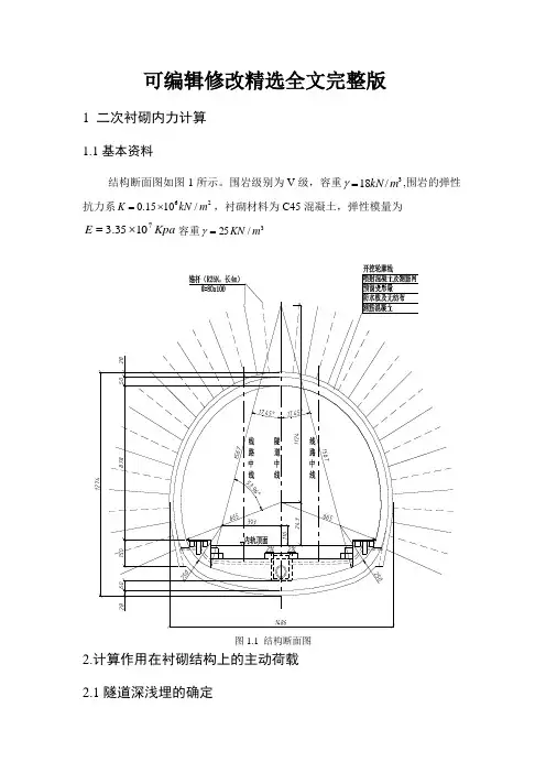
可编辑修改精选全文完整版1 二次衬砌内力计算1.1基本资料结构断面图如图1所示。
围岩级别为V 级,容重3/18m kN =γ,围岩的弹性抗力系620.1510/K kN m =⨯,衬砌材料为C45混凝土,弹性模量为Kpa E 71035.3⨯=容重3/25m KN =γ图1.1 结构断面图2.计算作用在衬砌结构上的主动荷载 2.1隧道深浅埋的确定坍落拱高度按下式计算:[])5(1245.01-+⨯⨯=-t s qB i hⅤ级围岩,s=5;B>5,i=0.1[]m h q 299.14)586.14(1.01245.04=-⨯+⨯⨯=浅埋隧道分界深度:m h H q P 748.355.2=⨯=因为m H m H m h p q748.3534299.14=<=<=,所以是浅埋隧道2.2竖直和水平荷载垂直力:取00246.0,40,86.14,34=====g g t m B m Hφθφ744.2445.0839.0839.0)1704.0(839.0tan tan tan )1(tan tan tan 2=-⨯++=-++=θφφφφβg gg g[]283.0tan tan )tan (tan tan 1tan tan tan =+-+-=θφθφββφβλg g gm kN B H H q t /567.435)445.0283.086.14341(3418)tan 1(=⨯⨯-⨯⨯=⨯⨯-⨯=θλγ水平力:mkN H e /196.173283.034181=⨯⨯==λγ()m kN h e /094.238283.03474.12182=⨯+⨯==λγ()()m kN e e e /645.205094.238196.173212121=+⨯=+⨯=3.半拱轴线长度3.1衬砌的几何尺寸内轮廓线半径:m r m r 5.265.621==,内径21r r ,所画圆曲线端点截面与竖直轴线的夹角:0201140,109==ϕϕ拱顶截面厚度:m d 5.00=, 拱底截面厚度:m d n 6.0=。
隧道工程课程设计一、工程概况某地区一暗挖双线马蹄形隧道,埋深h=125m,围岩等级为v级,地层平均容重16。
0 kN/m3。
宽度B=13.08m,隧道采用复合式衬砌形式,衬砌厚度为0.42m,配筋采用Ф22@200mm,钢材采用HRB335,钢筋保护层厚度50mm。
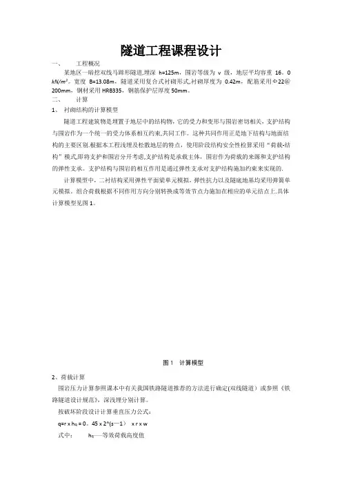
二、计算1、衬砌结构的计算模型隧道工程建筑物是埋置于地层中的结构物,它的受力和变形与围岩密切相关,支护结构与围岩作为一个统一的受力体系相互约束,共同工作。
这种共同作用正是地下结构与地面结构的主要区别.根据本工程浅埋及松散地层的特点,使用阶段结构安全性检算采用“荷载-结构”模式,即将支护和围岩分开考虑,支护结构是承载主体,围岩作为荷载的来源和支护结构的弹性支承。
支护结构与围岩的相互作用是通过弹性支承对支护结构施加约束来实现的.计算模型中,二衬结构采用弹性平面梁单元模拟,弹性抗力以及隧底地基均采用弹簧单元模拟。
组合荷载根据不同作用方向分别转换成等效节点力施加在相应的单元结点上.具体计算模型见图1。
图1 计算模型2、荷载计算围岩压力计算参照课本中有关我国铁路隧道推荐的方法进行确定(双线隧道)或参照《铁路隧道设计规范》,深浅埋分别计算。
按破坏阶段设计计算垂直压力公式:q=r x h q = 0。
45 x 2^(s—1)x r x w式中:h q——等效荷载高度值S——围岩级别r—-围岩的容重w—-宽度影响系数,其值为w=1+i(B—5)计算得,q=0。
45x2^(5-1)x16000x1。
805=2.082816e6N/m水平均布松动压力系数取0。
3,则e=0.3q=0.0634e6N/m3、ANSYS操作命令流!荷载——结构方法计算(马蹄形断面)finish !退出当前处理程序/clear !清除以前数据,重新开始一个新的分析/COM,Structural !定义分析类型,结构分析(热分析、流体分析等)/prep7 !进入前处理器*AFUN,deg !定义角度单位为度(缺省为弧度,RAD)! 定义建模及材料参数的一些变量值*set,Py,2。
隧道工程相关专业英语词汇隧道tunnel 隧道工程tunnel engineering 铁道隧道railway tunnel 公路隧道highway tunnel 地铁隧道subway tunnel ; underground railway tunnel; metro tunnel 人行隧道pedestrian tunnel 水工隧洞;输水隧道hydraulic tunnel 山岭隧道mountain tunnel 水下隧道subaqueous tunnel 海底隧道;水下隧道submarine tunnel;underwater tunnel 土质隧道earth tunnel 岩石隧道rock tunnel 浅埋隧道shallow tunnel;shallow-depth tunnel ; shallow burying tunnel 深埋隧道deep tunnel;deep-depth tunnel ; deep burying tunnel 偏压隧道unsymmetrical loading tunnel 马蹄形隧道;拱形隧道horse-shoe tunnel ; arch tunnel 圆形隧道circular tunnel矩形隧道rectangular section tunnel 大断面隧道largecross-section tunnel 长隧道long tunnel双线隧道twin-track tunnel ; double track tunnel 曲线隧道curved tunnel 明洞open tunnel;open cut tunnel;tunnel without cover;gallery 隧道施工方法tunnel construction method 钻爆法drilling and blasting method 新奥法natm;new austrian tunnelling method 盾构法shield driving method;shield method 顶进法pipe jacking method ; jack-in method 浅埋暗挖法sallow buried-tunnelling method 明挖法cut and covertunneling;opencut method 地下连续墙法underground diaphragm wall method; underground wall method 冻结法freezing method 沉埋法immersed tube method 管棚法pipe-shed method隧道勘测tunnel survey超前探测drift boring 工程地质勘测;工程地质勘探engineering geological prospecting 隧道测量tunnel survey 施工测量construction survey 断面测量section survey 隧道设计tunnel design 隧道断面tunnel section 安全系数safety coefficient 隧道力学tunnel mechanics隧道结构tunnel structure隧道洞口设施facilities of tunnel portal 边墙side wall 拱顶arch crown 拱圈tunnel arch 仰拱inverted arch 底板base plate;floor 隧道埋深depth of tunnel 隧道群tunnel group隧道施工tunnel construction隧道开挖tunnel excavation分部开挖partial excavation大断面开挖large cross-section excavation 全断面开挖full face tunnelling 开挖面excavated surface围岩压力ground pressure;surrounding rock pressure 围岩变形surrounding rock deformation 围岩破坏surrounding rock failure 软弱围岩weak surrounding rock支护support锚喷支护anchor bolt-spray support锚杆支护anchor bolt-support;anchor bolt support 喷射混凝土支护;喷射砼支护shotcrete support;sprayed concrete support 配筋喷射混凝土支护;配筋喷射砼支护reinforced sprayed concrete support 钢架喷射混凝土支护;钢架喷射砼支护rigid-frame shotcrete support掘进工作面支护excavation face support 超前支护advance support 管棚支护pipe-shed support;pipe roofing support 胶结型锚杆adhesive anchor bolt 砂浆锚杆mortar bolt 树脂锚杆resin anchored bolt 摩擦型锚杆friction anchor bolt 楔缝式锚杆slit wedge type rock bolt 涨壳式锚杆expansion typeanchor bolt 机械型锚杆mechanical anchor bolt 预应力锚杆prestressed anchor bolt 土层锚杆soil bolt 岩石锚杆rock bolt衬砌lining整体式衬砌integral tunnel lining;integral lining 拼装式衬砌precast lining 组合衬砌composite lining挤压混凝土衬砌shotcrete tunnel lining ; extruding concrete tunnel lining 混凝土衬砌;砼衬砌concrete lining 喷锚衬砌shotcrete and bolt lining;shotcrete bolt lining隧道通风tunnel ventilation施工通风construction ventilation运营通风operation ventilation机械通风mechanical ventilation自然通风natural ventilation隧道射流式通风efflux ventilation for tunnel ;tunnel efflux ventilation;tunnel injector type ventilation 隧道通风帘幕curtain for tunnel ventilation;ventilation curtain 通风设备ventilation equipment隧道照明tunnel illuminationtunnel lighting照明设备lighting equipment隧道防水tunnel waterproofing;waterproofing of tunnel防水板waterproofing board;waterproof board;waterproof sheet防水材料waterproof material隧道排水tunnel drainage排水设备drainage facilites隧道病害tunnel defect衬砌裂损lining split;隧道漏水water leakage of tunnel;tunnel leak坍方landslide;slip地面塌陷land yielding涌水gushing water隧道养护tunnel maintenance堵漏leaking stoppage注浆grouting化学注浆chemical grouting防寒cold-proof整治regulation限界检查clearance examination;checking of clearance;clearance check measurement 隧道管理系统tunnelling management system 隧道环境tunnel environment隧道试验;隧道实验tunnel test试验段;实验段test section隧道监控量测;隧道监控测量tunnel monitoring measurement 收敛convergence隧道安全tunnel safety隧道防火tunnel fire proofing火灾fire hazard 消防fire fighting 隧道防灾设施tunneldisaster prevention equipment; tunnel anti-disaster equipment 报警装置;报警器alarming device;warning device 通过隧道passing tunnel 避车洞refuge hole 避难洞;避车洞refugerecess;refuge hole电气化铁道工程; 电气化铁路工程electrified railway construction直流电气化铁道dc electrified railway交流电气化铁道;交流电气化铁路 a.c.electrification railway 低频电气化铁道low frequency electrified railway 工频电气化铁路industry frequency electrified railway 电压制voltage system电流制current system。
Part 1 General words岩土工程Geotechnical engineering基础工程Foundation engineering土soil ,earth`土力学soil mechanics周期荷载cyclic loading卸载,再加载reloading粘弹性地基viscoelastic foundation粘滞阻尼viscous damping剪切模量shear modulus土动力学soil dynamics应力路径stress path砌块block底板标高floor elevation顶板标高roof elevation绝对标高absolute elevation相对标高relative elevation钢结构steel structure抗拉强度tensile strength伸长率elongation屈服强度yield strength有色金属non-ferrous metals喷射混凝土shotcrete勘察survey;investigation工程地质engineering geology风化花岗岩 decomposed granitePart 2 Types of soil残积土residual soil地下水groundwater地下水位groundwater level /groundwater table粘土矿物clay minerals次生矿物secondary minerals滑坡landslide钻孔柱状图bore hole columnar section 工程地质勘察engineering geologic investigation漂石boulder卵石cobble砂石gravel砾砂gravelly sand粗砂coarse sand中砂medium sand细砂fine sand 粉土silty sand粘性土clayey soil粘土clay粉质粘土silty clay砂质粉土sandy silt粘质粉土clayey silt饱和土saturated soil非饱和土unsaturated soil填土filled soilPart 3 Permeability and seepage达西定律Darcy’s law管涌piping流土flowing soil砂沸sand boiling流网flow net渗流seepage渗漏leakage渗透压力seepage (force) pressure渗透性permeability水力梯度hydraulic gradient渗透系数coefficient of permeability Part 4 Deformation and stress of foundation软土soft soil打入桩(负)摩阻力(negative) skin friction of driven pile有效应力effective stress总应力total stress十字板抗剪强度field vane shear strength低活性low activity灵敏度sensitivity三轴试验triaxial test基础设计foundation design再压缩recompaction承载力bearing capacity土体soil mass接触压力contact pressure集中荷载concentrated load半无限弹性体 a semi-infinite elastic solid均质homogeneous各向同性isotropic条基strip footing方形独立基础square spread footing下卧层(土)underlying soil (stratum ,strata)恒载/静载dead load持续荷载sustained load活载live load短期瞬时荷载short –term transient load长期荷载long-term transient load折算荷载reduced load沉降settlement变形deformation套管casing堤(防)dike=dyke粘粒粒组clay fraction物理性质physical properties路基subgrade级配良好土well-graded soil级配不良土poorly-graded soil筛子sieve摩尔-库仑破坏条件Mohr-Coulomb failure condition有限元法FEM=finite element method 极限平衡法limit equilibrium method 孔隙水压力pore water pressure先期固结压力preconsolidation pressure压缩模量modulus of compressibility 压缩系数coefficent of compressibility 压缩指数compression index回弹指数swelling index自重应力geostatic stress附加应力additional stress最终沉降final settlement滑移线slip linePart 5 Excavation and dewatering of foundation开挖excavation降水dewatering基坑失稳failure of foundation基坑围护bracing of foundation pit (基坑)底隆起bottom heave=basal heave挡土墙retaining wall 孔压分布pore-pressure distribution降低地下水位法dewatering method井点系统well point system深井点deep well point真空井点vacuum well point支撑围护braced cuts支撑开挖braced excavation支撑挡板braced sheetingPart 6 Deep foundation桩基础pile foundation灌注桩cast –in-place pile沉管灌注桩diving casting cast-in-place pile钻孔桩bored pile机控异型灌注桩special-shaped cast-in-place pile嵌岩灌注桩piles set into rock夯扩桩rammed bulb pile钻孔墩基础belled pier foundation钻孔扩底墩drilled-pier foundation预制混凝土桩precast concrete pile钢桩steel pile钢管桩steel pipe pile钢板桩steel sheet pile预应力混凝土桩prestressed concrete pile预应力混凝土管桩prestressed concrete pipe pile沉井(箱) caisson foundation地下连续墙diaphragm摩擦桩friction pile端承桩end-bearing pile波动方程分析wave equation analysis 承台pile cap单桩承载力bearing capacity of single pile单桩横向载荷试验lateral pile load test 单桩横向极限承载力ultimate lateral resistance of single pile单桩竖向静荷载试验static load test of pile单桩竖向容许承载力vertical allowable load capacity低桩承台low pile cap高桩承台high-rise pile cap单桩抗拔极限承载力vertical ultimate uplift resistance of single pile静压桩silent piling抗拔桩uplift pile抗滑桩anti-slide pile群桩pile groups群桩效率系数(η)efficiency factor of pile groups群桩效应efficiency of pile groups桩基动测dynamic pile testing最后贯入度final set桩动荷载试验dynamic load test of pile 桩的完整性试验pile integrity test桩头pile head=butt桩端(头)pile tip=pile point=pile toe 桩距pile spacing桩位布置图pile plan桩的布置arrangement of piles =pile layout群桩作用group action桩端阻end bearing=tip resistance桩侧阻skin(side) friction=shaft resistance桩垫pile cushion打桩(振动)pile driving(by vibration) 拔桩试验pile pulling test桩靴pile shoe打桩噪音pile noise打桩机pile rigPart 7 Ground treatment建筑地基处理技术规范technical code for ground treatment of building垫层法cushion method预压法preloading method强夯法dynamic compaction method强夯置换法dynamic compaction replacement method振冲法vibroflotation method砂石桩sand-gravel pile /pile-stone column水泥粉煤灰碎石桩cement-flyash-gravel pile(CFG)水泥土搅拌桩cement mixing pile 水泥桩cement column石灰桩lime pile /lime column高压喷射注浆法jet grouting method 夯实水泥土桩rammed-cement-soil pile灰土挤密桩lime-soil compaction pile /lime-soil compacted column化学加固法chemical stabilization method表层压实法surface compaction method超载预压法surcharge preloading method真空预压法vacuum preloading method袋装砂井法sand wick method土工织物geofabric /geotextile复合地基composite foundation加筋法reinforcement method降低地下水固结法dewatering consolidation method冷热处理法freezing and heating method膨胀土地基处理expansive ground treatment山区地基处理ground treatment in mountain area湿陷性黄土地基处理collapsible loess treatment人工地基artificial foundation天然地基natural foundation褥垫pillow软土地基soft clay ground砂井sand drain树根桩root pile塑料排水带plastic drain碎石桩stone column/gravel pile(复合地基)置换率(composite foundation) replacement ratioPart 8固结consolidation太沙基固结理论Terzzaghi’s consolidation theory巴隆固结理论Barraon’s consolidationtheory比奥固结理论Biot’s consolidation theory超固结比over consolidation ration (OCR)超固结土overconsolidation soil超孔压力excess pore water pressure多维固结multi-dimensional consolidation一维固结one-dimensional consolidation主固结primary consolidation次固结secondary consolidation固结度degree of consolidation固结试验consolidation test固结曲线consolidation curve时间因子time factor Tv固结系数coefficient of consolidation 前期固结压力preconsolidation pressure有效应力原理principle of effective stressK0固结consolidation under K0 conditionPart 9 抗剪强度shear strength不排水抗剪强度undrained shear strength残余强度residual strength长期强度long-term strength峰值强度peak strength剪胀dilatation抗剪强度有效应力法effective stress approach of shear strength抗剪强度总应力法total stress approach of shear strength莫尔-库仑理论Mohr-Coulomb theory内摩擦角angle of internal friction粘聚力cohesion破坏准则failure criterion十字板抗剪强度vane strength无侧限抗压强度unconfined compression strength有效应力破坏包线effective stress failure envelopePart 10 Constitutive model弹性模型Elastic model非线性弹性模型Nonlinear elastic model弹塑性模型Elastoplastic model粘弹性模型Viscoelastic model边界面模型Boundary surface model 邓肯-张模型Duncan-Chang model 刚塑性模型Rigid plastic model帽模型Cap model加工软化Work softening加工硬化Work hardening剑桥模型Cambridge model理想弹塑性模型Ideal elastoplastic model莫尔-库仑屈服准则Mohr-Coulomb yield criterion屈服面Yield surface弹性半空间地基模型Elastic half-space foundation model弹性模量Elastic modulusPart 11 Bearing capacity of foundation soil冲切破坏Punching shear failure整体剪切破坏General shear failure局部剪切破坏Local shear failure极限平衡状态State of limit equilibrium地基稳定性Stability of soil/rock foundation地基极限承载力Ultimate bearing capacity of soil/rock foundation地基容许承载力Allowable bearing capacity of soil/rock foundationPart 12 earth pressure and slope stability analysis主动土压力Active earth pressure被动土压力Passive earth pressure静止土压力Earth pressure at rest休止角Angle of repose边坡稳定安全系数Safety factor of slope条分法Slices methodPart 13 retaining wall挡土墙稳定性Stability of retaining wall基础墙Foundation wall扶壁式挡土墙Counter retaining wall 悬臂式挡土墙Cantilever retaining wall悬臂式板桩墙Cantilever sheet pile wall重力式挡土墙Gravity retaining wall 锚定板挡土墙Anchored plate retaining wall锚定板板桩墙Anchored sheet pile wall Part 14 Soil test高压固结试验High pressure consolidation testK0固结试验Consolidation under K0 condition变水头渗透试验Falling head permeability test不固结不排水三轴试验Unconsolidated-undrained triaxial test 固结不排水/排水三轴试验Consolidated undrained/drained triaxial test击实试验Compaction test固结快剪试验Consolidated quick direct shear test快剪试验Quick direct shear test土工模型试验Geotechnical model test 离心模型试验Centrifugal model test 直剪仪Direct shear apparatusPart 15 In situ test标准贯入试验Standard penetration test (SPT)表面波试验Surface wave test(SWT) 动力触探试验Dynamic penetration test(DPT)静力触探试验Static cone penetration test跨孔试验Cross-hole test螺旋板载荷试验Screw plate test旁压试验Pressuremeter test 轻便触探试验Light sounding test深层沉降观测Deep settlement measurement现场渗透试验Field permeability test 原位空隙水压量测In-situ pore water pressure measurement原位(土、岩石)试验In-situ soil/rock test直剪试验Direct shear test直接单剪试验Direct simple shear test 动三轴试验Dynamic triaxial test自(共)振柱试验Free(resonance) vibration column test隧道Tunnel水平隧道Horizontal gallery明挖法Cut and cover沉管法Immersed tube入口隧道或引道隧道Access tunnel竖shaft斜井Inclined shaft洞室cavern天然洞室Natural cavern人工洞室Artificial cavern地下综合建筑Underground complex 尺寸Size,dimension特小断面Mini section小断面Small section中断面Medium section特大断面Very large section短Short length中长Medium length长大Long length特长大Very long length断面形状Section shape圆形Circular shape马蹄形Horseshoe shape矩形Rectangular shape卵形Egg shape箱形Box shape内部净空断面形状Inside shape开挖断面形状Outside or excavation shape埋深Tunnel depth明挖回填Cut and cover浅埋Shallow depth中埋Medium depth深埋Deep depth特深埋Very deep depth用途Purpose or use调查investigation地质调查Ground investigation导洞Pilot tunnel调查孔或坑道Pilot bore铁路rail干线Main line地铁metro公路road人行道pedestrian车站Station上水道Water supply水利发电Hydraulic power有压与无压隧洞Pressure or non pressure tunnels分水渠River diversion洪水Storm water排水Drainage水渠Aqueduct冷气cooling air冷却水排水Cooling water outfall航道navigation下水道Sewerage地域暖气District heating电缆cable热水Hot water电力-通信Power-telecommunication 通风Ventilation煤气Gas工厂factory发电所Generating station储藏storage流体和固体储藏Fluids and solids storage停车parking办公室,商店Office, shop军事Military人防Defence,protection多目的,多功能Multi service采矿Mining 地下建筑物各部分名称Parts of cross section仰拱Invert arch底板floor拱部或拱顶部roof拱顶crown拱脚Springer拱肩shoulders刹尖key边墙wall墙脚feet腿部leg膝部knee开挖面或掌子面face形状shape衬砌lining曲隅部bend交叉部crossing正面部Face, front入口部access洞门portal接头部junction分岔部bifurcation开口部Opening window加宽部enlargement避难洞Recess筛子sieve围岩Surrounding rock地质学geology水文地质学hydrogeology岩石力学Rock mechanics土力学Soil mechanics地震活动Seismicity钻孔或钻探boring地质物理调查Geophysical investigation室内试验Laboratory test现场试验In situ test事前调查Probing ahead地质勘探Geologic exploration围岩的性质Nature of ground硬岩Hard rock完整岩石Sound rock风化岩Weathered rock破碎岩Fissured rock软弱围岩Soft ground塑性围岩Plastic ground流动围岩Running ground减压区Decompressed zone混合围岩Mixed ground卵石boulder夹层seam层理bedding节理Joint不透水围岩Impervious ground透水围岩Pervious ground蠕变creep风化,蚀变alteration透水性permeability地下水Ground water湿度moisture岩溶karst断层fault围岩的物理力学性质Ground character密度density比重Specific gravity磨损度abrasivity溶解度solubility可钻性Drillability抗压强度Compressive strength抗拉强度Tensile strength抗剪强度Shear strength内摩擦力Internal friction粘结力cohesion剪胀swelling收缩shrinkage地压Ground pressure弹性系数Modulus of elasticity冲击阻力Impact resistance孔隙率Porosity ratio硬度hardness设计Design分析Analysis计算calculation经济比较Economic study标准化Standardization计划Plan, planing program 设计数据Design data垂直荷载Vertical load水平荷载Horizontal load 浮力Uplift。
Underground Structure Course DesigningA Design of Shield Tunnel LiningCollege Civil EngineeringMajor Department of Geotechnical EngineeringStudent No.100xxxName xxxDirector xxxDate6th Sep. 2021Part One: Design Data1 Function of TunnelThe planned tunnel is to be used as a subway tunnel.2 Design Conditions(1)Dimensions of SegmentType of segment: RC , Flat typeDiameter of segmental lining: D 0=9500mmRadius of centroid of segmental lining: R c =4550mm Width of segment: b=1200mm Thickness of segment: t=400mm (2)Ground Conditions Overburden: H=12.3mGroundwater table: G.L.+0.6m =12.3+0.6=12.9m N Value: N=50Unit weight of soil: γ=18kN/m 3Submerged unit weight of soil: γ'=8kN/m 3 Angle of internal friction of soil: φ=30o Cohesion of soil: c =0 kN/m 2Coefficient of reaction: k=50MN/m 3Coefficient of lateral earth pressure: λ=0.4 Surcharge: P 0=39.7kN/m 2 Soil condition: Sandy (3)MaterialsThe grade of concrete: C30Nominal strength: f ck =20.1N/mm 2Allowable compressive strength: f c =14.3N/mm 2 Allowable tensile strength: f t =1.43N/mm 2 The type of steel bars: HRB335Allowable strength: f y = f y ’= 300N/mm 2 Bolt:Yield strength: f By =240N/mm 2 Shear strength: B τ=150N/mm 23 Design Method Requirement(1)How to check member forces: ① Elastic equation method(option)② Force method based on the textbook (must do this)③ Bedded frame model(Beam element with elastic support)(option)0P K =constant of rotation spring for positive moment at joint=18070/kN m rad⋅Figure 1 Judgment of tunnel type0N K =constant of rotation spring for negative moment at joint=32100/kN m rad ⋅ (2)How to calculate reinforcement for segmental lining:Limit state method①Based on the national code GB50010-2002 for reinforcement concrete design. ②Please choose the grade of concrete and the type of steel rebars.Bolt: yield strength 2240/By f MN m =shear strength 2150/B MN m τ=Part Two: Computation by Force Method1 Load Conditions(1)Judgment of Tunnel Type (by Terzaghi’s formula) 1018030cot() 4.75cot()8.238484B R m πφ=+=⨯+=42πφ+[]()1100111/()1exp tan exp tan tan 8.231012.312.31exp tan 3039.7exp tan 30tan 308.238.2324.9912.3B C B H H h P B B m H mγφφφ⎡⎤-⎛⎫⎛⎫=--+-⎢⎥ ⎪ ⎪⎝⎭⎝⎭⎣⎦⨯-⎡⎤⎛⎫⎛⎫=--⨯+⨯-⨯ ⎪ ⎪⎢⎥⎝⎭⎝⎭⎣⎦=>= So the designed tunnel is a shallow tunnel .(2)Load Types and Partial FactorsTable 1 shows the loads should be considered in the design and corresponding partial factors.(3)Computation of LoadsComputational element is a 1.2 meter (width of segment) part along the longitudinal direction, and Figure 2 shows the load condition to compute member forces of the segmental lining.Figure 2 Load condition of the designed tunnel①Vertical Pressure at the Tunnel Crown Earth Pressure()()101.4 1.2 1.2 1.439.7 1.2812.3208.392/e P b P H kN m γ'=+=⨯⨯+⨯⨯=Water Pressure1 1.2 1.2 1.21012.9185.76/w w w p b H kN m γ==⨯⨯⨯= 111208.392185.76394.152/e w q p p kN m =+=+= 29.51.20.215 1.2 1.20.2151826.4708/2q b R kN m γ=⨯=⨯⨯⨯⨯= 112394.15226.4708420.6228/p q q kN m =+=+=②Vertical Pressure at the Tunnel Bottom21 1.2420.6228 1.2 1.2260.4467.6713/c p p b t kN m πγπ=+=+⨯⨯⨯=③Lateral Pressure at the Tunnel Crown Earth Pressure110.41.20.4208.392 1.2 1.2884.2784/22e e t q p b kN m λγ⎛⎫⎛⎫'=+=⨯+⨯⨯⨯= ⎪ ⎪⎝⎭⎝⎭Water Pressure()()1 1.2/2 1.2 1.21012.90.4/2188.64/w w w q b H t kN m γ=+=⨯⨯⨯+=31184.2784188.64272.9184/e w p q q kN m =+=+=④ Lateral Pressure at the Tunnel Bottom()()4 1.2 1.2 1.20.489.1109.1172.9728/c w c p b D D kN m λγγ'=+=⨯⨯⨯⨯+⨯=3434272.9184172.9728445.8912/p p p kN m +=+=+=Wherec D = Computational diameter 09.50.49.1D t m =-=-=⑤Average Self -weight5 1.2 1.2 1.2260.414.976/c p b t kN m γ==⨯⨯⨯=Wherec γ= Unit weight of RC segment 326/kN m =⑥Lateral Resistance PressureFigure 3 Simplified model diagram for calculation()()()()41334544737432240.04542420.6228272.9184445.891214.976 4.55240.8 3.010 6.4100.04547.210 4.551.946910c c p p p p R EI KR mπδηπ+----+=+⨯--+⨯⨯=⨯⨯⨯⨯⨯+⨯⨯⨯=⨯336010 1.946910 1.2140.1768/h p k b kN m δ-==⨯⨯⨯⨯=()2612cos h p p ϕ=- 344ππϕ⎛⎫≤≤⎪⎝⎭Whereδ= Displacement of lining at tunnel spring η= Reduction factor of model rigidity = 0.8E = Modulus of elasticity of segment = 423.010/N mm ⨯I = Moment of inertia of area of segment =33411.20.4 6.41012m -⨯⨯=⨯ k = Coefficient of reaction = 360/MN m260 1.272/K k b MN m ==⨯=ϕ= the angle of measured from the vertical direction around the tunnel2 Computation of Member ForcesFigure 4 shows the simplified model of the segmental lining.(1)Calculation Data18070/P K kN m rad θ= (if inside part of lining is tensile) 32100/K kN m rad θN = (if outside part of lining is tensile)43323.01010 6.410192000EI kN m -=⨯⨯⨯⨯=(2)Coefficients Calculation123411125n n n n n =+++=+++=NOTE: if the joint just located at 180 degree of the half -ring lining, then its stiffness contribution to the whole structure should be considered as half of the total value.41111()11 2.52 4.55 2.52 2.751101920001807032100ni i P N R R kN m EI K EI K K θθθπππδ---=⨯=+=++=++=⨯∑()2212()12311 2.826 1.6741cos 4.55 2.826 4.55 1.674 4.551.288101920001807032100n i i i P N R R R R R EI K EI K K kN θθθππδϕπ=--=+-=++⨯⨯⨯=++=⨯∑()33222222()13223313 5.122 1.6271cos 223 4.55 5.122 4.55 1.627 4.559.22910/21920001807032100ni i i P N R R R R R EI K EI K K m kNθθθππδϕπ=-=+-=++⨯⨯⨯⨯=++=⨯⨯∑322211111()12110.2650.860sin 4244.550.2650.860420.6228 4.550.52341920001807032100np i i i P N p R R p R p R EI K EI K K θθθππϕπ=⎛⎫∆=--=-++ ⎪⎝⎭⨯⎛⎫=-⨯⨯++=- ⎪⨯⎝⎭∑()()12322212112()12212()3()121sin 24230.3140.00012()224 4.5530.3140.00012467.6713420.6228 4.5522192000418070321000.np i i i n n P N p p R p p R EI K R p p R EI K K θθθπϕππ=++--⎛⎫∆=---- ⎪⎝⎭⎡⎤⎛⎫=---++⎢⎥ ⎪⎝⎭⎣⎦⎡⎤⎛⎫=--⨯⨯-++ ⎪⎢⎥⨯⎝⎭⎣⎦=-∑021124243 4.55 2.5610.814272.9184 4.55 1.25941920001807032100i P N EI K EI K K θθθπ=⎝⎭⨯⎛⎫=-⨯⨯++=- ⎪⨯⎝⎭()323244144()125150.7920.1451cos 2412245 4.550.7920.145172.9782 4.550.229241920001807032100n p i i i P N p R p R R p R EI K EI K K θθθππϕπ=⎛⎫∆=---=-++ ⎪⎝⎭⨯⎛⎫=-⨯⨯++=- ⎪⨯⎝⎭∑()221555()121 1.1360.952cos sin 11.1360.95214.976 4.550.011807032100np i i i i i PN p R p R K K K θθθϕϕϕ=⎛⎫∆=-+-=- ⎪⎝⎭⎛⎫=⨯⨯-= ⎪⎝⎭∑4143216()()112211cos(2)2cos cos 341.1940.239 4.55 1.1940.239140.1768 4.5519200018070321000.282n n n h h p i i i i i i n i n n h P N p R p R EI K K R p R EI K K θθθθπϕϕϕ-=+=-+⎡⎤⎛⎫∆=---++ ⎪⎢⎥⎝⎭⎣⎦⎛⎫⎛⎫=-++=-⨯⨯++ ⎪ ⎪⎝⎭⎝⎭=-∑∑()6111(0.523)(0.021)( 1.259)0.2290.01(0.282)2.304p pi i =∆=∆=-+-+-+-++-=-∑432311211()1310.3680.757sin (1cos )4244.550.3680.757420.6228 4.55 2.47941920001807032100n p i i i i P N p R p R R p R EI K EI K K mθθθππϕϕπ=⎛⎫∆=---=-++ ⎪⎝⎭⨯⎛⎫=-⨯⨯++=- ⎪⨯⎝⎭∑()()12432212122()13213()35()1(1cos )1sin 2432350.6130.00014()243 4.55350.6130.00014467.6713420.6228 4.5521920004318070321n p i i i i n n P N p p R p p R EI K R p p R EI K K θθθπϕϕππ=++--⎛⎫∆=----- ⎪⎝⎭⎡⎤⎛⎫=---++⎢⎥⎪⎝⎭⎣⎦⎛⎫=--⨯⨯-++⎪⨯⎝⎭∑000.187m⎡⎤⎢⎥⎣⎦=-134245 4.55 4.7540.871272.9184 4.559.85341920001807032100i P N EI K EI K K mθθθπ=⎝⎭⨯⎛⎫=-⨯⨯++=- ⎪⨯⎝⎭()434344244()1335135 1.4770.1631cos 96129635 4.55 1.4770.163172.9728 4.55 1.857961920001807032100n p i i i P N p R p R R p R EI K EI K K mθθθππϕπ=⎛⎫∆=---=-++ ⎪⎝⎭⨯⎛⎫=-⨯⨯++=- ⎪⨯⎝⎭∑()()435255()135311cos cos sin 14 2.3420.8434 4.552.3420.84314.976 4.550.17241920001807032100np i i i i i i P N p R p REIK R p R EIK K mθθθπϕϕϕϕππ=∆=--+-⎛⎫=+- ⎪⎝⎭⨯⎛⎫=⨯⨯+-= ⎪⨯⎝⎭∑ ()4144326()13()1331cos 22cos 1cos 3341cos 1cos 3 2.2180.27633 4.55140.1768 4.55331920002n n h h p i i i i i n n h i i i i n n h P N p R p R EI K R K R p R EI K K θθθθπϕϕϕϕϕπ-=+=-+⎡⎤⎛⎫∆=---+- ⎪⎢⎥⎝⎭⎣⎦+-⎡⎤⎛=-+++⎢⎥ ⎢⎥⎝⎭⎣⎦⎛=-⨯⨯⨯++ ⨯⎝⎭∑∑ 2.2180.27618070321002.279m ⎡⎤+⎢⎥⎢⎥⎣⎦=-()()()()62212.2790.1879.853 1.8570.172 2.27916.483p pi i m=∆=∆=-+-+-+-++-=-∑The value of coefficients by force -method equations can be summarized as shown in Table 2.1)m - 12δ410-1.288Then the bending moment and axial force (per 1.2 m) acting at the crown can be obtained by the following equations:()()()331222211243311221221 1.2881016.4839.22910 2.30438.12.751109.22910 1.28810p p x kN m δδδδδδ-----∆-∆⨯⨯--⨯⨯-===-⨯⨯⨯-⨯()()()342111122243311221221 1.28810 2.304 2.7511016.4831780.72.751109.22910 1.28810p p x kN δδδδδδ-----∆-∆⨯⨯--⨯⨯-===-⨯⨯⨯-⨯(3)Member Forces For loading case 1,2211211111sin 2sin sin cos p p p M p R N p R Q p R θθθθ=-== ()0θπ≤≤For loading case 2,()()()()()()2222122122111sin 21sin sin 1sin cos p p p M p p R N p p R Q p p R θθθθθ=---=---=--- 2πθπ⎛⎫≤≤ ⎪⎝⎭For loading case 3,()()()2233333311cos 21cos cos 1cos sin p p p M p R N p R Q p R θθθθθ=--=--=-- ()0θπ≤≤For loading case 4,()()()324424424411cos 1211cos cos 411cos sin 4p p p M p R N p R Q p R θθθθθ=--=--=- ()0θπ≤≤For loading case 5,()2555555cos sin 1sin cos p p p M p R N p R Q p R θθθθθθθ=-+-==()0θπ≤≤For loading case 6,2666cos 22cos 34cos 22cos 342sin 22sin 34h p h p h p p R M p R N p R Q πθθπθθπθθ⎡⎤⎛⎫=--+ ⎪⎢⎥⎝⎭⎣⎦⎡⎤⎛⎫=-+ ⎪⎢⎥⎝⎭⎣⎦⎡⎤⎛⎫=--+ ⎪⎢⎥⎝⎭⎣⎦344ππθ⎛⎫≤≤⎪⎝⎭2666cos 3sin 3h p p h p R M N R Q θθθ=== 34πθπ⎛⎫≤≤ ⎪⎝⎭So the internal forces caused by surrounding pressures can be determined by accumulating the six loading cases, that is:616161p pjj p pj j p pjj M M N N Q Q ======∑∑∑Where ,,pj pj pj M N Q are the bending moment, the axial force and the shear force (per unit length) under the j th loading case, respectively.Then the total internal forces (i.e. the total bending moment, M, the total axial force, N, the total shear force, Q) per unit length (1.2m) along the lining can be obtained by the following equations:112211221122p p pM M x M x M N N x N x N Q Q x Q x Q =++=++=++ Where111100M N Q === ()2221cos cos sin M R N Q θθθ=-==-And with MATLAB software, the maximum (positive and passive) moment, axial force, and shear force, which is shown in the Table 3. (The original code of MA TLAB can be seen in the addendum.))m38.10 24.56 11.25 55.96 90.95 NOTE: The data in bold face represents the member forces on joint sections, and the data in tilt face represents thedominate member forces.According to the Table 3, it is obvious that the maximum positive moment occurs at the section located at 100 degrees from the tunnel crown (Section A), while the maximum negative moment occurs at the section located at 50 degrees (Section B), and that the maximum axial force occurs at the section located at 100 degrees (Section A).Figure 4 The position of Section A, B, and CThe safety of the segmental lining should be checked at Section A, Section B, and the joint parts.Part Three: Arrangement of Steel Bars of Segmental Lining1 Section AFigure 5Simplified sketch of section A000105.81,2109.5,1200,400,50105.8240050350,0.050502109.5max ,2020,502070304001.0705022022s s s a i a i s M kN m N kN b mm t mm a a mm M h t a mm e m mm N t e mm mm e e e mmt e e a mmη'=======-=-=====⎛⎫===+=+= ⎪⎝⎭=+-=⨯+-=(2)Judgment on the type if eccentric compression50.80.80.55300112100.0033b y s cuf E ξε===++⨯⨯The steel bars can be arranged symmetrically.302109.5100.3510.5514.31200350b c N f bh ξξ⨯===<=⨯⨯Thus, this section should be calculated as a large eccentric compression section.(3)Calculation of s A and sA ' ()()()()0221003222min 0.351350122.852*******.52109.510220 1.014.312003500.3510.50.351300350500.0021200400960s c s y s s s x h mm a mm Ne f bh A f h a A A bt mm ξαξξρ'==⨯=>=⨯=--'='-⨯⨯-⨯⨯⨯⨯-⨯=<⨯-'===⨯⨯=(4)Check the out -plane capacity()()614.312004003009609607.441074402109.5cu c c y s s N f A f A A N kN N kN''=++=⨯⨯+⨯+=⨯=>=So the out -plane capacity of this section is safe.Finally, the steel bars of all segments can be chosen primarily as: 7B 14 both in compressive region and tensile region (Actually,21077.6s sA A mm '==).2 Check of Safety at Section BSupposing that and are unknown, then the value of can be calculated and whether it is smallerthan the result calculated at section A shall also be checked.00093.95,2102.1,1200,400,5093.9540050350,0.047472102.1max ,2020,472067304001.0675021722s s s a i a i s M kN m N kN b mm t mm a a mm M h t a mm e m mm N t e mm mm e e e mmt e e a mmη'=======-=-=====⎛⎫===+=+= ⎪⎝⎭=+-=⨯+-=(2)Judgment on the type if eccentric compression50.80.80.55300112100.0033b y s cuf E ξε===++⨯⨯The steel bars can be arranged symmetrically.302012.1100.3350.5514.31200350b c N f bh ξξ⨯===<=⨯⨯Thus, this section should be calculated as a large eccentric compression section.(3)Calculation of s A and sA ' ()()()()022100322**'20.335350117.2522501000.52109.510220 1.014.312003500.3510.50.351300350501077.6s c s y s s s s s x h mm a mm Ne f bh A f h a A A A A mm ξαξξ'==⨯=>=⨯=--'='-⨯⨯-⨯⨯⨯⨯-⨯=<⨯-'=<==Therefore, section B is safe.3 Arrangement of Steel BarsAs shown in design drawing (see Attachment 2).Part Four: Determination of Bolts of Joint Section1 Bolt TypeBolt (M30) and Bolt (M45) is used between the segment pieces and between the segmental rings, respectively.2 Arrangement of Bolts in Joint SectionsFigure 6 Section of jointFigure 6 shows the primary arrangement of joint section whose safety could be checked later. Four Bolts (M30) are used in one joint between segment pieces, and then2212301413.74s s A A mm π'==⨯⨯⨯=.3 Check the Safety of BoltsThe safety of joint sections can be checked at section located at 100 degrees (Section A) with maximum moment and at 60 degrees (Section C) with maximum shear force. (1) Section A ①Calculation data000105.81,2109.5,1200,400,80105.8240080320,0.050502109.5max ,2020,502070304001.0708019022s s s a i a i s M kN m N kN b mm t mm a a mm M h t a mm e m mm N t e mm mm e e e mmt e e a mmη'=======-=-=====⎛⎫===+=+= ⎪⎝⎭=+-=⨯+-=②Judgment on the type of eccentric compression50.80.80.59240112100.0033b y s cuf E ξε===++⨯⨯The bolts are be arranged symmetrically.302109.5100.3840.5914.31200320b c N f bh ξξ⨯===<=⨯⨯Therefore, this section should be calculated as a large eccentric compression section. ③Safety check00.384320122.882280160sx h mm a mm ξ'==⨯=<=⨯= Then suppose that 2160sx a mm '== ()03()24002401413.7320802109.510 1.0708021.01868868400186.89105.81By s s i s u t f A h a N e a M N mm kN m M kN mηη⎛⎫''---+ ⎪⎝⎭=⎛⎫⨯⨯--⨯⨯⨯-+ ⎪⎝⎭===>=Therefore, the bolts at section A are safe. (2) Section CAt this section, shear force occurs maximum, equaling to 355.76kN .322355.7610125.83/150/21413.7B By s Q N mm N mm A ττ⨯===<=⨯Therefore, the bolts at section C are safe.ConclusionAccording above analysis, computation and checking, the designed segmental lining is safeagainst the design loads.Attachment 1:The initial code of MATLAB software>> k = 0;R = 4.55;x1 = 38.1;x2 = 1780.7;P = [420.6228 467.6713 272.9184 172.9728 14.976 140.1768];for theta = 0:pi/18:pi;k = k + 1;Mp1 = -0.5*P(1)*R^2*sin(theta)^2;Np1 = P(1)*R*sin(theta)^2;Qp1 = P(1)*R*sin(theta)*cos(theta);if theta < pi/2Mp2 = 0;Np2 = 0;Qp2 = 0;elseMp2 = -0.5*(P(2)-P(1))*R^2*(1-sin(theta))^2;Np2 = -(P(2)-P(1))*R*(1-sin(theta))*sin(theta);Qp2 = -(P(2)-P(1))*R*(1-sin(theta))*cos(theta);endMp3 = -0.5*P(3)*R^2*(1-cos(theta))^2;Np3 = -P(3)*R*(1-cos(theta))*cos(theta);Qp3 = P(3)*R*(1-cos(theta))*sin(theta);Mp4 = -1/12*P(4)*R^2*(1-cos(theta))^3;Np4 = -0.25*P(4)*R*(1-cos(theta))^2*cos(theta);Qp4 = 0.25*P(4)*R*(1-cos(theta))^2*sin(theta);Mp5 = -P(5)*R^2*(cos(theta) + theta*sin(theta)-1);Np5 = P(5)*R*theta*sin(theta);Qp5 = P(5)*R*theta*cos(theta);if theta < pi/4Mp6 = 0;Np6 = 0;Qp6 = 0;else if theta >= pi/4 && theta <= 3*pi/4Mp6 = -1/3*P(6)*R^2*(cos(2*theta) - 2*cos(theta + pi/4));Np6 = 1/3*P(6)*R*(cos(2*theta) - 2*cos(theta + pi/4));Qp6 = -2/3*P(6)*R*(sin(2*theta) - 2*sin(theta + pi/4));elseMp6 = 2*sqrt(2)/3*P(6)*R^2*cos(theta);Np6 = -2*sqrt(2)/3*P(6)*R*cos(theta);Qp6 = 2*sqrt(2)/3*P(6)*R*sin(theta);endendMp = Mp1 + Mp2 + Mp3 + Mp4 + Mp5 + Mp6;Np = Np1 + Np2 + Np3 + Np4 + Np5 + Np6;Qp = Qp1 + Qp2 + Qp3 + Qp4 + Qp5 + Qp6;M1 = 1;N1 = 0;Q1 = 0;M2 = R*(1-cos(theta));N2 = cos(theta);Q2 = -sin(theta);M(k) = M1*x1 + M2*x2 + Mp;N(k) = N1*x1 + N2*x2 + Np;Q(k) = Q1*x1 + Q2*x2 + Qp;end>> MM =Columns 1 through 1038.1000 24.5627 -11.2537 -55.9618 -90.3510 -93.9478 -63.0671 -12.1028 42.3759 85.1985Columns 11 through 19105.8135 100.0987 71.2815 30.6020 -4.3031 -25.9724 -38.8660 -45.7972 -48.0002>> NN =1.0e+003 *Columns 1 through 101.7807 1.7948 1.8343 1.8913 1.95462.0121 2.0562 2.08552.1016 2.1089Columns 11 through 192.1095 2.1054 2.1009 2.0978 2.0952 2.0928 2.0916 2.0912 2.0912>> QQ =Columns 1 through 100 33.0655 54.2683 54.2120 27.8748 403.9668 355.7588 315.5075 284.2149 259.1631Columns 11 through 19234.3567 202.9612 156.9845 88.6816 34.6814 20.9562 12.0903 5.6098 0.0000。
釜山——巨济的交通系统:沉管隧道开创新局面Wim Janssen1, Peter de Haas 1, Young-Hoon Yoon²¹荷兰隧道工程顾问:大宇工程建设公司釜山—巨济交通线隧道工程技术顾问²韩国大宇工程建设公司摘要釜山—巨济交通系统将会为釜山和巨济两岛上的大城市提供一条道路连接。
该沉管隧道有许多特点:长度达到3.2千米,处于水下35米处,海况条件严峻、地基土较为软弱和线型要求较高。
基于以上诸多特点,隧道的设计和建造面临着巨大的挑战。
可以预见的是这项工程将会开创沉管隧道施工技术的新局面。
本文突出论述了这些特点以及阐述在土木和结构方面的问题。
1.工程简介釜山是韩国的第二大城市和一座重要的海港。
它位于韩国的东南部,其南面和东面朝向朝鲜海峡同时在釜山北部山势较为陡峭。
该市发展迅速,近年来的人口增长超过370万(总计460万人)。
人口密度达到4850人/km2,约为香港的3/4。
釜山市的进一步发展由于其所处的地理位置而受到限制。
釜山—巨济交通系统在釜山和巨济岛之间创造了一条直接的联系线,以从客观上满足釜山的城市扩展,在巨济岛上发展工业区,以及为釜山市民在较短的行车距离内增加休闲娱乐的去处。
巨济岛西侧目前已经与朝鲜半岛相连,在本项连接工程完工之后,从釜山市到巨济岛的驾车时间将由原来的2小时缩短为现在的45分钟。
釜山—巨济交通系统将在巨济岛与Gaduk岛之间提供一条连接,使其成为连接釜山新港地区至巨济岛的双重高速公路体系的一部分。
这一系统总计8.204公里长,穿越海峡并将Daejuk, Jungjuk和Jeo三个无人小岛连接在一起。
原则上该系统由一条长度为3240m的双向四车道沉管隧道和两座主跨475,两边跨230m的斜拉桥组成。
2.规划2.1 组织该项目是作为一个公私合作,共同建设的工程,GK交通系统公司可获得设计、施工和运营的特许权,经营期限为40年。
特许权基于该系统设计理念的一个环节。
Underground Structure Course DesigningA Design of Shield Tunnel Lining College Civil EngineeringMajor Department of Geotechnical Engineering Student No.100xxxName xxxDirector xxxDate6th Sep. 2013Part One: Design Data1 Function of TunnelThe planned tunnel is to be used as a subway tunnel.2 Design Conditions(1)Dimensions of SegmentType of segment: RC , Flat typeDiameter of segmental lining: D 0=9500mmRadius of centroid of segmental lining: R c =4550mm Width of segment: b=1200mm Thickness of segment: t=400mm (2)Ground Conditions Overburden: H=12.3mGroundwater table: G.L.+0.6m =12.3+0.6=12.9m N Value: N=50Unit weight of soil: γ=18kN/m 3Submerged unit weight of soil: γ'=8kN/m 3 Angle of internal friction of soil: φ=30o Cohesion of soil: c =0 kN/m 2Coefficient of reaction: k=50MN/m 3Coefficient of lateral earth pressure: λ=0.4 Surcharge: P 0=39.7kN/m 2 Soil condition: Sandy (3)MaterialsThe grade of concrete: C30Nominal strength: f ck =20.1N/mm 2Allowable compressive strength: f c =14.3N/mm 2 Allowable tensile strength: f t =1.43N/mm 2 The type of steel bars: HRB335Allowable strength: f y = f y ’= 300N/mm 2 Bolt:Yield strength: f By =240N/mm 2 Shear strength: B τ=150N/mm 23 Design Method Requirement(1)How to check member forces: ① Elastic equation method(option)② Force method based on the textbook (must do this)③ Bedded frame model(Beam element with elastic support)(option)0P K =constant of rotation spring for positive moment at joint=18070/kN m rad ⋅ 0N K =constant of rotation spring for negative moment at joint=32100/kN m rad ⋅(2)How to calculate reinforcement for segmental lining:Limit state method①Based on the national code GB50010-2002 for reinforcement concrete design. ②Please choose the grade of concrete and the type of steel rebars.Bolt: yield strength 2240/By f MN m =shear strength 2150/B MN m τ=Part Two: Computation by Force Method1 Load Conditions(1)Judgment of Tunnel Type (by Terzaghi’s formula) c 0⑤Average Self -weight Wherec γ= Unit weight of RC segment 326/kN m =⑥Lateral Resistance Pressure Whereδ= Displacement of lining at tunnel spring η= Reduction factor of model rigidity = 0.8E = Modulus of elasticity of segment = 423.010/N mm ⨯I = Moment of inertia of area of segment =33411.20.4 6.41012m -⨯⨯=⨯ k = Coefficient of reaction = 360/MN mϕ= the angle of measured from the vertical direction around the tunnel2 Computation of Member ForcesFor loading case 4, For loading case 5, For loading case 6,So the internal forces caused by surrounding pressures can be determined by accumulating the six loading cases, that is:Where ,,pj pj pj M N Q are the bending moment, the axial force and the shear force (per unit length) under the j th loading case, respectively.Then the total internal forces (i.e. the total bending moment, M, the total axial force, N, the total shear force, Q) per unit length (1.2m) along the lining can be obtained by the following equations: WhereAnd with MATLAB software, the maximum (positive and passive) moment, axial force, and shear force, which is shown in the Table 3. (The original code of MA TLAB can be seen in the addendum.)NOTE: The data in bold face represents the member forces on joint sections, and the data in tilt face represents the dominate member forces.According to the Table 3, it is obvious that the maximum positive moment occurs at the section located at 100 degrees from the tunnel crown (Section A), while the maximum negative moment occurs at the section located at 50 degrees (Section B), and that the maximum axial force occurs at the section located at 100 degrees (Section A).Figure 4The position of Section A, B, and CThe safety of the segmental lining should be checked at Section A, Section B, and the joint parts.Part Three: Arrangement of Steel Bars of Segmental Lining1 Section AFigure 5Simplified sketch of section A(1)Calculation data(2)Judgment on the type if eccentric compressionThe steel bars can be arranged symmetrically.Thus, this section should be calculated as a large eccentric compression section.(3)Calculation of s A and sA ' (4)Check the out -plane capacitySo the out -plane capacity of this section is safe.Finally, the steel bars of all segments can be chosen primarily as: 7B 14 both in compressive region and tensile region (Actually,21077.6ssA A mm '==). 2 Check of Safety at Section BSupposing that and are unknown, then the value of can be calculated and whether it is smallerthan the result calculated at section A shall also be checked. (1)Calculation data(2)Judgment on the type if eccentric compressionThe steel bars can be arranged symmetrically.Thus, this section should be calculated as a large eccentric compression section.(3)Calculation of s A and sA ' Therefore, sectionB is safe.3 Arrangement of Steel BarsAs shown in design drawing (see Attachment 2).Part Four: Determination of Bolts of Joint Section1 Bolt TypeBolt (M30) and Bolt (M45) is used between the segment pieces and between the segmentalrings, respectively.2 Arrangement of Bolts in Joint SectionsFigure 6 Section of jointFigure 6 shows the primary arrangement of joint section whose safety could be checked later. Four Bolts (M30) are used in one joint between segment pieces, and then2212301413.74s s A A mm π'==⨯⨯⨯=.3 Check the Safety of BoltsThe safety of joint sections can be checked at section located at 100 degrees (Section A) with maximum moment and at 60 degrees (Section C) with maximum shear force. (1) Section A ①Calculation data②Judgment on the type of eccentric compressionThe bolts are be arranged symmetrically.Therefore, this section should be calculated as a large eccentric compression section. ③Safety checkThen suppose that 2160sx a mm '== Therefore, the bolts at section A are safe.(2)Section CAt this section, shear force occurs maximum, equaling to 355.76kN.Therefore, the bolts at section C are safe.ConclusionAccording above analysis, computation and checking, the designed segmental lining is safe against the design loads.Attachment 1:The initial code of MATLAB software>> k = 0;R = 4.55;x1 = 38.1;x2 = 1780.7;P = [420.6228 467.6713 272.9184 172.9728 14.976 140.1768];for theta = 0:pi/18:pi;k = k + 1;Mp1 = -0.5*P(1)*R^2*sin(theta)^2;Np1 = P(1)*R*sin(theta)^2;Qp1 = P(1)*R*sin(theta)*cos(theta);if theta < pi/2Mp2 = 0;Np2 = 0;Qp2 = 0;elseMp2 = -0.5*(P(2)-P(1))*R^2*(1-sin(theta))^2;Np2 = -(P(2)-P(1))*R*(1-sin(theta))*sin(theta);Qp2 = -(P(2)-P(1))*R*(1-sin(theta))*cos(theta);endMp3 = -0.5*P(3)*R^2*(1-cos(theta))^2;Np3 = -P(3)*R*(1-cos(theta))*cos(theta);Qp3 = P(3)*R*(1-cos(theta))*sin(theta);Mp4 = -1/12*P(4)*R^2*(1-cos(theta))^3;Np4 = -0.25*P(4)*R*(1-cos(theta))^2*cos(theta);Qp4 = 0.25*P(4)*R*(1-cos(theta))^2*sin(theta);Mp5 = -P(5)*R^2*(cos(theta) + theta*sin(theta)-1);Np5 = P(5)*R*theta*sin(theta);Qp5 = P(5)*R*theta*cos(theta);if theta < pi/4Mp6 = 0;Np6 = 0;Qp6 = 0;else if theta >= pi/4 && theta <= 3*pi/4Mp6 = -1/3*P(6)*R^2*(cos(2*theta) - 2*cos(theta + pi/4));Np6 = 1/3*P(6)*R*(cos(2*theta) - 2*cos(theta + pi/4));Qp6 = -2/3*P(6)*R*(sin(2*theta) - 2*sin(theta + pi/4));elseMp6 = 2*sqrt(2)/3*P(6)*R^2*cos(theta);Np6 = -2*sqrt(2)/3*P(6)*R*cos(theta);Qp6 = 2*sqrt(2)/3*P(6)*R*sin(theta);endendMp = Mp1 + Mp2 + Mp3 + Mp4 + Mp5 + Mp6;Np = Np1 + Np2 + Np3 + Np4 + Np5 + Np6;Qp = Qp1 + Qp2 + Qp3 + Qp4 + Qp5 + Qp6;M1 = 1;N1 = 0;Q1 = 0;M2 = R*(1-cos(theta));N2 = cos(theta);Q2 = -sin(theta);M(k) = M1*x1 + M2*x2 + Mp;N(k) = N1*x1 + N2*x2 + Np;Q(k) = Q1*x1 + Q2*x2 + Qp;end>> MM =Columns 1 through 1038.1000 24.5627 -11.2537 -55.9618 -90.3510 -93.9478 -63.0671 -12.1028 42.3759 85.1985Columns 11 through 19105.8135 100.0987 71.2815 30.6020 -4.3031 -25.9724 -38.8660 -45.7972 -48.0002>> NN =1.0e+003 *Columns 1 through 101.7807 1.7948 1.8343 1.8913 1.95462.0121 2.0562 2.08552.1016 2.1089Columns 11 through 192.1095 2.1054 2.1009 2.0978 2.0952 2.0928 2.0916 2.0912 2.0912>> QQ =Columns 1 through 100 33.0655 54.2683 54.2120 27.8748 403.9668 355.7588 315.5075 284.2149 259.1631Columns 11 through 19234.3567 202.9612 156.9845 88.6816 34.6814 20.9562 12.0903 5.60980.0000。