
RI-2412中文资料
- 格式:pdf
- 大小:123.86 KB
- 文档页数:2

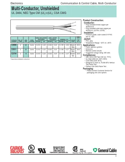
Product Construction:Conductor:• Fully annealed tinned copper perASTM B-33• Fully annealed solid bare copper perASTM B-3, (C2754, C2755)Insulation:• Premium-grade, coIor-coded S-R PVCper UL 1061Jacket:• PVC, gray• Temperature Range: –20°C to +80°CApplications:• Public address systems• Intercoms• Remote control circuits• Suggested voltage rating: 300 voltsCompliances:• NEC Article 800 Type CM (UL: 75°C)• UL Style 2464 (UL: 80°C 300V)• CSA CMG (CSA: 60°C)• Designed to meet UL 70,000 BTU VerticalTray Flame Test• Passes CSA CMG Flame TestPackaging:• Please contact Customer Service forpackaging and color options*Capacitance between conductorsProduct Construction: Conductor:• 24 AWG fully annealed stranded tinnedcopper per ASTM B-33 Insulation:• Premium-grade, coIor-coded S-R PVCper UL 1061• Color Code: See charts below Jacket:• PVC, gray• Temperature Range: –20°C to +80°C Applications:• Public address systems• Intercoms• Internal telephones• Remote control circuits• Suitable for EIA RS-232 applications • Suggested voltage rating: 300 volts Features:• Easy to terminate• Excellent electrical properties• Tinned conductors provide excellentcorrosion resistance• Assists soldering applications Compliances:• NEC Article 800 Type CM (UL: 75°C)• UL Style 2464 (UL: 80°C, 300V)• UL Style 2576 (UL: 80˚C, 150V)• CSA CMG (CSA: 60°C)• Designed to meet UL 70,000 BTU Vertical Tray Flame Test• Passes CSA CMG Flame Test Packaging:• Please contact Customer Service forpackaging and color optionsProduct Construction:Conductor:• 22 AWG fully annealed, stranded tinnedcopper per ASTM B-33Insulation:• Premium-grade, coIor-coded S-R PVCper UL 1061• Color Code: See charts belowJacket:• PVC, gray• Temperature Range: –20°C to +80˚CApplications:• Public address systems• Intercoms• Internal telephones• Remote control circuits• Suitable for EIA RS-232 applications• Suggested voltage rating: 300 voltsFeatures:• Easy to terminate• Excellent electrical properties• Tinned conductors provide excellentcorrosion resistance• Assists soldering applicationsCompliances:• NEC Article 800 Type CM (UL: 75°C)• UL Style 2464 (UL: 80°C, 300V)• UL Style 2576 (UL: 80˚C, 150V)• CSA CMG (CSA 80°C)• Designed to meet UL 70,000 BTU VerticalTray Flame Test• Passes CSA CMG Flame TestPackaging:• Please contact Customer Service forpackaging and color options†CM-CSA CMG OnlyProduct Construction:Conductor:• 20 or 18 AWG fully annealed stranded,tinned copper per ASTM B-33Insulation:• Premium-grade, coIor-coded PVC perUL 1007• Color Code: See charts belowJacket:• PVC, gray• Temperature Range: –20˚C to +80°CApplications:• Public address systems• Intercoms• Internal telephones• Remote control circuits• Suitable for EIA RS-232 applications• Suggested voltage rating: 300 voltsCompliances:• NEC Article 800 Type CM (UL: 75°C)• UL Style 2464 (UL: 80°C, 300V)• UL Style 2576 (UL: 80˚C, 150V)• CSA CMG (CSA: 60°C)• Designed to meet UL 70,000 BTU VerticalTray Flame Test• Passes CSA CMG Flame TestPackaging:• Please contact Customer Service forpackaging and color options†CM (UL) c(UL), CSA CMG OnlyProduct Construction:Conductor:• 16 thru 12 AWG fully annealed strandedtinned copper per ASTM B-33Insulation:• Premium-grade, coIor-coded PVC• Color Code: See chart belowJacket:• PVC, gray• Temperature Range: –20°C to +80°CApplications:• Public address systems• Intercoms• Internal telephones• Remote control circuits• Suitable for EIA RS-232 applications• Suggested voltage rating: 300 voltsCompliances:• NEC Article 725 Type CL3 (UL: 75°C)• NEC Article 800 Type CM (UL: 75°C)• UL Style 2464 (UL: 80°C, 300V)• UL Style 2587 (UL: 90°C, 600V)• CSA CMG (CSA: 60°C)• Designed to meet UL 70,000 BTU VerticalTray Flame Test• Passes CSA CMG Flame TestPackaging:• Please contact Customer Service forpackaging and color options†CL3, UL2587, CSA CMH OnlyProduct Construction: Conductor:• 22 thru 18 fully annealed stranded tinnedcopper per ASTM B-33Insulation:• Premium-grade, coIor-coded PVC (18 AWG), S-R PVC (22 AWG)• Color Code: See chart belowJacket:• PVC, gray• Temperature Range: –20°C to +80°C Applications:• TV antenna rotor control• Satellite actuator control• Public address systems• Suggested voltage rating: 300 volts Features:• Tinned copper conductors provide excellent corrosion resistance• Assists with soldering applications Compliances:• NEC Article 800 Type CM (UL: 75°C)• UL Style 2464 (UL: 80°C, 300V)• CSA CMG (CSA: 60°C)• Designed to meet UL 70,000 BTU VerticalTray Flame Test• Passes CSA CMG Flame Test Packaging:• Please contact Customer Service forpackaging and color options。
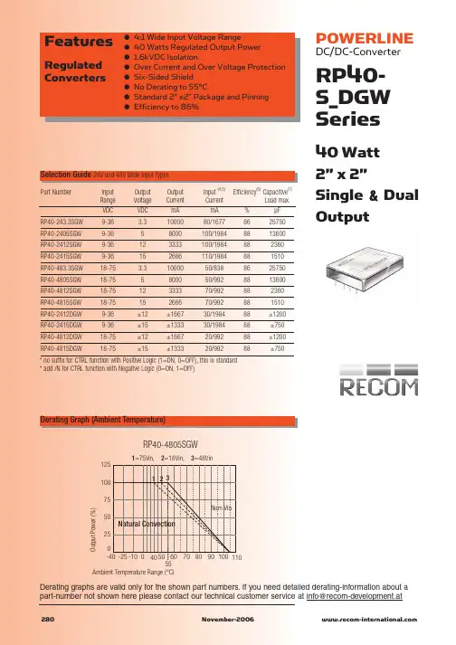

OPTEK Technology Inc.— 1645 Wallace Drive, Carrollton, Texas 75006Phone: (800) 341-4747 FAX: (972) 323– 2396 sensors@ Issue A 8/2012Page 1 of 3OPTEK reserves the right to make changes at any time in order to improve design and to supply the best product possible.Applications♦ Industrial Ethernet equipment ♦ Copper-to-fiber media conversion ♦ Intra-system fiber optic links ♦ Video surveillance systemsThe OPF2412 family is a low cost digital output fiber optic receiver. The lensed optical system keeps the receiver response consistent for all fiber sizes which makes it idea for use on fibers as small as 50/125µm. The design incorporates a monolithic photo-IC comprised of a photodetector and DC amplifier driving an open collector output Schottky transistor. The output makes the OPF2412 compatible with TTL and CMOS logic. The receiver is designed to operate from a single +5 V supply. A bypass capacitor (0.1µF ceramic) should be connected from V CC to GND of the receiver.RoHSESD Class 2PIN FUNCTION1 Not Connected2 V CC3 GND4 Not Connected5 Not Connected 7 GND6 V OUT8 Not ConnectedPins 3 & 7 are electrically connected to the header.Pins 1,4,5 & 8 are mechanically connected together.“T” suffix = Threaded ST ®packageST ®is a registered trademark of AT&T.OPTEK Technology Inc.— 1645 Wallace Drive, Carrollton, Texas 75006Phone: (800) 341-4747 FAX: (972) 323– 2396 sensors@ Issue A 8/2012Page 2 of 3OPTEK reserves the right to make changes at any time in order to improve design and to supply the best product possible.Absolute Maximum RatingsT A = 25° C unless otherwise notedStorage Temperature Range -55° C to +85° C Operating Temperature Range -40° C to +85° CLead Soldering Temperature (1) 260° CSupply Voltage -0.5 V to 7.0 VOutput Current 25 mAOutput Voltage-0.5 V to 18.0 VFan Out (TTL)5(2)Open Collector Power Dissipation 40 mWElectrical/Optical Characteristics (T A = 25°C unless otherwise noted)Notes:1. Maximum of 5 seconds with soldering iron. Duration can be extended to 10 seconds when flow soldering. RMA flux is recommended.2. 8 mA load (5 x 1.6 mA), R L = 560 Ω.SYMBOLPARAMETERMIN TYP MAX UNITS CONDITIONSI OH High Level Output Current 5 250 µA V O = 18 V, P R < -40 dBm V OL Low Level Output Voltage 0.4 0.5 V I O = 8 mA, P R > -24 dBm I CCH High Level Supply Current 3.5 6.3 mA V CC = 5.25 V, P R < -40 dBm I CCL Low Level Supply Current 6.2 10 mA V CC = 5.25 V, P R > -24 dBm P RH Peak Input Power Level, Logic HIGH0.1 µW λp = 850 nmP RL Peak Input Power Level, Logic LOW2.9 120 µW λp = 850 nm, I OL = 8 mA 4.0 100 µW -40 °C ≤ T A ≤ +85 °Ct PLHR Propagation Delay LOW to HIGH 65 ns t PHLRPropagation Delay HIGH to LOW49nsP R = -21 dBm, Data Rate = 5 MBd P R = -21 dBm, Data Rate = 5 MBdApplication CircuitOPTEK Technology Inc.— 1645 Wallace Drive, Carrollton, Texas 75006Phone: (800) 341-4747 FAX: (972) 323– 2396 sensors@ Issue A 8/2012Page 3 of 3OPTEK reserves the right to make changes at any time in order to improve design and to supply the best product possible.Mechanical DataDIMENSIONS ARE IN INCHES [MILLIMETERS]OPF2412TOPF2412。
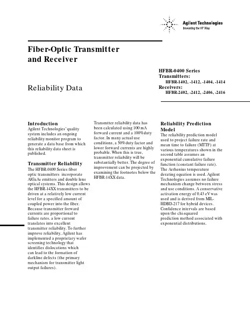
Fiber-Optic Transmitter and ReceiverReliability Data IntroductionAgilent Technologies’ quality system includes an ongoing reliability monitor program to generate a data base from which this reliability data sheet is published.Transmitter Reliability The HFBR-0400 Series fiberoptic transmitters incorporate AlGaAs emitters and double lens optical systems. This design allows the HFBR-14XX transmitters to be driven at a relatively low current level for a specified amount of coupled power into the fiber. Because transmitter forward currents are proportional to failure rates, a low current translates into excellent transmitter reliability. To further improve reliability, Agilent has implemented a proprietary wafer screening technology that identifies dislocations whichcan lead to the formation of darkline defects (the primary mechanism for transmitter light output failures).HFBR-0400 SeriesTransmitters:HFBR-1402, -1412, -1404, -1414Receivers:HFBR-2402, -2412, -2406, -2416 Transmtter reliability data hasbeen calculated using 100 mAforward current and a 100% dutyfactor. In many actual useconditions, a 50% duty factor andlower forward currents are highlyprobable. When this is true,transmitter reliability will besubstantially better. The degree ofimprovement can be projected byexamining the footnotes below theHFBR-14XX data.Reliability PredictionModelThe reliability prediction modelused to project failure rate andmean time to failure (MTTF) atvarious temperatures shown in thesecond table assumes anexponential cumulative failurefunction (constant failure rate).The Arrhenius temperaturederating equation is used. AgilentTechnologies assumes no failuremechanism change between stressand use conditions. A conservativeactivation energy of 0.43 eV wasused and is derived from MIL-HDBD-217 for hybrid devices.Confidence intervals are basedupon the chi-squaredprediction method associated withexponential distributions.Fiber-Optic TransmitterReliability Data HFBR-1402HFBR-1412HFBR-1404HFBR-1414High Temperature Operating Life TestA. Demonstrated PerformanceTest Equivalent Test Condition Samples Device Hours Failures HTOL T A = 85°C, I F = 100 mA880 units879,5003B. Failure CriteriaFailure has occurred when the unitfails catastrophically, or when thelight output power decreases 3 dB.Point Typical PerformancePerformance [1]in Time [2]in Time(90% Confidence) Ambient Junction MTTF [1]FITs [3]MTTF [2]FITs [3] Temperature (°C)Temperature (°C)(hours)(/109 Hours)(hours)(/109 Hours) 85100293,0003411131,00075968095352,0002844158,00063347590424,0002360190,00052557085514,0001947231,00043376580626,0001598281,00035606075766,0001305344,00029055570945,0001059424,000235750651,172,000854526,000190145601,462,000684657,000152340551,838,000544825,000121235502,326,0004301,044,00095830452,965,0003371,331,00075125403,810,0002631,711,000585C. Failure Rate Prediction for Random Failures (I F @ 100 mA, 100% duty cycle)Notes:1. The point MTTF (representing an esti-mate of the mean point MTTF) is the total device hours divided by either the number performance that is expected from 90% ofall samples. This confidence interval isbased on the statistics of the distribution offailure rates prior to the onset of wear out.Refer to MIL-STD-690 for details of thismethodology.Fiber-Optic Link ReceiverReliability DataHFBR-2402HFBR-2412High Temperature Operating Life TestA. Demonstrated PerformanceTest Equivalent Test Condition Samples Device Hours Failures HTOL T A = 85°C, V CC = 5.25 V3,9602,370,0001B. Failure CriteriaFailure has occurred when the unitfails catastrophically. One devicefailed to switch logic states.Point Typical PerformancePerformance [1]in Time [2]in Time(90% Confidence) Ambient Junction MTTF [1]FITs [3]MTTF [2]FITs [3] Temperature (°C)Temperature (°C)(hours)(/109 Hours)(hours)(/109 Hours) 851002,370,000421609,0001,64080952,880,000346742,0001,34075903,530,000282909,0001,09070854,350,0002291,120,00089265805,400,0001841,390,00071960756,740,0001481,730,00057655708,480,0001172,180,000458506510,700,000932,750,000362456013,600,000733,510,000284405517,500,000564,520,000221355022,700,000435,850,000170304529,700,000337,650,000130254039,200,0002510,000,00099C. Failure Rate Prediction, Receiver (V CC = 5.25 V)Notes:1. The point MTTF (representing an esti-mate of the mean point MTTF) is the total device hours divided by either the number performance that is expected from 90% ofall samples. This confidence interval isuseful life failures. Refer to MIL-STD-690 fordetails of this methodology.Fiber-Optic Link ReceiverReliability DataHFBR-2406HFBR-2416High Temperature Operating Life TestA. Demonstrated PerformanceTest Equivalent Test Condition Samples Device Hours Failures HTOL T A = 85°C, V CC = 5.25 V2,2502,250,0000B. Failure CriteriaFailure has occurred when the unitfails catastrophically.Point Typical PerformancePerformance [1]in Time [2]in Time(90% Confidence) Ambient Junction MTTF [1]FITs [3]MTTF [2]FITs [3] Temperature (°C)Temperature (°C)(hours)(/109 Hours)(hours)(/109 Hours) 851002,250,000444977,164102380952,698,5163711,171,95385375903,252,6873071,412,62770870853,941,1732541,711,63358465804,801,4322082,085,24048060755,882,7441702,554,84939155707,250,3821383,148,80831850658,991,4071113,904,927256456011,222,799894,874,010205405514,102,949716,124,846163355017,848,023567,751,315129304522,755,516449,882,616101254029,238,4093412,698,10779C. Failure Rate Prediction, Receiver (V CC = 5.25 V)Notes:1. The point MTTF (representing an esti-mate of the mean point MTTF) is the total device hours divided by either the number performance that is expected from 90% ofall samples. This confidence interval isuseful life failures. Refer to MIL-STD-690 fordetails of this methodology.HFBR-0400 Mechanical and Environmental Test Data [1]MIL-STD-883D Units Total Test Name Reference Test Conditions Tested Failed Temperature Cycle1010500 cycles from -55 to +125°C, 15 minutes20201at extremes, 5 minutes transfer. [1]HFBR-1414500 cycles from -55 to +125°C, 15 minutes20900at extremes, 5 minutes transfer.[1]HFBR-2416 85/85T A = 85°C, 85% relative humidity,21407No bias, duration = 1,000 hours. [1]HFBR-1414T A = 85°C, 85% relative humidity,22206V CC = 5 volts, Duration = 1,000 hours[1]HFBR-2416 High Temperature1008T A = 125°C800 Storage Condition B1000 hoursResistance to2015Three 1 minute immersions.200 Solvents Brush after solvent immersion.Chemical Resistance— 5 minutes in Acetone, Methanol, Freon TF200and Boiling WaterVibration Variable 2007,20 G min., 20 to 2000 Hz.200 Frequency Condition B4, 4 minute cycles each X, Y, and Z.Thermal Shock1011-55°C to +125°C, 15 cycles600Condition B 5 min. dwell / 10 sec. transferMechanical Shock2002, 5 blows each X1, X2, Y1, Y2, Z1, Z2600Condition B1500 G, 0.5 msec. pulse.Port Wear Test [2]T A = 25°C500 connectorings200Less than 1 dBm variationConnector Side T A = 25°C 1 kg side load100 Load [3]Less than 1 dBm variationPort Strength [4]T A = 25°C 6 kg-cm (5.21 inch-lbs), no port damage100 Seal-Dye Penetrant101445 psi, 10 hours200 (Zyglo)Condition D No Leakage into microelectronic cavitySolderability2003245°C300 ESD Method 3015Human body model @ 10,000 V50HFBR-1414Human body model @ 2,000 V50HFBR-2402Human body model @ 1000 V50HFBR-2416Notes: See following page.Notes:1. Devices were preconditioned with 10 second, 260°C solder dip and 20 cycles, -40°C to 85°C, temperature cycle.2. Coupled power measurements were maximized before and after stress in determining the 1 dBm variation for SMA HFBR-0400 products. HFBR-0400 ST products do not require this due to the improved coupling design.3. The Connector Side Load test was only applied to HFBR-0400 SMA products. The Connector Side Load testing required that the housing be held so to prevent the leads from yielding. The load was applied through a SMA connectored fiber optic cable, perpendicular to the port. The product family is designed to limit cable and ferrule damage due to cable loading. The support and active leads should yield before damage to the cable or connector occurs. If extreme mechanical abuse of the cable/ connector is anticipated please contact Agilent’s Application Department for suggestions about mechanical strain relief. Due to the spring loaded feature of the ST connector, HFBR-0400 ST products will experience 1 dBm coupled power variation at a side load of less than 1 kg.4. The Port Strength test was designed to gauge the concerns with hand tightening the connector to the fiber optic port. The limit is set to alevel beyond most reasonable hand fastening loading.5. Package tests are defined as stresses that indicate the environmental strength of the package. Units tested indicate the total number of devices taken from the product family. While not all part numbers have been subjected to each stress, worst case products have been included.。