麦克维尔水冷螺杆方案书(WHS)
- 格式:pdf
- 大小:6.29 MB
- 文档页数:53
水冷螺杆机说明书篇一:目录一、机组安装要求………………………………………………………………. ..……………………………..... 2 二、机组操作方法………………………………………………………………………………………………… 2 三、机组操作顺序………………………………………………………………………………………………….2 四、机组操作注意事项…………………………………………………………………………………………….3 4.1、机组安全装置????????????????????????????????????3` 4.2、附注(一):散热不良及处理方法???????????????????????????.3 4.3、附注(二):冷媒不足低压处理方法??????????????????????????.34.4、附注(三):高低压是否正常?????????????????????????????.4 4.5、附注(四):其他故障的排除方法???????????????????????????4 五、维护与保养........…………………………………………………………………………………………4六、故障排除方法.................................................. ................................................... .. (5)七、机组介绍.................................................... ................................................... .. (6)八、产品特性 ................................................ ................................................... ................................................... ..... 8 九、控制原理 ................................................ ................................................... ................................................... ..... 99.1、输入信号汇总表................................................. ................................................... ......................................9 9.2、输出信号汇总表................................................. .........................................................................................10 9.3、控制功能................................................. ................................................... .. (1)1 十、参数设置 ................................................ ................................................... ................................................... ... 13 十一、各功能使用说明................................................. ................................................... ...................................... 14 1、开机界面 ................................................ ................................................... ....................................................14 2、运行主界面 ................................................ ................................................... (14)2.1、相应参数显示 ......................................................................................... 14 2.2、机组起停开关 ................................................ ................................................... ......................................... 14 2.3、温度设定 ................................................ ................................................... . (14)2.4、查看系统状态 ................................................ ................................................... ......................................... 15 2.5、查看机组信息 ................................................ ................................................... ......................................... 15 3、修改维修者设定值 ................................................ ................................................... ............................... 163.1、时钟校................................................... . (16)3.2、基本参数 ................................................ ................................................... . (16)3.2.1设定一 ................................................ ................................................... ................................................... .. 16 3.2.2设定二 ................................................ ................................................... ................................................... .. 17 3.2.3设定三 ................................................ ................................................... ................................................... .. 17 3.2.4设定四 ................................................ ..................................................... 17 4、修改制造商设定值 ................................................ ................................................... .................................... 18 4.1、系统 ................................................ ................................................... ................................................... ...... 18 4.2、记忆 ................................................ ................................................... ................................................... ...... 18 5、故障查询 ................................................ ................................................... ....................................................19 5.1复位报警 ................................................ ................................................... ....................................................19 十二、控制模块接线图 ................................................ (20)一、安装要求:冷水机安装前请选择地基平稳,四周空旷,畅通及避免腐蚀、污染、日晒、雨淋,方便安装维修之场所。


Installation & Operation manualScrew Type Water Cooled ChillerNanjing Lidesheng Machinery CO.丄TD.ContentPart 1 Installation and maintenanceIntroduction (2)Schematic drawing for service clearance (3)Schematic drawing for hoisting (4)Setup and maintenanceeeeeeeeeeeeeeeeeeeee 5 Part 2 Controlling and handling Introductioneeeeeeeeeeeeeeeeeeeeeeee 12Part 1 Installation and maintenanceIntroductionMENERGY MSSH serial Water-cooled Screw-type Chiller, which is concisely designed, applies the advanced semi-enclosed dual-screw compressor and the high-effective heat exchange tube with the most updated technologies, and can be controlled through the advanced microcomputer. This product has advantagesof stable system, low oscillation, high reliability and high effectiveness on energy saving. MENERGY original anti-reversal program for the compressor can strengthen the running reliability of the chiller. This product has more than twenty types for being extensively applied in many comfortable or technical situations by the customer.Before the chiller is started up, all the related personnel in charge of setup, startup, operation and maintenance should carefully read through this manual so as to know all the precautions onsite.Schematic drawing for service clearance Sin gle-head:Dual-head:____________ r————Schematic drawing for hoisting Sin gle-head:Dual-head:Attention: Use protecting barwhe n hoist ingSetup and maintenanceSetup and maintenance of the chiller should only be carried out by a qualified person whohas bee n trained professi on ally, and is familiar with local sta ndards and rules and haspractical operational experienee. The trial running of the chiller must be carried out by theprofessional service supplier to ensure the quality of the chiller.Check before acceptanceAfter the device has arrived, check if all the items listed in the delivery order arecomplete, and any part damaged duri ng tran sportati on should be in formed to the forwardi ngage nt with writte n form for claim. Before setup, check if the local supply voltage, frequencyand so on are complying with the chiller. MENERGY will bear no liability for any damage afterthe device has bee n accepted.HoistingHeavy-duty ropes or chains should be used for hoisting through the hoisting holes of thechiller, and the con trol cab in et a nd other parts of the chiller should be protected fromdamage whe n hoisti ng (The schematic draw ing for hoist ing in troduced above should bereferred to).Environmental requirementThe chiller is suitable to be used in the en vir onment that the surro unding temperatureis -15 °C above and the relative humidity is<95%, and the ground for placeme nt should be horiz on tal and with eno ugh solidity or rein forceme nt measures should be take n (The requirementsin the schematic drawings of ground base and service clearanee for the chiller should bereferred to).Water quality requirementAs the compositi on of local water is complicated, the water quality should be check whe nsome un com mon water (such as in dustrial waste water, ground water, etc.) is used. If thewater quality does not satisfy the requirement for the water used in air-conditioning, the watershould be treated accordi ng to the Specificati on for Desig n of In dustrial Re-circulat ingCooli ng Water Treatme nt or other related sta ndards.c「mg/L v 200 v 200SO42-mg/L v 200 v 200SiO2 mg/L v 50 v 50NH4 +mg/L v 1.0 v 1.0S2-mg/L Not allowed Not allowedFree Chlori ne mg/L v 1.0 v 1.0Oil mg/L v 5 v 5Water pipesBoth outlet and inlet of the chiller should be equipped with a stop valve, a thermometer and a pressure gauge for routi ne check and maintenance of the water system; and both outlet and inlet of the water pump should be equipped with a stra iner to preve nt impurities from going into the pump or the vessel; before insulating the heat of the water pipe, the seali ng of the pipeli ne should be checked whe n the water is to go into the chiller; all the pipeli nes conn ected with the chiller should be equipped with vibratio n dampers and flow con trollers (such as water flow valves, water pressure differe nee switch, etc.) as per the requirement; when a device for contamination draining is to be mounted to the water system of the air-conditioning engineering, it should be avoided from the pipelines of the outlet and inlet of the chiller, or the normal operation of the chiller would be disturbed. Schematic drawing for the external water pipeline systemPipeline design Installation Notesa)Pipe works must avoid any unnecessary bends and offset(up and down).b)Install gate valve for every joint for service and maintenance.c)Air vent must be installed at the highest position.Open the air vent to realease the airsafety valveOutlet Of TheColli ng Tower1 ----- 1 J—1 Water Valve------------------- II——I V itW1 i| 1—thermometerLPressure guage Flow Switch5Inlet Of TheColli ng TowerWater filter pumpWater ValvePressure guage Pressure guage_______ icon trol valveFlexible joi ntsFlexible joi ntsDrai n valvePressure guagethermometertrapped in the water system.d)Water pump must install at water return linee)At the lowest point of the pipe work,install a gate valve drain out water.f)At the highest point of the pipe work,install a manual or automatic air vent.g)Install strainer before water entering to the water pump.h)Flush lot of clean water to remove foreign material before unit start up.i)Pressure gauge and thermometer must be installed at visible and accessible location. Check before starting upWater circuit partCheck all the pipelines of the water system to ensure that the evaporator and the condenser are correctly connected and the water flow direction is correct. Check if the inlet pipe and the outlet pipe of the heat exchanger mentioned above are well connected, and then open all the water valves and start up the corresponded water pump to wash the pipes so as to ensure the water system is clean and check if there is any leakage at the pipes and joints. Discharge the air in the water circuit of the evaporator and the condenser, and the water circuit should be keep clean away from rust. Check the resistance loss at the water side of the evaporator and the condenseragainst the water volume. Check if the temperature transducers are correctly connected. Electric circuit partCut off the main isolating switch and then check all the startup circuits and control circuits of the control cabinet to ensure all the switches are in off position. Check the power supply to the chiller and the voltage fluctuation range should be within 10% of the±rated voltage shown on the nameplate of the compressor, and the unbalance of the phase voltage should be within 2%. Check if there is enough power supply capacity to ensure the startup andfull load running of the chiller. Check if all the electric wires and fuses have the matched specification with the running of the chiller, and finish all the interlock control circuits according to the related electric control drawing. Check and ensure all the ancillary equipments and control equipments for air-conditioning are in normal operation and have enoughrefrigerating capacity to satisfy the running requirement of the chiller at the first operation. Chiller partMake sure that the engine oil heater of the compressor has been electrified for 24 hours, and examine the oil level through the inspecting mirror of the oil separator,and refill oil if the oil level can not be seen. Fully open the manual stop valve on the sparging pipe and remove the seal bonnet away, and fully open the suction and discharge stop valve and then counterclockwise turn it back for 1/2 circle, and then fully open the liquid supply stop valve and start up the ancillary equipments, the condensed water pump and the refrigerated water pump, and finally check if all the safety control equipments are in original status and if thesettings are correct. See <Table 1> below for the related items for checking.Safety equipmentsThe chiller is equipped with safety protective devices to ensure safe running, and if one of the safety protective devices is in operation, an error indicator will turn on, and the corresponded function will stop while the other functions will be still normal. It isrecomme nded to stop the chiller for troubleshoot ing to avoid from more serious accide nt only if any part becomes abnormal. See vTable 2> for the detailed series of the safety protective devices of the chiller.Recommended running rangeRecommended maintenance periodsTroubleshooting for the Screw-type ChillerPart 2 Controlling and handlingSECTION 1 INTRODUCTIONand technician, if act against this rule, FRIMEC will not respond for any unit damage and people injured.Operati ng Con diti onIn stall the equipme nt below 2000 meters altitude.Ambient Temperature: Max. 45C , Min. -20 °C .Relative Humidity: Less than 85%.No con ductive dust and corrosive gas which may destroy metal and in sulati on.Fun cti on Feature of Con trollerSCHNEIDER PLC is the controller for chiller. The unit can operate according with program automatically.Easy OperationAs the leaving water temperature is setting, the operator press start key then the unit will be operating automatically; and it will stop when press stop key. The intervention from operator is not n eeded duri ng en tire process.Rotating test and manual test can be utilized in order to facilitate regulation and repairing.Data SupervisionWhe n the unit is power on, the unit will check digital and an alog in put automatically and the unit will adjust the capacity based on the water temperaturein time. The data collecting is very fast and its accuracy is high, it will reflect the actual fact.TroubleshootingTrouble will be solved immediately via the program and it will make pre-alarm or alarm at the same time. The unit will stop running when the unit occur severe trouble in order to avoid further damage.Safe and Easy to ManageThe protection of setting password is used in order to protect safety and performance of the unit. You can give different authority according to your different requirement, so that you will not be worried about the abnormal damage of unit as the operator or other person exceed their authority. In other words, the unit is safety and easy to manage.。
水冷螺杆机组施工方案及流程下载温馨提示:该文档是我店铺精心编制而成,希望大家下载以后,能够帮助大家解决实际的问题。
文档下载后可定制随意修改,请根据实际需要进行相应的调整和使用,谢谢!并且,本店铺为大家提供各种各样类型的实用资料,如教育随笔、日记赏析、句子摘抄、古诗大全、经典美文、话题作文、工作总结、词语解析、文案摘录、其他资料等等,如想了解不同资料格式和写法,敬请关注!Download tips: This document is carefully compiled by theeditor. I hope that after you download them,they can help yousolve practical problems. The document can be customized andmodified after downloading,please adjust and use it according toactual needs, thank you!In addition, our shop provides you with various types ofpractical materials,such as educational essays, diaryappreciation,sentence excerpts,ancient poems,classic articles,topic composition,work summary,word parsing,copy excerpts,other materials and so on,want to know different data formats andwriting methods,please pay attention!水冷螺杆机组施工方案及流程水冷螺杆机组施工方案及流程主要包括以下几个关键阶段:一、施工准备1.1 检查机组电源接线、电压等是否符合要求。


麦克维尔中央空调、地暖方案(中央空调·地暖·水处理·门窗·木门·墙板·新风·除尘·)项目名称:XXXXXX X目录XXXXXX有限公司2016年XX月XX日一、公司简介1-1慈溪商豪贸易有限公司简介是一家集销售、安装和维修各类中央空调的专业性中央空调公司。
XXXXXXXXXXXX公司经营大金、麦克维尔、等知名品牌的中央空调产品,在家居方面,还销售地热采暖系统、中央新风、中央热水、中央净水和软水等家居集成系统。
公司经营品类有家用(户式)中央空调、商用中央空调、大型中央空调等系统。
包括VRV变频多联式中央空调等。
公司有专业的设计师、工程师和安装维修技术工人队伍,并经过了大金公司的专业测试和专业认证。
公司以完善的售前、售后服务为后盾,以“质量和诚信”的经营理念,致力于人工环境事业的美化和推广。
我们是您的“中央空调专家”,我们以诚信的素养和专家的品质,加上我们过硬的工程安装质量为您打造一个优质实惠的五星级家居办公环境。
二、产品简介2-1麦克维尔中央空调简介自1872年起,麦克维尔便开始在美国设计制造蒸汽机。
通过130多年的发展和兼并,麦克维尔锐意进取,不断创新,拥有世界空调发展史上的诸多第一。
今天,麦克维尔旗下包括了"McQuay Air Conditioning"、"HermanNelson"、"Remington"、"AAF"、" J&E Hall"等知名品牌。
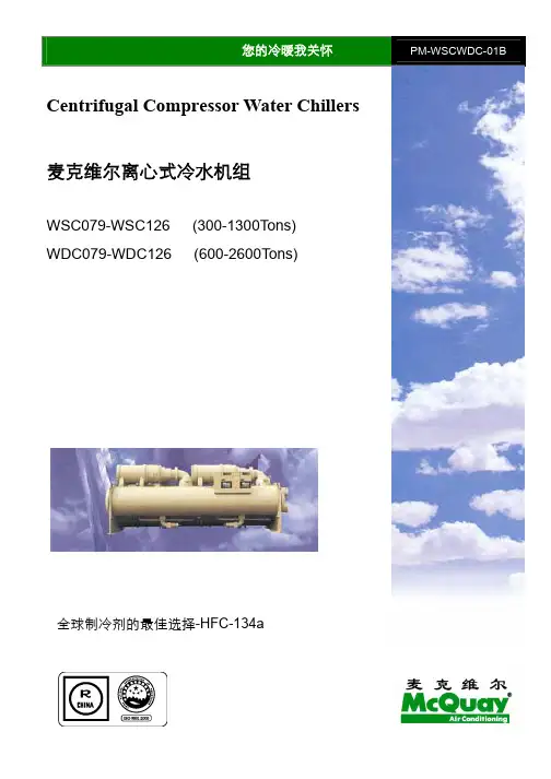
麦克维尔于1982年全面收购了美国国际西屋集团(WESTING HOUSE S.A)的中央空调部;1987年收购了欧洲最悠久的空调公司WESPER公司;1988年收购了美国著名的空气净化设备公司AAF公司,并成立了AAF--McQuay集团;1995年英国历史悠久的空调、制冷公司J&E Hall的加盟更加壮大了麦克维尔的力量,自此麦克维尔的产品已覆盖了工业用、商业用及家用暖通空调设备、空气过滤器及冷冻、冷藏用机组的整个范围,主要产品包括:水冷离心式、水冷螺杆式和水冷活塞式冷水机组,吸收式冷水机组,风冷螺杆式、活塞式、涡旋式冷水机组,风源和水源热泵,风机盘管,空气处理机,屋顶式及商用整体空调机,各类型的商用及家用单冷/冷暖分体式空调机和水冷柜机等。
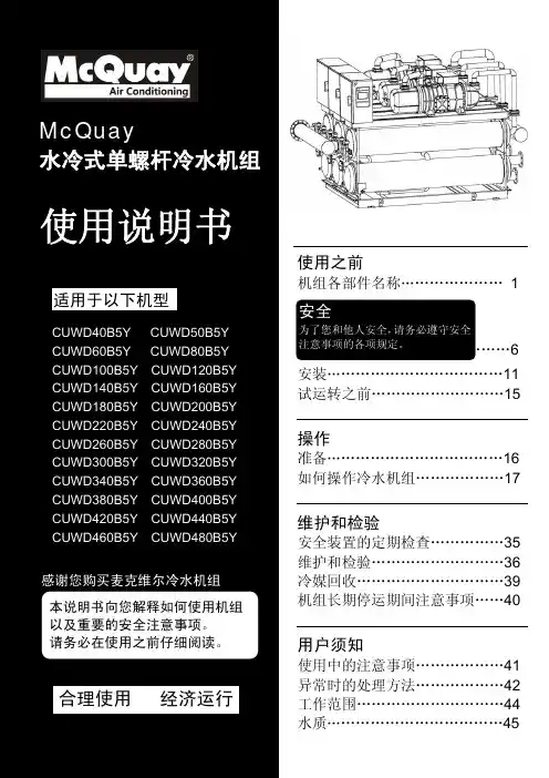
麦克维尔单螺杆冷水机组运行操作培训手册1目录1.麦克维尔单螺杆冷水机组日常操作流程 (3)2.触模式显示屏操作简介 (4)3.麦克维尔单螺杆冷水机组日常维护 (5)4.麦克维尔单螺杆冷水机组常见故障分析 (6)5.麦克维尔单螺杆冷水机组系统流程图 (7)6.麦克维尔单螺杆冷水机组技术参数 (8)麦克维尔单螺杆冷水机组日常操作流程z日常开机1.启动冷冻水水泵和冷凝水泵。
2.机组显示屏必须通电24小时或压缩机油槽温度不低于40℃。
3.检查机组的排气截止阀,吸气截止阀,供液截止阀,喷液截止阀是否打开:4.点击“主画面”,点击“启动”按钮,运行(绿色)指示灯亮,机组倒计时完毕机组按顺序启动。
5.机组启动后听压缩机有无发出异常噪音。
6.当排气压力1.4Mpa或冷凝器进水温度28℃时,启动冷却塔风扇。
7.观察蒸发器出水温度显示是否正常。
z日常停机1.在显示屏的“主画面”点击“停止”按钮,运行指示灯灭,机组慢慢减载直至停机。
2.停止冷凝水水泵与冷却塔风扇。
3.待蒸发器出水温度≤15℃后停止冷冻水水泵。
z长期停机如长时间停机需断开主电源,当环境温度≥5℃时,必须将蒸发器与冷凝器内的水放干净,避免冻坏机组。
z紧急停机当机组出现紧急故障(如压缩机噪音异常、控制线路短路等)需紧急停机时,按机组控制面板上的红色急停开关。
麦克维尔单螺杆冷水机组触摸式显示屏操作简介麦克维尔单螺杆冷水机组是单色触摸式显示屏,具有中文显示、显示亮度可调等功能使用方便、操作简单。
在使用时注意表面清洁,勿用硬物将表面划伤。
z触摸式显示屏的操作1、触摸式显示屏上电后,显示屏将显示系统(英文)菜单:A、(Download)下载程序B、(Uploap)上载程序C、(Copy)拷贝程序D、(Contrast)亮度调节E、(Run)进入运行画面2、点击“Run”将显示麦克维尔单螺杆冷水机组主画面,点击“主画面”后显示:设定温度、出水温度、总能量、等待时间,在屏幕下方有三个按键分别为:启动、停止、菜单。
麦克维尔MHS单螺杆风冷热泵机组技术规范书McQuay®单螺杆风冷热泵机组MHS100.1 FST2每套供货范围包括:-全中文微电脑控制器;-风冷整体式冷凝盘管;-机翼型高效螺旋风机;-高效壳管式水换热器;-制冷剂及润滑油;-弹簧减振器;-水流量开关;-使用说明书;-电路图;-合格证;-保修单;品牌:McQuay®“麦克维尔”产地:中国深圳型式:风冷单螺杆式热泵机组型号:MHS100.1 FST2数量:台冷媒:HCFC--22每台制冷量:kW 360每台制热量:kW 378制冷输入功率:kW 118制热输入功率:kW 122制冷循环数目:NO. 1运行重量:kg 4260运输重量:kg 4110外型尺寸长度:mm 4100宽度:mm 2260高度:mm 2360压缩机型式:半封闭单螺杆式型号:HSS 系列数量:NO. 1动力传送:电机直驱能量调节级数:NO. 无级(0,25~100%)控制器- 显示:全中文- 显示屏:液晶显示屏- 显示字数:NO./界面4×20(英文字母)或2×10(汉字)- 内存:static RAM 256Kbyte;FLASH MEMORY 2MByte- 类型:PLC可编程- 软件等级: A水侧换热器- 式样:整体干式壳管式- 制冷水流量:m3/h 62- 制热水流量:m3/h 65- 进水温:℃12.0- 出水温:℃7.0- 污垢系数:m2℃/kw 0.018- 工作压力:MPa 1.6- 管道材料:高效螺纹铜管- 接水管口径:inch 5- 接管方式:快速接头风侧换热器- 结构:倒M型- 型式:风冷式- 管道材料:内肋无缝铜管- 翅片材料:开窗式铝片- 加工工艺:机械胀管- 承压:MPa 3.3风机- 型式:机翼型- 扇叶:高效螺旋式叶片- 电机:内转子- 驱动方式:直驱式- 数量:NO. 8- 电机功率:kW/台 2.0- 机组总风量:m3/h 176000电源- 标准电源:V/ Ph /Hz 380/3 ~/50- 电压允许偏差:% ±10- 压缩机熔断电流:A 315- 风机额定电流:A 32- 整机额定电流:A 215。