PMS5XXXS颗粒物传感器中文说明书V1.2
- 格式:pdf
- 大小:618.70 KB
- 文档页数:7

1、Generator protection. 发电机保护The generators are protected against the various faults by protection devices whichare located in their respective generator panels and on the generator’s ACB itself.发电机的保护由相应发电机屏内保护设备与发电机主开关实现。
1.1.MICROLOGIC5.0A control module MICROLOGIC5.0A 控制模块This device which is located on the individual generator ACB providesgenerator protection against the following:该装置在发电机主开关上,为发电机提供以下保护:♦Over-current (Long Time)过电流(长延时):When the prevailing load current of the generator exceed 125% of the protectiondevice’s setting and maintain for a duration of 15~30s, it will cause the respectivegenerator ACB to trip.当发电机电流超过额定电流150%时, 延时15~30s 发电机主开关跳闸。
♦Short-circuit current (Short Time) 过电流(短延时)When short-circuit current exceed 2.5 times of the protection device setting andmaintain for duration of 400 msec, it will cause the respective generator’s ACB totrip.当发电机电流超过额定电流250%时, 延时400 ms, 发电机主开关跳闸。
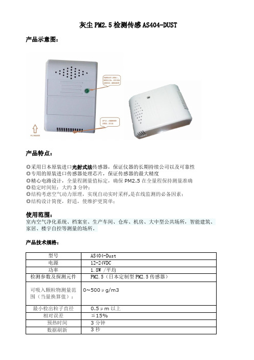
灰尘PM2.5检测传感AS404-DUST产品示意图:产品特点:◎采用日本原装进口光射式法传感器,保证仪器的长期持续公司以及可靠性◎专用的原装进口传感器处理芯片,保证传感器的最大精度◎精心电路设计,全量程测量值标定,确保PM2.5在全量程保持测量准确◎稳定时间短:大约3分钟;◎结构考虑空气动力原理,实现自动实时采样,是在线监测的必备因素;◎结构设计简便,舒适,使维护更简单;使用范围:室内空气净化系统、档案室、生产车间、仓库、机房、大中型公共场所,智能建筑、家居、楼宇自控等测量的场所。
产品技术规格:型号AS404-Dust电源12-24VDC功率 1.8W /平均检测参数及探测元件PM2.5(日本定制型PM2.5传感器)0~500μg/m3可吸入颗粒物测量范围(当量换算值):最小检出粒子直径0.5μm以上相对误差≦15%预热时间3分钟数据刷新3秒分辨率1ug/m3稳定性使用周期内小于2%反应时间小于3分钟通讯接口Modbus RS485/4-20ma可选通讯速率9600,14400,19200(默认),28800,38400 bps(可设定),15KV防静电保护,3位独立地址,最大网络节点数64(可选)操作环境0~50℃(32~122℉); 20~95%RH壳体材料塑料外壳防护等级IP20存储条件-40~70℃(-40~158℉)重量/尺寸38G / 100×68x36mm电气连接:输入:红:12-24VDC 黑:GND输出:黄:RX 白:TX安装方式:壁挂式/固定式注意:使用中请严格注意电源线和信号线不要碰一起,以免造成电路烧毁!1、通讯(Modbus Rtu)串口设置(RS485/ttl):波特率9600,无校验,8数据位,1停止位。
2、万能通讯命令16进制:00 03 00 00 00 01 85 DB (不清楚设备地址可用此找回)地址位命令字数据长度数据CRC1601 03 02 00 81 78 2424、寄存器描述(支持03和06命令字)寄存器40001 存储PM2.5浓度值(mg/m3)400024000340013 PM2.5微调参数(值越小读数越小10~120取值范围)微调后请过3分钟再观察数据40018 寄存器锁定位(修改其它参数前需先将此位改为十进制24)断电自动锁定40019 设备型号(可根据需求定制,也可自行修改)40020 串口通讯地址(默认为1)5、接线说明:红黑(电源9~24V)白:A (485)黄:B (485)6、指示灯说明:程序正常运行指示灯会亮,串口通讯正常指示灯会闪烁7、传感器工作时需垂直竖立,不得平铺,倒立!并避免阳光直射,强风对流等环境!8、测试时,可点燃一只香烟,待进气口探测烟气后观察传感器的输出反应!如遇大颗粒环境或超量程检测后,传感器将自动开启保护模式(停止监测),以便保护传感器核心不被严重污染,此时需将传感器放置在空气流动环境,重新预热!CRC16校验计算函数(请确认单片机大端编程还是小端)/******************函数CRC_16()*********大端返回short int参数data【】数组、len数组长度例子:datax【8】={01, 03, 00, 00, 00, 01, 00, 00}16进制unsigned short int x=CRC_16(datax,6);得到x=0x840a;***************************************************/unsigned short int CRC_16(unsigned char *data,int len){unsigned char *buf;unsigned short int * CRC;unsigned short int crch,crcl;short int i;short int j;char err;buf= & data[len];CRC=(unsigned short int *)buf;buf[0]=0xff;buf[1]=0xff;for(i=0;i<len;i++){buf[0]=buf[0]^data[i];for(j=0;j<8;j++){err=buf[0]&1;*CRC=*CRC/2;if(err) *CRC=*CRC^0xa001;}}crch=*CRC>>8;crcl=*CRC<<8;*CRC=crch+crcl;return(*CRC);}/******************函数CRC_16()*********小端返回short int参数data【】数组、len数组长度例子:datax【8】={01, 03, 00, 00, 00, 01, 00, 00}16进制unsigned short int x=CRC_16(datax,6);得到x=0x840a;***************************************************/unsigned short int CRC_16(unsigned char *data,int len){unsigned char *buf;unsigned short int * CRC;unsigned short int crch,crcl;uchar p;uchar j;char err;buf= & data[len];CRC=(unsigned short int *)buf;buf[0]=0xff;//lsbbuf[1]=0xff;//msbfor(p=0;p<len;p++){buf[1]=buf[1]^data[p];for(j=0;j<8;j++){err=buf[1]&1;4*CRC=*CRC/2;if(err) *CRC=*CRC^0xa001;}}crch=*CRC>>8;crcl=*CRC<<8;*CRC=crch+crcl;return(*CRC);}*以上文档中提到的文字及图片阿尔森保留一切解释权说明书并不针对某一特定机型,书中所提到的某些部件、色差有可能与您买的型号稍有差异。

粉尘传感器(型号:ZPH02)使用说明书版本号:1.2实施日期:2018-05-16郑州炜盛电子科技有限公司Zhengzhou Winsen Electronic Technology Co.,Ltd声明本说明书版权属郑州炜盛电子科技有限公司(以下称本公司)所有,未经书面许可,本说明书任何部分不得复制、翻译、存储于数据库或检索系统内,也不可以电子、翻拍、录音等任何手段进行传播。
感谢您使用炜盛科技的系列产品。
为使您更好地使用本公司产品,减少因使用不当造成的产品故障,使用前请务必仔细阅读本说明书并按照所建议的使用方法进行使用。
如果您不依照本说明书使用或擅自去除、拆解、更换传感器内部组件,本公司不承担由此造成的任何损失。
您所购买产品的颜色、款式及尺寸以实物为准。
本公司秉承科技进步的理念,不断致力于产品改进和技术创新。
因此,本公司保留任何产品改进而不预先通知的权力。
使用本说明书时,请确认其属于有效版本。
同时,本公司鼓励使用者根据其使用情况,探讨本产品更优化的使用方法。
请妥善保管本说明书,以便在您日后需要时能及时查阅并获得帮助。
郑州炜盛电子科技有限公司ZPH02粉尘传感器产品描述本传感器整合红外PM2.5检测技术,采用粒子计数原理对环境中PM2.5进行检测。
可灵敏检测直径1μm以上灰尘颗粒物。
传感器在出厂前经过老化、调试、标定、校准,具有良好的一致性和较好的灵敏度。
传感器特点长期稳定性好 灵敏度高 接口输出方式丰富一致性好易安装、维护主要应用空气净化器 新风系统 空气清新机空调系统便携仪表烟雾报警器技术指标表1产品型号ZPH02工作电压范围5±0.2V(DC)输出方式低电平时间比率%(推荐时间30s)输出信号电压5±0.2V检测能力检出粉尘最小粒子1μm预热时间≤1min(整机热稳定时间)工作电流≤90mA湿度范围储存环境≤95%RH 工作环境≤95%RH温度范围储存环境-30℃~50℃工作环境0℃~50℃外形尺寸(L×W×H)59.5×44.5×20mm 物理接口EH2.54-5P端子插座试验分类NO.试验项目条件及要求结果1规格尺寸1、尺寸规格尺寸确认电气特性确认内部电阻间距确认符合图纸要求n=10OK2冷热冲击(冷热冲击箱)1冷热冲击1-40℃30m←→10s内←→80℃30m为1个循环,10个循环①外观无显着异常②电气参数满足要求满足:下限*0.7~上限*1.3n=10OK3冷热冲击(冷热冲击箱)2冷热冲击2-25℃1H←→70℃1H为1个循环,100个循环①外观无显着异常②电气参数满足要求满足:下限*0.7~上限*1.3n=10OK4高温高湿(高温湿箱)1#高温高湿放置60±5℃,90±5%RH,72H放置①外观无显着异常②电气参数满足要求满足:下限*0.7~上限*1.3n=10高温负荷(THB)60℃±5℃,90±5%RHDC5V72H连续通电①外观无显着异常②电气参数满足要求满足:下限*0.7~上限*1.3n=10OK5低温(高低温箱)2#低温放置-30℃,500H测试一次,1000H测试一次。

1PM2.5/PM10浓度二合一有线变送器产品使用手册V1.2版1概述LT-CG-S/D-001-A7020-2-12PM2.5/PM10传感器采用符合国际标准的激光散射原理,内嵌式设计、开发,操作简单,使用方便,模块内部提供激光光源及光电接收装置,激光照射在空气悬浮物颗粒上产生散射,同时在某一角度接收散射光,得到散射光强随时间变化曲线,基于米氏理论算法,得出颗粒物的等效粒径及单位体积内不同粒径颗粒物的数量(PCS/0.1L )、重量(ug/L )两种测量结果,并通过串口分别输出PM1.0、PM2.5、PM10三档不同量程的颗粒物体积浓度或质量浓度数据。
采用DC 6~24V 电源供电,可选配液晶屏实时显示采集参数,还可选配1路继电器报警输出。
作为现场采集从站,标准MODBUS-RTU 通信协议RS485数字信号输出,适合远距离组网传输,完全兼容组态王等多种上位机组态软件,易与第三方设备配套。
产品广泛应用于智能家居,智能商厦,智能养殖,智能交通,气象站等环境测量领域。
2特点1、激光原理测量,信号无衰减,零错误报警率、计数更精确,产品寿命长2、传感器探头可准确测量0.3~10um 直径颗粒,测量范围宽、线性度好3、传感器通过串口分别输出0.3~1um、1~2.5um、2.5~10um 三档不同量程的颗粒物浓度信号,统计更精确、合理4、变送器可选配液晶屏、继电器报警输出等功能5、激光测量PM2.5比IRED 测量方式更专业,1um、2.5um、10um 三档量程更符合国内外权威机构认可3外形规格4产品资料规格型号:LT-CG-S/T-001-A7021-2-12-V1.2(包含液晶屏)LT-CG-S/T-001-A7020-2-12-V1.2(不含液晶屏)LT-CG-S/T-001-A7021-2-DO-12-V1.2(包含液晶屏、1路报警)PM2.5/PM10测量原理:激光散射法2PM2.5/PM10测量直径:0.3~1、1~2.5、2.5~10umPM2.5测量范围:0~999ug/m3,可选0~1999ug/m3(质量浓度)PM10测量范围:0~999ug/m3,可选0~1999ug/m3(质量浓度)体积颗粒物浓度:PCS/0.1L(每0.1升多少颗粒)最小颗粒直径:0.3um精度:<±10%分辨率:0.1ug/m3或1PCS/0.1L重复性:<10%输出信号:瞬时PM1.0、PM2.5、PM10浓度测量稳定时间:5秒响应时间:<10秒工作环境:-20~55度,5~95%RH(无凝结)存储环境:-25~70度供电电压:DC7~24V显示方式:LCD液晶屏(选项)液晶屏规格:08022行显示,每行8个字符报警、控制输出(选配):1路继电器,触点容量(阻性):3A/AC220V、DC24V通信接口:RS485通信速率:2400、4800、9600、19200、38400、115200。

PMS200系列颗粒物传感器使用说明书1.产品简介PMS200系列是基于激光散射原理的颗粒物浓度测量传感器。
它使用稳定性极好的激光LED和高灵敏度的探测器,对颗粒物的个数和粒径分布进行精确测量,输出精确的颗粒物浓度值。
它体积小巧、支持数字通讯,便于集成到其他产品中。
PMS200是常规颗粒物传感器,PMS200T是颗粒物和温湿度一体式传感器。
2.产品特点●激光散射实现精准测量●零误报率●实时响应●最小分辨粒径0.3微米3.工作原理PMS200系列颗粒物传感器采用激光散射原理,即令激光照射在空气中的悬浮颗粒物上产生散射,同时在某一特定角度收集散射光,得到散射光强随时间变化的曲线,再利用基于米氏(MIE)理论的算法,得出颗粒物的等效粒径及单位体积内不同粒径的颗粒物浓度。
传感器工作原理如图1所示。
图1 PMS200系列颗粒物传感器工作原理示意图4.技术指标5.输出接口PMS200输出颗粒物的质量浓度,PMS200T输出颗粒物的质量浓度和温湿度。
(1)接口描述数据接口:其中2pin为串行数据通讯接口,采用通用异步收发协议(UART);所有电平均为3.3VTTL电平。
(2)接口管脚定义说明图2 PMS200颗粒物传感器的接口管脚定义注:SET=1,表示模块工作在连续采样方式,模块在每一次采样结束后主动上传采样数据,数据更新时间小于2s。
6.外形尺寸单位:毫米(mm)图3 PMS200颗粒物传感器外形尺寸示意图默认波特率:9600bps 校验位:无停止位:1位默认波特率:9600bps 校验位:无停止位:1位。
扬子江药业集团有限公司洁净室颗粒及微生物监测系统技术标美国粒子监测系统有限公司(无锡旭野科技有限公司)目录1. 概述2. 公司简介3. 方案描述系统描述颗粒传感器技术说明3.3 报警系统技术说明制药专用软件说明4. 项目管理及服务范围5. 质量保证及售后服务6. 部分国内外业绩表7. 设备清单8. 技术偏离表1. 概述本方案是Particle Measuring System (美国粒子监测系统公司)针对扬子江药业集团有限公司洁净室项目所制定。
其中包括对整个方案所需的硬件和软件的技术参数及性能描述。
同时,方案还包括PMS公司对该项目管理,对系统的安装,调试,开车和验收提供的相关服务和支持,以及对所提供的相关认证文件的描述。
该测量系统的目的是记录生产线中关键区域空气中颗粒存在的状况。
它可以对所监测环境空气中颗粒的粒径和数量分布进行自动的,连续的监测和记录,同时产生报表。
当监测环境中的颗粒状态超过设定值时,该系统能自动激发声光报警,通知相关人员进行处理,从而帮助确保所监测的关键环境中的颗粒状况处于正常状态,以保证生产的顺利进行。
PMS公司所提供的技术方案是根据CGMP的相关标准所制定的,符合FDA 和EU对于CGMP的要求和规范。
该方案主要包括以下几部分:•Rnet 510 颗粒传感器•真空系统(含双泵并互为补充)•警报系统•制药专用监控软件,实时记录•项目管理,安装调试,系统测试服务•认证文件该方案是包括整个系统的设计,施工,调试,认证的交钥匙工程。
将由PMS公司指定的项目经理负责监督完成。
2. PMS公司简介美国粒子监测系统公司,简称PMS公司,是由Bobert Knollenberg 博士于1972年成立于美国的科罗拉多州宝德市,到今天为止,已有36年的历史。
公司从成立到现在,一直在微污染监测领域从事设计,生产和服务。
所生产的不同种类的颗粒技术器可以用来测量包括空气,水,化学品及其他气体中的颗粒状态,在制药,半导体,航空航天等需要无尘生产的行业中得到的普遍的应用。
说明书产品名: 粉尘传感器型号: SM-PWM-01CSM-PWM-01CSMART dust sensor for home appliance■ 概述SM-PWM-01C 是一款利用光学方法检测空气中粉尘浓度的传感器。
在传感器中一个IR LED 和一个图像传感器光轴相交,当带粉尘的气流通过交叉区域,产生反射光。
图像传感器检测到粉尘反射的IR LED 光线,根据输出的强弱判断粉尘的浓度。
此款粉尘传感器能检测像香烟颗粒大小的颗粒物与室内灰尘等大颗粒,通过输出PWM 脉冲信号宽度区分。
■ 产品特征紧凑外形,质量轻(W59x H45x D20 mm, ~35g)PWM (pulse width modulation) 输出 (低脉冲输出)能够区分室内香烟等小颗粒和灰尘(花粉,尘埃,毛屑)等大颗粒 低脉冲的宽度比例表示颗粒物大小和浓度 粉尘传感器通过加热电阻形成恒定的气流 无铅和ROHS 认证■ 应用领域空气中的粉尘监测,室内空气质量监控 空气过滤器,空气净化机,空调室外灰尘监测(需要客户特殊的外形结构设计) 烟雾报警■ 检测原理图P1: small particle (1~2㎛), P2: large particle (3 ~10㎛)☞ SM-PWM-01C 粉尘传感器不可用于计数,不能测量粉尘数量级,颗粒大小仅做参考■ 电气特性绝对最大额定参数工作电压和信号输出*1粉尘传感器加热电阻稳定时间30s*2.输入阻抗200㏀, 上拉电阻 10㏀,推荐30sec 移动平均时间计算浓度Dust, Cigarette Smoke Amplifier CircuitRXRegulatorStabilization of power line ripple, noiseResisterMICOMSensitivity adjustmentR-HeaterDust flow IR LEDGND Vcc (+5 V) Signal Output (P1) Signal Output (P2) 13 54 2接口标准连接头(SM-PWM-01C)客户可定制接头(model: SM-PWM-01C-J)管脚定义光电特性*1灵敏度定义为在30 sec内,粉尘浓度变化100µg/m³,所确定的低脉冲宽度变化的总量。
DSENSOR数字式通用颗粒物浓度传感器PMSA003数据手册主要特性◆激光散射原理实现精准测量◆零错误报警率◆实时响应并支持连续采集◆最小分辨粒径0.3μm◆全新专利结构,六面全方位屏蔽,抗干扰性能更强◆进出风口方向可选,适用范围广,用户无需再进行风道设计◆超薄超小设计,仅有12毫米,适用于便携式、穿戴式设备概述PMSA003是一款基于激光散射原理的数字式通用颗粒物浓度传感器,可连续采集并计算单位体积内空气中不同粒径的悬浮颗粒物个数,即颗粒物浓度分布,进而换算成为质量浓度,并以通用数字接口形式输出。
本传感器可嵌入各种与空气中悬浮颗粒物浓度相关的仪器仪表或环境改善设备,为其提供及时准确的浓度数据。
工作原理本传感器采用激光散射原理。
即令激光照射在空气中的悬浮颗粒物上产生散射,同时在某一特定角度收集散射光,得到散射光强随时间变化的曲线。
进而微处理器利用基于米氏(MIE)理论的算法,得出颗粒物的等效粒径及单位体积内不同粒径的颗粒物数量。
传感器各功能部分框图如图1所示图1 传感器功能框图技术指标如表1所示表1 传感器技术指标注1:最大量程指本传感器确保PM2.5标准值最高输出数值不小于1000微克/立方米。
1000微克/立方米以上以实测为准。
注2:颗粒物浓度一致性数据为通讯协议中的数据2(见附录A)测量环境条件为20℃,湿度50%输出结果主要输出为单位体积内各浓度颗粒物质量以及个数,其中颗粒物个数的单位体积为0.1升,质量浓度单位为:微克/立方米。
输出分为主动输出和被动输出两种状态。
传感器上电后默认状态为主动输出,即传感器主动向主机发送串行数据,时间间隔为200~800ms,空气中颗粒物浓度越高,时间间隔越短。
主动输出又分为两种模式:平稳模式和快速模式。
在空气中颗粒物浓度变化较小时,传感器输出为平稳模式,即每三次输出同样的一组数值,实际数据更新周期约为2s。
当空气中颗粒物浓度变化较大时,传感器输出自动切换为快速模式,每次输出都是新的数值,实际数据更新周期为200~800ms。
The Series PMT2 Particulate Transmitter is designed to measure particulate emission levels from dust collector discharge. Using DC coupled electrostatic induction sensing technology, the transmitter monitors a pA current that is generated as particulate passes near the probe; a 4-20 mA signal will vary based on the particulate level. The PMT2 offers 6 sensitivity ranges allowing the user to choose the range that will best fit the application. The range and test selector switch can also be set to output a 4 mA or 20 mA signal to assist with set up or trouble shooting. Averaging time setting can be used to dampen the signal if desired.FEATURES/BENEFITS• Simple 2-wire installation for PLC and control panels• Non-stick PTFE coated probe to prevent false readings from moist and conductive dusts, condensate, and dust buildup• Remote zero calibration helps to decrease maintenance timeOPERATING PRINCIPLETechnologyThe PMT2 utilizes a highly reliable DC coupled electrostatic induction sensing technology. The sensor probe is mounted in an airflow stream such as a pipe, duct or stack. The inductive effect takes place when particulate passes near the probe transferring a charge from the particulate to the probe. A microprocessor filters and processes the signal into a output that is linear to the mass concentration of particulate. The PTFE coated probe ensures reliable operation with all types of particulate including moist powders and highly conductive dusts. The PTFE coated probe eliminates the need for an air purge and keeps maintenance to a minimum.Particulate MonitoringThe PMT2 is specifically designed to continuously monitor the particulate levels in air flow from stacks or other emission points being passed through a filter within an air filtration system. The transmitter should be installed in the exhaust ductwork and can be used in conjunction with various types of bag, ceramic, cartridge or cyclone filters. When the PMT2 is first installed a baseline reading must be measured and noted. This baseline reading is application dependent and should be measured independently for each installation. From this baseline the operator will monitor output signal from the PMT2. The increase in mA output indicates a rising level of particulate in the air stream which indicates that filters are either wearing out or broken.The PMT2 is designed to give a proportional output based on the particulate levels in a duct or pipe, it is not designed to output a signal based on the particulate volumetric flow. Different types of particulate carry different charges, meaning that two particulates flowing at the same volumetric flow rate could have different output response. The PMT2 is designed to find a baseline under ideal operating conditions and allow an operator to watch the output signal for increases that would signify the bags or filters are starting to wear or break. The six sensitivity ranges allow the PMT2 to monitor particulates with low charge properties or high charge properties. As a reference, Table 1 lists particulate charge properties and the suggested range.INSTALLATIONUnpackingRemove the PMT2 from the shipping carton and inspect for damage. If damage is found, notify the carrier immediately.LocationThe following factors should be considered when determining the installation location for the PMT2:• Make sure the transmitter is rated for the area classification it will be mounted in. • Mount the transmitter in a location that will not exceed the temperature and pressure ratings listed in the specifications. The process pressure should not exceed 30 psi (2 bar).• Make sure the 4-20 mA signal wires are not sharing the same conduit with high voltage power wires.• Make sure the location the transmitter is mounted in meets the NEMA or IP rating for the enclosure.• Locate the transmitter in a location were it can be accessed in case service isrequired.The PMT2 should be mounted in a grounded metal stack, pipe or duct. It should not be mounted in fiberglass or plastic stacks, pipes or ducts. The sensing probe should reach 1/2 to 2/3 the way across the stack, pipe or duct to ensure accurate readings. For the most stable and accurate readings it is recommended to mount the PMT2 in a location where the air flow is as laminar as possible. Avoid mounting the transmitter close to blowers and dampers that cause turbulence. It is ideal to mount the PMT2 in an area with two upstream duct diameters and one down stream duct diameter that are free of turbulent causing objects. The sensing probe is coated in a non-stick PTFE preventing material from coating the probe reducing the need for cleaning or an air purge.Table 1: Suggested rangesCONTROL DRAWING UL LISTED INTRINSIC SAFETY (SUFFIX U2):UL Listed Intrinsically Safe for use in Class I Div. 1 Groups C and D; Class II Div. 1Groups E, F and G; Class III Div. 1; Class I Zone 0 AEx ia IIB T4 Ga; Class I Zone 0 Ex ia IIB T4 Ga; T4@63°C when installed in accordance with Control Drawing 001744-48on page 6 of this document.ATEX COMPLIANT (SUFFIX A2)II 1 G Ex ia IIB T4 Ga (-40°C ≤ Tamb ≤ 63°C) (-40°C ≤ T Process ≤ 120°C) / II 1 D Ex iaIIIC T120°C Da (-40°C ≤ Tamb ≤ 63°C) (-40°C ≤ T Process≤ 120°C) when installed inaccordance with Control Drawing 001744-81 on page 7 of this document.IECEx COMPLIANT (SUFFIX A2)Ex ia IIB T4 Ga (-40°C ≤ Tamb ≤ 63°C) (-40°C ≤ T Process ≤ 120°C) / Ex ia IIIC T120°CDa (-40°C ≤ Tamb ≤ 63°C) (-40°C ≤ T Process ≤ 120°C) when installed in accordancewith Control Drawing 001744-81 on page 7 of this document.INTRINSIC SAFETY INPUT PARAMETERS:4-20 mA Signal, Vmax (Ui) = 28 V; Imax (li) = 93 mA; Ci = .022 μF; Li = 0.373 mH;Pmax (Pi) = 651 mWRemote Zero, Vmax (Ui) = 28 V; Imax (li) = 93 mA; Ci = Negligible; Li = 0 mH; Pmax(Pi) = 651 mWPOWER SUPPLY REQUIREMENTS The maximum DC power supply is 28 VDC. The minimum required DC power supply is based upon the following:1. Minimum DC voltage requirement of the Model PMT2.2. Total load resistance.3. Total leadwire resistance.4. Zener barrier voltage drop (Model PMT2-XX-X-X2 only).The formula for calculating the DC Power Supply is:VDC = VPMT2 + VLOAD + VLEADWIRE + VBARRIER Where VPMT2 = 9.5 V VLOAD = Total load resistance X 20 mA VLEADWIRE = Total leadwire resistance X 20 mA VBARRIER = 8.1 V (Typical zener barrier voltage drop for this application)Example 1: Calculate minimum DC power supply for intrinsically safe models Step 1 VPMT2 = 9.5 V Step 2 Calculate VLOAD. Using the industry standard 250 Ω conversion resistor, VLOAD = 250 X 20 mA = 5 V.Step 3 Calculate VLEADWIRE. For this example assume a leadwire resistance of 10 Ω, VLEADWIRE = 10 X 20 mA = 0.2 V Step 4 VBARRIER = 8.1 V Step 5 VDC = VPMT2 + VLOAD + VLEADWIRE + VBARRIER = 9.5 + 5 + 0.2 + 8.1 = 22.8 V CONTROLS Zero Switch (see Figure 2)Press and hold the switch for 3 seconds and the PMT2 will digitally re-zero. It is recommended to re-zero after a filter failure or filter changes. Re-zeroing should only be done when there is no air flow in the duct.Averaging Time Selection Switch The PMT2 will average the output for the selected amount of time. This will dampen output spikes caused during normal filter cleaning cycles. Range and Test Selection Switch There are 6 sensitivity ranges that can be selected based on the material the PMT2 will be sensing (see Table 1). There is also an option to output a 4 mA or 20 mA signal, these options can assist in the installation of the transmitter or trouble shooting. is neededINTRINSIC SAFETY SPECIFIC CONDITIONS OF USETo maintain Intrinsic Safety the following cautions should betaken:• 4-20 mA signal and remote zero must be treated as separate circuits• Enclosure parts are constructed of aluminum. Enclosure must be protected fromignition hazard due to impact or friction• All openings to enclosure must be sealed using suitable glands and/or plug main-taining a minimum IP rating of IP66 for UL Listed models and IP65 for ATEX/IECExcompliant models• Substitution of parts may impair Intrinsic Safety.LIVE MAINTENANCE PROCEDURE Live maintenance of Zero, Averaging Time, Range and Test controls cannot be performed when a flammable or combustible atmosphere is present.Figure 1: General installation wiring (non-IS)REMOTE ZERO SWITCH (IF USED)4321REMOTE ZERO 4-20 mA Figure 2Zero switch Range and test Averaging time Grounding screwSET UPMountingMake sure the PMT2 is securely mounted to the stack, pipe or duct to prevent vibrationduring operation. Make sure the transmitter is grounded properly.Control Signal Set UpCheck the power supply wiring to make sure the polarity is correct before poweringthe PMT2. Turn the power on to the transmitter and turn the Range and Test selectorswitch to 4 mA (position 2). The PMT should output 4 mA, check the output with amulti-meter or at the device (PLC, Display, etc.) receiving the output signal. Once it isverified the 4 mA signal is being received, switch the Range and Test selector switch to20 mA (position 1) and repeat the process. If the output is 0 mA, make sure the powersupply is on and check for loose wires.Range and Test SelectionWhen selecting one of the 6 available ranges, the baseline and maximum peak signalsthat take place during filter cleaning must be taken into account. The selected rangesshould have enough resolution to monitor the baseline and capture the maximumpeaks during a cleaning cycle. The four linear ranges output 4 mA at 5 pA and 20 mAat maximum range. The two logarithmic ranges have finer resolution at the low end ofthe ranges and less at the high end.LOGARITHMIC RANGE The logarithmic ranges offer a prolonged low-end of the scale while the high-end of the range is compressed. This offers better resolution for the baseline monitoring and still allows the operator to see the particulate spikes during cleaning cycles. Logarithmic ranges are recommended for filter bags since they have a greater tendency for particulate spikes during cleaning cycles.LOGARITHMIC RANGE EQUATIONS pA = Measured (pA) Picoamps M = Measured (mA) Milliamps from the PMT2R = 2 (for Logarithmic Range 5 to 500 pA)R = 3 (for Logarithmic Range 5 to 5000 pA)Example 1: Logarithmic Range 5 to 500 pA with current output of 12 mA:Example 2: Logarithmic Range 5 to 5000 pA with current output of 14 mA:SETTING EMISSION LEVEL ALARMS The PMT2 will provide a 4-20 mA signal based on the range selected at set up. Alarms can be programmed in the PLC or control system based on the 4-20 mA signal from the particulate transmitter. It is suggested to set two alarm set points. One alarm set point to monitor the emission spikes and the second alarm to detect an increase in the baseline. The alarm monitoring the emission spikes should be set to identify changes in the spikes caused by the cleaning cycles. As filters become worn, the spike’s height and duration will increase. The emission spike frequency will also increase because the filters will require more frequent cleaning as they wear out. If there is a continuous output above the emission spike alarm, it is more than likely a filter has torn and should be changed right away. The baseline alarm should detect an increase in the baseline reading. The type of dust collector and facility regulations will dictate where the baseline alarm has to be set. Typically the baseline alarm should be set 4 to 5 times over the initial baseline reading measurement when filters are first installed. So, if the baseline is 10 pA the base line alarm should be set between 40 pA and 50 pA. It is recommended to set a time delay in the PLC or control panel alarm to prevent false alarms during cleaning cycles. When the output signal from the PMT2 is continuously above baseline alarm it is time to replace the filters. If the emission spikes have increased yet the baseline remains unchanged, it’s an early indication that the filters are starting to wear out andwill need to be changed soon.Table 2: Range and test switchFigure 3: Typical filter emissionsTIMEpA = 10 x R + 0.699(M-4)16()pA = 10 x 2 + 0.699pA = 50(12-4)16()pA = 10 x 3 + 0.699pA = 375(14-4)16()AVERAGING SELECTION The PMT2 offers a digital averaging function because of the irregular flow of particulatesand the spikes during cleaning cycles. There are ten options for averaging rangingfrom 1 to 360 seconds. The digital averaging takes a running average of the readingsfor the selected amount of time. This will dampen output spikes from particulatefluctuations that could trip alarm settings. It is important to select an averaging settingthat will allow the operator to see the cleaning cycles. It is recommended to monitor the baseline trend and peak to peak trend between cleaning cycles.ZERO CALIBRATION Even though the PMT2 will come zeroed from the factory it is recommended to zerothe transmitter after installation to ensure the best accuracy. When zeroing the PMT2, make sure the dust collector is shut down and there is no air flow in the duct, stack orpipe the transmitter is monitoring. It is recommended to re-zero the PMT2 once every12 months for optimal performance. Please check your local laws and regulations asclean air standards may require zero calibration on a certain time schedule basedon application. There are two ways the PMT2 can be zeroed. The first method iswith the zero button on the front of the transmitter. Press and hold the button for 3seconds and the transmitter will begin zeroing. The second method is the remote zero.Supply DC voltage as shown in Figure 4 across the zero terminals on the back ofthe transmitter for at least 3 seconds for the transmitter to start zeroing. While thetransmitter is zeroing, the PMT2 will output about 3.5 mA. The zero function will takeapproximately 3 minutes. When zeroing is complete the output will return to a normaloutput signal and the transmitter is ready for operation.Figure 4: Remote zero and zero switchNote: Do not zero the PMT2 while the dust collector is in operation.Remote zero10-28 V -+MAINTENANCE/REPAIR Upon final installation of the Series PMT2, no routine maintenance is required. The Series PMT2 is not field serviceable and should be returned if repair is needed. Field repair should not be attempted and may void warranty.WARRANTY/RETURN Refer to “Terms and Conditions of Sales” in our catalog and on our website. Contact customer service to receive a Return Goods Authorization number before shipping the product back for repair. Be sure to include a brief description of the problem plus anyadditional application notes.NOTES__________________________________________________________________________________________________________________________________________ __________________________________________________________________________________________________________________________________________ __________________________________________________________________________________________________________________________________________ __________________________________________________________________________________________________________________________________________ __________________________________________________________________________________________________________________________________________ __________________________________________________________________________________________________________________________________________ __________________________________________________________________________________________________________________________________________ __________________________________________________________________________________________________________________________________________ __________________________________________________________________________________________________________________________________________ __________________________________________________________________________________________________________________________________________ __________________________________________________________________________________________________________________________________________ __________________________________________________________________________________________________________________________________________ __________________________________________________________________________________________________________________________________________ __________________________________________________________________________________________________________________________________________ __________________________________________________________________________________________________________________________________________ __________________________________________________________________________________________________________________________________________ __________________________________________________________________________________________________________________________________________ __________________________________________________________________________________________________________________________________________ __________________________________________________________________________________________________________________________________________ __________________________________________________________________________________________________________________________________________ __________________________________________________________________________________________________________________________________________ __________________________________________________________________________________________________________________________________________ __________________________________________________________________________________________________________________________________________ __________________________________________________________________________________________________________________________________________ __________________________________________________________________________________________________________________________________________©Copyright 2021 Dwyer Instruments, Inc.Printed in U.S.A. 8/21FR# 444122-00 Rev. 3。
DSENSOR数字式通用颗粒物浓度传感器
PMS5XXXS系列数据手册
主要特性
◆激光散射原理实现精准测量
◆零错误报警率
◆实时响应并支持连续采集
◆最小分辨粒径0.3μm
◆全新专利结构,六面全方位屏蔽,数据更稳定
◆进出风口方向可选,适用范围广,用户无需再进行风道设计
◆可实时输出甲醛监测数据
概述
PMS5XXXS系列是一款可以同时监测空气中颗粒物浓度和甲醛浓度的二合一传感器。
其中颗粒物浓度的监测基于激光散射原理,可连续采集并计算单位体积内空气中不同粒径的悬浮颗粒物个数,即颗粒物浓度分布,进而换算成为质量浓度。
甲醛浓度的监测基于电化学原理,具有高精度、高稳定性的特点。
颗粒物浓度数值和甲醛浓度数值合并以通用数字接口形式输出。
本传感器可嵌入各种与空气质量监测和改善相关的仪器设备,为其提供及时准确的浓度数据。
工作原理
本传感器采用激光散射原理。
即令激光照射在空气中的悬浮颗粒物上产生散射,
同时在某一特定角度收集散射光,得到散射光强随时间变化的曲线。
进而微处理器利用基于米氏(MIE)理论的算法,得出颗粒物的等效粒径及单位体积内不同粒径的颗粒物数量。
传感器各功能部分框图如图1所示
图1 传感器功能框图
甲醛监测功能采用电化学原理实现,加入数据处理算法,所获得的数据稳定、精确。
技术指标
如表1所示
表1 传感器技术指标
输出结果
主要输出为单位体积内各浓度颗粒物质量以及个数,其中颗粒物个数的单位体积为0.1升,质量浓度单位为:微克/立方米。
输出甲醛浓度,单位为:毫克/立方米
数字接口定义
PIN1
图2 接口示意图
型号定义
尺寸结构
单位:
mm
图3 外形尺寸图
图4a 进风口及出风口 图4b 底部安装孔
安装注意事项
1.金属外壳与内部电源地导通,注意不要和其他外部板组电路或机箱外壳短接。
2.进风口与出风口所在平面紧贴用户机内壁,并在该侧壁上开孔与外部空气连
通,开孔尺寸应不小于进风口和出风口尺寸。
3.传感器底部用2mm自攻螺钉固定,螺钉进入壳体长度应不大于5mm。
附:PMS5XXXS传输协议
1.默认波特率:9600Kbps 校验位:无停止位:1位
2.PMS5XXXS对外输出数据格式。