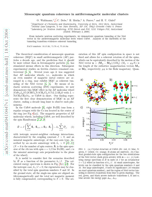
Microscopic Origin of Spatial Coherence and Wolf Shifts
- 格式:pdf
- 大小:103.42 KB
- 文档页数:7

2018年第37卷第12期 CHEMICAL INDUSTRY AND ENGINEERING PROGRESS·4821·化 工 进展α-酮异己酸的生物合成研究进展程申,张颂红,贠军贤(浙江工业大学化学工程学院,绿色化学合成技术国家重点实验室培育基地,浙江 杭州 310032) 摘要:α-酮异己酸是重要有机酸、药用氨基酸合成前体、新陈代谢调节因子和治疗药物,其生物合成路径条件温和,环境友好。
本文对α-酮异己酸的生理功能和体内代谢机理进行了归纳,并着重对其生物合成路径的研究进展进行了综述。
现有研究表明,α-酮异己酸可用葡萄糖为底物,通过代谢工程改造的谷氨酸棒杆菌或大肠杆菌工程菌发酵合成,但产物浓度较低;或以L-亮氨酸为底物,经氨基酸转氨酶、氧化酶、脱氨酶、重组工程菌或全细胞催化转化合成,产物浓度较高。
α-酮异己酸高产菌株的筛选、利用代谢工程方法对菌株进行改造以构建高效工程菌、发酵与分离提取工艺优化等问题,是今后需要研究的重点。
关键词:α-酮异己酸;生物合成;代谢工程中图分类号:Q939.97 文献标志码:A 文章编号:1000-6613(2018)12–4821–09 DOI :10.16085/j.issn.1000-6613. 2018-0193Recent advances in microbial synthesis of α-ketoisocaproateCHENG Shen, ZHANG Songhong,YUN Junxian(State Key Laboratory Breeding Base of Green Chemistry Synthesis Technology, College of Chemical Engineering,Zhejiang University of Technology, Hangzhou 310032, Zhejiang, China )Abstract :α-Ketoisocaproate (KIC) is not only an important organic acid and key precursor ofbranched chain amino acids for pharmaceuticals, but also a metabolic regulator and therapeutic agent. Biosynthesis pathway for the production of KIC has advantages of the mild reaction conditions and environment-friendly processes. In this work, the advances of the important physiological properties, the metabolisms and the biosynthetic pathways of KIC, were summarized. According to the references, two biosynthetic pathways are available for the preparation of KIC. The first one is the microbial fermentation approach using the strains of Corynebacterium glutamicum by metabolic engineering or recombinant Escherichia coli with glucose as the substrate, where the yield is low. The another is the enzymatic catalyzing using amino acid aminotransferases, oxidases or deaminases, the whole-cell bioconversion and the recombinant engineering strains using L-leucine as the substrate, where the yield is slightly high. Issues regarding the metabolic engineering improvement of the yield of KIC, the biosynthesis pathway, and the advanced fermentation and separation techniques, were proposed and considered as the important future research directions.Key words: α-ketoisocaproate ;biosynthesis ;metabolic engineeringα-酮异己酸(α-ketoisocaproate ,KIC )即4-甲基-2-氧代异己酸,是一种重要的高值有机酸和治疗药物,在生物体内可与L-亮氨酸相互转化,如图1所示。

土壤微塑料丰度的英文Soil Microplastic Abundance.Microplastics are small pieces of plastic that are less than 5 mm in size. They can come from a variety of sources, including the breakdown of larger plastic items, the use of microbeads in personal care products, and the release of plastic fibers from clothing. Microplastics can enter the soil through a variety of pathways, including atmospheric deposition, wastewater irrigation, and the application of biosolids.Once in the soil, microplastics can have a number of negative effects on soil health and ecosystem functioning. They can alter soil structure and water infiltration rates, reduce nutrient availability, and harm soil organisms. Microplastics can also sorb and transport pollutants, which can further contaminate the soil and groundwater.The abundance of microplastics in soil varies widelydepending on a number of factors, including the type of soil, the land use, and the proximity to sources of microplastic pollution. In general, microplastic abundanceis higher in urban and industrial areas than in rural areas. It is also higher in soils that are irrigated with wastewater or biosolids.A number of studies have investigated the abundance of microplastics in soil. One study, published in the journal Science of the Total Environment, found that the average microplastic abundance in agricultural soils was 4,000 particles per kilogram of soil. Another study, published in the journal Environmental Science & Technology, found that the microplastic abundance in urban soils was 10 times higher than in rural soils.The presence of microplastics in soil is a growing concern, and there is an urgent need for more research to understand the potential risks and develop mitigation strategies.Sources of Microplastics in Soil.Microplastics can enter the soil through a variety of pathways, including:Atmospheric deposition: Microplastics can be transported through the air and deposited on soil surfaces. This is a major source of microplastic pollution in remote areas.Wastewater irrigation: Wastewater contains a significant amount of microplastics, which can be released into the soil when wastewater is used for irrigation.Biosolids application: Biosolids are the solid waste produced by wastewater treatment plants. They contain a high concentration of microplastics, which can be released into the soil when biosolids are applied as a fertilizer.Landfill leachate: Landfill leachate is the liquidthat seeps out of landfills. It contains a high concentration of microplastics, which can be released into the soil when leachate escapes from landfills.Plastic mulches: Plastic mulches are used to coversoil and suppress weeds. They can release microplasticsinto the soil as they degrade.Effects of Microplastics on Soil Health.Microplastics can have a number of negative effects on soil health and ecosystem functioning, including:Altered soil structure: Microplastics can change the structure of soil, making it less porous and less able to hold water. This can lead to reduced plant growth and increased erosion.Reduced water infiltration rates: Microplastics can block soil pores, reducing the rate at which water can infiltrate the soil. This can lead to waterlogging and reduced plant growth.Reduced nutrient availability: Microplastics can sorb nutrients from the soil, making them unavailable to plants.This can lead to nutrient deficiencies and reduced plant growth.Harm to soil organisms: Microplastics can harm soil organisms, such as earthworms and nematodes. This candisrupt the soil food web and reduce the soil's ability to function properly.Microplastics and Pollutant Transport.Microplastics can sorb and transport pollutants, which can further contaminate the soil and groundwater. This is a particular concern for persistent organic pollutants (POPs), which are chemicals that do not break down easily in the environment. POPs can accumulate in microplastics and be transported to new areas, where they can pose a risk to human health and the environment.Conclusion.The presence of microplastics in soil is a growing concern, and there is an urgent need for more research tounderstand the potential risks and develop mitigation strategies. Microplastics can have a number of negative effects on soil health and ecosystem functioning, including altering soil structure, reducing water infiltration rates.。
Abstract— The identification of combinational protein interactions significantly challenges the field of systems biology and bio-computational informatics. The identification of protein-protein interactions along with their spatial and temporal localization is vital data for assigning functional information to proteins. Historically, these data sets obtained from fluorescence microscopy, have been analyzed manually, a process that is both time consuming and tedious. The development of an automated system that can measure the location dynamics of the interaction between two proteins inside a live cell is a high priority. This paper describes an automated image analysis system used to identify the interactions between two proteins of interest fused to either GFP or DIV IVA, a bacterial cell division protein that localizes to the cell poles [1]. Upon the induction of DIV IVA fusion protein expression, the GFP-fusion protein will be recruited to the cell poles if a positive interaction occurs. Advanced image processing and feature extraction algorithms are discussed in detail and a statistical feature set used to quantify the image based information is developed.Index Terms— Sub-cellular protein localization, protein-protein interaction, automated image analysis, feature extraction.I. INTRODUCTION AND BACKGROUND Functional and location proteomics with their high throughput information is revolutionizing current research in the post genomic era [2]. High throughput imaging studies produce large volumes of information rich data that can be both time-consuming and cumbersome to analyze manually. Until recently, significant effort had been channeled towards automating image analysis for applications involving computer vision for robots and medical imaging modalities like MRI, PET, and SPECT [3-4]. However, fewer examples exist in the field of optical microscopy of biological samples. Though image acquisition in this field has been automated for quite some time now, the analysis domain typically uses independent scorers to perform the task [7]. This is due to a variety of factors such as, the inability of generic image processing algorithms to exploit the highly information rich microscopic images, and more importantly the risk of improper interpretation of such images [5].With the advent of high throughput image collection and analysis tools, the field systems biology has the potential to explore new dimensions. Fluorescence microscopy, along with the advances made in the software industry has led to novel approaches to analyzing a wide range of problems in the field of proteomics [6]. Considering the large number of proteins, the study of protein localization is an application where automated image analytic solutions could enhance the speed and efficiency of the procedure.In this paper, we apply advanced image processing and pattern recognition techniques targeted at identifying positive protein-protein interactions using their location proteomics before and after the interaction. We choose a sample assay involving the interactions between two proteins of interest fused to either DIV IVA or GFP, where the DIV IVA localizes to the cells poles. Upon the induction of DIV IVA fusion protein expression, the GFP-fusion protein localizes at the cell poles if a positive interaction occurs; if not, we do not observe a change in the localization pattern of the protein of interest. From a set of Differential Interface Contrast (DIC) and fluorescent (Green Fluorescent protein) images, identification and quantification of individual cells and protein localization patterns can be carried out. An automated approach to do the same relieves tedious manual characterization. Assessment of multiple cells from a field of view is advantageous owing to the statistical information that can be obtained. However, this also creates significant challenges for automated analysis. For example, closely spaced cells can lead to erroneous cell counts. Moreover, cells on the verge of dividing have unusual shapes and an additional region of GFP localization at the medial division site. Another common problem with fluorescent microscopic images is the presence of background fluorescence. This is sometimes referred to as bleeding and can lead to ambiguous results. Finally, inclusion bodies (Intracellular protein aggregates that are usually observed in bacteria upon protein over expression.) when present need to be distinguished from authentic localization regions. This paper discusses various techniques employed to overcome such problems in order to achieve unambiguous results from automated image analyses.A set of sub-cellular location features for microscopic images aimed at automated classification of protein localization patterns has been developed in [7]. A few pertinent features from these studies along with a set of DIC images are used to identify positive interactions by quantifying a number of statistical features that include the number of cells in a given image, their individual Areas, Perimeters, Diameters, Roundness factor and center of gravity of the cells. Results from the algorithm were verified by an expert scorer. A visually information rich pseudo colored image defining the potential features of the image is created to facilitate image interpretation and performance assessment of the algorithm.Automated Image Analysis of Fluorescence Microscopic Images to Identify Protein-protein Interactions Sankar Venkataraman2, Jennifer L. Morrell-Falvey1, Mitchel J. Doktycz1, Hairong Qi21 Life Sciences Division, Oak Ridge National Laboratory, Oak Ridge, Tennessee 378312Electrical and Computer Engineering Department, University of Tennessee, Knoxville, TN 37996II. MATERIAL AND METHODSA. Sample Preparation and Image Acquisition Escherichia coli strain BL21-DE3 (Invitrogen, Carlsbad, CO) was co-transformed with two compatible vectors encoding pairs of potentially interacting proteins from R. palustris fused to either DivIVA or GFP. Construction of these vectors will be described in detail elsewhere (Morrell-Falvey and Doktycz, manuscript in preparation). The R. palustris gene products tested in this study include GroES1 (RPA1141), GroES2 (RPA2165), GroEL1 (RPA1140), and GroEL2 (RPA2164) [8]. For this assay, expression of the DivIVA fusion protein is tightly regulated by an arabinose inducible promoter [9] and the GFP fusion protein is expressed constitutively from a T7 promoter. Co-transformed cells were grown for at least 6 hours at 30˚C or 37˚C in LB medium containing 50g/ml ampicillin and 15g/ml chloramphenical to maintain plasmid selection and then imaged using a Leica SP2 confocal laser scanning microscope to determine the localization pattern of the GFP-fusion protein. Then, arabinose was added to the medium to a final concentration of 0.2% to induce expression of the DivIVA-fusion protein and the cells were incubated for an additional hour at 30˚C or 37˚C. Following induction of the DivIVA-fusion protein, the cells were imaged again to determine the new pattern of GFP-fusion protein localization. If the GFP-fusion protein is recruited to the cell poles following expression of the DivIVA-fusion protein, the data is interpreted as showing a positive interaction between the two proteins of interest fused to DivIVA and GFP. Images were processed using Leica Confocal Software (LCS).B. Image Processing Algorithm DevelopmentFigure 2 shows a block diagram that describes the flow of different steps implemented during our analyses. Owing to the visual similarity between images of inclusion bodies and those of a positive interaction, the same set of image processing and feature extracting steps are used to identify them before and after the induction of DIV IVA fusion protein expression. The presence of inclusion bodies in the sample is an experimental problem that can be inherent to the biological system under study. However, it acts as a hurdle to automating the process of image analysis as they look similar to GFP localization regions in the case of a positive interaction. An illustration of the problem caused by inclusion bodies is shown in Figure 1. A unique logical method of avoiding the problem of inclusion bodies due to protein over expression in bacterial cells is implemented here. It is achieved by acquiring a set of images (DIC and GFP) before initializing the reaction. The acquired DIC images were de-convolved using a Lucy-Richardson [10] de-convolution filter provided by MATLAB. After equalizing the histogram of the resultant deconvolved image, it goes through a Canny edge detector [11], morphological operators of opening and closing, and labeling function provided by MATLAB as bwlabel to identify the spatial region correlated to cells.Figure 1.Visual similarity between image of (left) a positive interaction and (right) inclusion bodies.The acquired GFP image goes through a different set of image processing steps as seen from Figure 2. A popular method to remove background fluorescence in fluorescent images is to subtract the most common pixel value from the image. Here, we employ a different algorithm to obtain a more efficient de-noising effect. The labeled DIC image obtained from the above processing steps is used to define a region corresponding to the cells. The grayscale values at spatial coordinates that do not belong to any of the individual cells, are made 0 (black) in the GFP image, in order to get rid of the background noise in the fluorescent image. Thus, the subsequent operations are limited to a specific region of interest. Figure 3 illustrates the effect of denoising.Figure 2. Methodology flow chartAn automated global threshold described in [12] was applied on the de-noised GFP image to obtain its corresponding binary image. This was then passed through a median filter in order to remove any other speckle noise that might be present and the resultant image was subsequently labeled. The percentage area occupied by the labeled spots within each cell is calculated, and uponexperimentation and observation, for images with inclusion bodies the value was found to be less than 60%. If inclusion bodies are present before induction of DIV IVA, the samplewas not analyzed further.Figure 3. GFP De-noising. Left: GFP image before De-noising; Right: GFP image after De-noisingOnce the absence of inclusion bodies in the sample is confirmed, a set of images (DIC and GFP) are acquired after inducing DIV IVA fusion protein expression. These images go through the same set of image processing operations as described above to result in noise-free labeled images. Binary images containing edge information of the cells, filled contour area of the cells and GFP spots are labeled independently. The three labeled images contain relevant data at specific spatial locations and the rest of them are featureless. Thus, they are then converted into a data matrix of three columns, containing spatial coordinates of the labeled pixels in the first two columns and the label itself in the third, thereby avoiding featureless portions of the image in subsequent iterations. The data matrix is used in order to enhance the speed of subsequent feature extraction procedures.C. Feature ExtractionA list of relevant features for microscopic images of cells is described in [6]. Not all the features are relevant to this study. Thus, a few pertinent ones were chosen:• Number of cells in an image which is calculated by counting the number of labels (or isolated segments) obtained from the DIC image.• Area occupied by individual cells that is obtained by counting the number of pixels under each filled contour label.• Perimeter of individual cells obtained by counting the number of pixels under each edge label.• Diameter of individual cells which is defined as the value of the greatest eccentricity that is, the longest distance between any two points on the perimeter of individual cells.• Roundness factor that quantifies the shape of an object calculated as ()π4/2−area perimeter• Center of gravity (COG) of cells and center of fluorescence (COF) of GFP localization regions. These features are obtained fromirci ii rci iA c r yI y A c r xI x /),(,/),(∑∑∑∑==where I i (r , c ) is the intensity of the i th labeled object at (r, c ) and A i is the area of that particular labeled object. • Distance of the GFP localization regions from the center of the corresponding cell that is the distance between COF and COG.• Percentage area occupied by protein localization regions within each cell calculated as the ratio of area occupied by GFP spots to that of the cell.• The number of localization regions within each cell that is extracted by treating each cell as an individual entity and labeling the GFP spots within it. Ideally, this number would be 2.• Percentage of cells with the desired localization patterns within an image.III. E XPERIMENTS , RESULTS AND ANALYSESThough the relative difficulty of acquiring a consistent set of DIC images is greater than that of acquiring a consistent set of images with membrane dyes, careful image acquisition procedures can solve the problem. A difference in gradients of intensity along the cell outline in DIC images was used as a criterion to define regions for further analyses of the fluorescent images. Another advantage of DIC images over membrane dyes was observed in the case of multiple cells sticking together. In a DIC image, we used the rapid increase of the difference in intensity gradient along the inner boundary of cells. Thus, as long as the inner boundary of any two cells does not overlap, they can successfully be identified as two separate cells, but a similar assessment could not be achieved in the case of an image with membrane dye. The edge properties in these images were found to be easily extractable by using simple edge detection techniques after some amount of preprocessing as explained in Sec. II.B. A Canny filter was chosen to extract the edges from the processed DIC image after evaluating other algorithms such as a Sobel filter and an active contour algorithm owing to its robustness to weak boundaries and easy implementation.In addition, the choice of an appropriate structuring element for morphological operations is critical. Since our object features (Cell contours) were smooth around the corners, a disk with a radius of 3 was employed. The three-dimensional data matrix mentioned Sec. II.B, saves computational time by ignoring the null values in each image and thus is a vital component of the algorithm.The number of GFP localization regions inside a given cell is first determined to assess if they are consistent with a positive interaction. For this particular assay, we know the desired characteristics of protein localization regions and thus check for their occurrence by looking for two such regions, one at each pole of the cell. The cell is divided into 3 regions along its diameter to identify the location (poles or the center) of GFP localization regions within it. The distance between centers of localization regions and the center of the cell gives an approximate indication of their location within the cell. Thus we count the number of cells that have 2 localization regions at the poles within it. This value is then used to calculate the success of interaction by obtaining the percentage of cells exhibiting the desired localization patterns. Figure 4 illustrates the image processing results generated from different steps mentioned above.Figure 4. DIC and GFP image processing results. From top to bottom, leftto right: given DIC image, given GFP image, binary DIC image beforelabeling, binary GFP image before labeling, and pseudo-colored finalimageThe Roundness factor described in Sec. II.C. acts as anidentification tool to spot splitting cells and other cellsdisplaying ambiguous results. Most of them display adifferent shape (dumbbell) than normal cells possessingdesired localization (ellipse) spots. In such a situation, a cellthat is in the stage of splitting can be identified with a highroundness factor. The roundness factor is calculated usingvalues obtained for area and perimeter of the cell as shownin equation 1.Thus, the various features extracted are put touse to enhance the quality of interpretation.The statistical features extracted using various algorithmsdiscussed in Sec. II was used to characterize a pair ofsample test images. These results are tabulated in Table 1.A final image that represents individual features in differentcolor channels is generated by pseudo coloring the targetlocations. An option of viewing the identity of a specificcell can be obtained by pointing on it in the image.CellNo.Area Per DiameterRoundnessfactor# ofGFPspotsCOG1 1491 148 67 135.4332 178 1142 1461 141 67 128.433 2 131 1623 1460 147 66 134.433 2 196 1544 1876 167 86 154.433 3 183 2255 1270 132 58 119.433 2 160 2586 1595 150 71 137.433 3 371 2787 1843 177 87 164.433 3 165 3118 1872 166 81 153.433 3 385 3089 1540 181 89 168.433 0 202 34410 1256 143 66 130.433 2 237 33611 922 113 56 100.433 2 173 34312 1414 142 68 129.433 2 208 39813 2163 192 92 179.433 3 432 427pixels. Percentage positive interactions in current image – 53.8).IV. C ONCLUSIONAn automated image analysis system for identifying thelocation of labeled protein in live cells was successfullydeveloped via algorithms implemented in MATLAB.Unique solutions to solve problems due to the ambiguityarising from cells undergoing cleavage, adjoining cells andthe problems caused by bleeding of GFP have been offered.Assigning functional information to the large number ofproteins is a major concern in the field of proteomics. Adirection towards that goal is to analyze protein-proteininteraction which involves huge data sets of fluorescentimages. Automated analyses of these humongous data setsof images can levitate the speed, accuracy and consistencyof such analyses. Results obtained from the algorithmdescribed in this paper will serve as the foundation for ourfurther research where we plan to analyze unknownlocalization patterns of many other protein-proteininteractions and set up a database for the same.The automation of real time microscopic imaging hasrevolutionized the field of genomics and proteomics. Anautomated real time image analyses system that works intandem with a real time image acquisition system couldreveal unexplored terrains in the post genomic era. Thealgorithm developed can be applied to various otherapplications involving fluorescent and DIC images withslight modifications. Such an algorithm can also beemployed to reduce the size of image datasets by selectingthose that possess desired features such as positiveinteractions or specific location patterns in it.Though the problem of closely spaced cells was solved toan extent, there are problems with huge clumps of cellswith many of them overlapping each other. Such problemshave to be better assessed and ideal segmentation solutionsare to be obtained as a part of our future work.R EFERENCES[1] Z. Ding, Z. Zhao, S.J. Jakubowski, et al. “A novel cytology-based,two-hybrid screen for bacteria applied to protein-protein interactionstudies of a type IV secretion system”, J. of Bacteriology, pp. 5572-5582, Oct. 2002.[2] M.V. Boland and R.F. Murphy, “After sequencing: Quantitativeanalysis of protein localization”, Engr. in Genomics, Oct. 1999.[3] D.W. Shattuck and R.M. Leahy, “Automated graph-based analysisand correction of cortical volume topology”, IEEE Trans. on MedicalImaging, vol. 20, no. 11, Nov. 2001.[4] B.W. Reutter, G.J. Klein, and R.H. Huesman, “Automated 3-Dsegmentation of respiratory-gated PET transmission images”, IEEETrans. on Nuclear Science, 44(6):2473–2476, 1997.[5] C.A. Glasbey, “Problems in digital microscopy”, Abstracts of InvitedPapers at XVIII Intern. Biometric Conf., Amsterdam, 183-200, 1996.[6] T.N. Davis, “Protein localization in proteomics”, Current Opinion inChemical Biology 8:49-53, 2004.[7] M.V. Boland and R.F. Murphy, “A neural network classifier capableof recognizing the patterns of all major sub-cellular structures influorescence microscope images of HeLa cells”, Bioinformaticsvol.17, no.12, 2001.[8] F.W. Larimer, P. Chain, L. Hauer, J. Lamerdin, S. Malfatti, et al.,“Complete genome sequence of the metabolically versatilephotosynthetic bacterium Rhodopseudomonas palustris”, Nat.Biotech, 22, 55, 2004.[9] L. Guzman, D. Belin, M.J. Carson, and J. Beckwith, “Tightregulation, modulation, and high level expression by vectorscontaining the arabinose PBAD promoter”, J. Bacteriol, 177, 4121,1995.[10] J. Astron, 79, 745 and 1972, J. Opt. Soc. Am. 62, 55, 1974.[11] J. Canny, “A computational approach to edge detection," IEEEPAMI, 8(6):678-698, 1986.[12] N. Otsu, ‘‘A threshold selection method from gray levelhistograms’’, IEEE Trans. Syst. Man Cybern. SMC-9, 62–66, 1979.。
应用固相微萃取技术分析番茄与天竺葵活体植株的挥发物*魏 明 邓晓军 胡文利 魏洪义 杜家纬**(中国科学院上海生命科学研究院植物生理生态研究所,上海200032)摘 要 应用固相微萃取技术(SPM E)和自行设计的挥发物收集装置对番茄和天竺葵的活体植株所释放的挥发性有机物(BV OCs)进行了色谱分析。
鉴定出番茄植株挥发物主要组成物质为A -蒎烯、A -萜品烯、水芹烯和桧烯等,天竺葵挥发物主要组成物质为A -蒎烯、莰烯、B -蒎烯、B -香叶烯、苎烯、石竹烯和A -草烯等。
而作为对照的常规通气吸附法则由于背景噪声复杂而未能有效鉴别出这两种植物活体植株的挥发物组成。
实验表明,本研究中建立的技术和装置能直接检测芳香植物活体所释放的挥发物的成分,并具有操作简便,无有机溶剂,重复性好等优点,适用于活体植物挥发性次生代谢物的相关研究。
关键词 固相微萃取,挥发物,收集装置,活体,色谱分析,通气吸附中图分类号 Q 949 文献标识码 A 文章编号 1000-4890(2004)04-0184-04Analysis of volatile chemicals em itted from living tomato and geranium samples with SPME tech -nique.W EI M ing ,DENG Xiaojun,HU Wenli,W EI Hong yi,DU Jiaw ei (Shanghai I ns titute of Plant Physiology and Ecology ,S hanghai I nstitutes f or Biological Sciences ,Chinese A cademy of Sciences ,Shanghai 200032,China).Chinese Journal of Ecology ,2004,23(4):184~187.So lid phase micro ex tract ion(SPM E)technique was applied to collect the biog enic volatile or ganic compounds(BV OCs)emitted from liv ing samples of tomato and geranium.A set of collecting devices desig ned by the authors was used in these experiments too.A nd t hen,the BV OCs collected were sent to be analyzed by the chromatogr am analysis system.T he major components in the BVOCs from tomato samples were identified as A -pinene,A -ter pinene,phellandrene,sabinene and some unknow n chemicals.And A -pinene,camphene,B -pinene,B -myrcene,limonene,caryophyllene and A -humulene were found in t he BVO Cs from geranium samples.In contrast,the control ex periments which em -ployed t he co nventional aerating abso rption system could not tell the certain volatile chemicals of tomato and g eranium because of the complex background.T hese exper iments indicated that t he tech -nique and dev ices established in this research were effective to ident ify the BVO Cs emitted fr om the liv ing aromatic plants directly,w ith the advant ag es such as clean -backg round,convenience,g ood re -peatability and solv ent -free.So this system can be a valuable method to study the volatile second metabolic chemicals in living plants.Key words Solid phase microex traction,V olatile compounds,Collecting devices,L iving samples,Chromatogram analysis,Aerated adsorption.*中国科学院知识创新工程项目(KSCX2-2-02)和2002年上海市科学技术委员会资助项目(023912004)。
第 35 卷 第 1 期环 境 科 学 研 究Vol.35,No.1 2022 年 1 月Research of Environmental Sciences Jan.,2022电活化过硫酸盐去除铜绿微囊藻的效果及机理研究郑婷婷1,2,3,牟 霄4,张崇淼1,2,3*,曹梦璇1,2,31. 西安建筑科技大学环境与市政工程学院, 陕西西安 7100552. 西安建筑科技大学, 陕西省环境工程重点实验室, 陕西西安 7100553. 西安建筑科技大学, 西北水资源与环境生态教育部重点实验室, 陕西西安 7100554. 陕西省食品药品检验研究院, 陕西西安 710065摘要:为了开发微藻及藻类有机物的高效去除技术,采用电活化过硫酸盐(EC/PS)体系处理含铜绿微囊藻的水样. 通过藻细胞密度和叶绿素a含量测定以及扫描电镜观察,研究了EC/PS体系的除藻特性及影响因素;采用荧光区域积分法定量分析了除藻过程中胞内有机物(IOM)和胞外有机物(EOM)的变化特征;利用电子顺磁共振波谱仪测定了EC/PS体系中的自由基类别,并分析了EC/PS体系的除藻机理. 结果表明:①在初始藻细胞密度为1.24×10⁷~1.30×10⁷ cells/mL,电压为7 V,初始pH为6,初始PS浓度为4 mmol/L的条件下,当EC/PS体系处理60 min时,藻细胞和叶绿素a的去除率分别达90.80%和98.41%,明显优于单独EC 体系和单独PS体系;当EC/PS体系处理10 min时,IOM的总荧光响应值降低了77.39%. 在处理过程中,以腐殖酸类物质为主的胞内有机物会大量释放. ②EC/PS体系中电化学作用对除藻的平均贡献率为54.63%;同时,除藻过程可产生大量的SO4−·和·OH,且其随处理时间的增加而增加. 研究显示,EC/PS体系能有效去除铜绿微囊藻及藻类有机物,反应体系中的SO4−·和·OH发挥了重要作用.关键词:电活化过硫酸盐(EC/PS);铜绿微囊藻;胞内有机物;胞外有机物;自由基中图分类号:X524文章编号:1001-6929(2022)01-0098-10文献标志码:A DOI:10.13198/j.issn.1001-6929.2021.07.05Removal Performance and Mechanisms of Microcystis aeruginosa by Electro-Activated PersulfateZHENG Tingting1,2,3,MOU Xiao4,ZHANG Chongmiao1,2,3*,CAO Mengxuan1,2,31. School of Environmental and Municipal Engineering, Xi'an University of Architecture and Technology, Xi'an 710055, China2. Shaanxi Key Laboratory of Environmental Engineering, Xi'an University of Architecture and Technology, Xi'an 710055, China3. Key Laboratory of Northwest Water Resource, Environment and Ecology, Ministry of Education, Xi'an University of Architecture and Technology, Xi'an 710055, China4. Shaanxi Institute for Food and Drug Control, Xi'an 710065, ChinaAbstract:In order to develop a technology for efficient removal of microalgae and algal organic matter, an electro-activated persulfate (EC/PS) system was used to treat water samples containing Microcystis aeruginosa. The characteristics and influencing factors of the EC/PS system for Microcystis aeruginosa removal were studied through determination of cell density and chlorophyll-a and scanning electron microscopy. Fluorescence regional integration method was used to quantitatively analyze the fluorescence intensity of each region, and the changes of intracellular organic matter (IOM) and extracellular organic matter (EOM) associated with Microcystis aeruginosa during the EC/PS treatment were studied. The free radicals in EC/PS system were determined by electron paramagnetic resonance and the mechanism of algae removal was analyzed. The results showed that: (1) After 60 min of EC/PS treatment, the removal rates of algal cells and chlorophyll-a reached 90.80% and 98.41%, respectively, under the conditions of initial algal density of 1.24×10⁷-收稿日期:2021-05-06 修订日期:2021-07-14作者简介:郑婷婷(1995-),女,河南开封人,2472847303@.*责任作者,张崇淼(1978-),男,河南郑州人,教授,博士,博导,主要从事水环境微生物风险评价与控制、污水处理与资源化研究,cmzhang@基金项目:陕西省重点研发计划项目(No.2020ZDLNY06-07)Supported by Key Research and Development Program of Shaanxi, China (No.2020ZDLNY06-07)1.30×10⁷ cells/mL, the voltage of 7 V, the initial pH of 6, and the PS concentration of 4 mmol/L. It was better than a separate EC systemand a separate PS system; The total fluorescence response value of IOM decreased by 77.39% after 10 min of EC/PS treatment, and a large number of intracellular organic matters dominated by humic acids were released during treatment processing. (2) In EC/PS system, the average contribution rate of electrochemical action to algae removal was 54.63%; At the same time, a large amount of SO4−· and ·OH were produced during the algae removal process, which increased with the increase of treatment time. This study showed that algae and theirorganic matters could be effectively removed by EC/PS system, in which SO4−· and ·OH played an important role.Keywords:electro-activated persulfate (EC/PS);Microcystis aeruginosa;intracellular organic matter;extracellular organic matter;free radical近年来,由于全球气候变暖和水体营养负荷的增加,导致世界范围内频繁出现水体富营养化现象,进而诱发不同程度的藻类暴发[1-2].铜绿微囊藻(Microcystis aeruginosa)是蓝藻水华中最常见的优势藻种,在其生长繁殖过程中会产生大量的藻类有机物,包括胞内有机物(intracellular organic matter, IOM)和胞外有机物(extracellular organic matter, EOM)[3]. 藻细胞及其藻类有机物对人体健康有较大威胁[4],但传统的水处理工艺对藻细胞及其藻类有机物的去除效果并不理想[5].基于过硫酸盐(persulfate, PS)的高级氧化技术在难降解有机污染物的去除方面已经得到广泛的应用[6]. PS本身性质稳定,但通过热[7]、紫外线[8]、碱[9]、超声[10]、电化学(electrochemical, EC)[11]、金属及金属氧化物[12]等方式活化后,能在水溶液中产生具有强氧化能力的硫酸根自由基(SO4−·)和羟基自由基(·OH),从而高效去除污染物. 目前,常用的PS活化方式是紫外线辐照,然而,紫外线的辐照强度会受到水中颗粒物的阻挡[13]、腐殖酸等[14]物质的吸收而大幅衰减,故在PS活化的应用中存在明显的缺陷. EC作为一种高效、清洁的高级氧化技术,在活化PS方面有显著优势[15]. 有研究表明,EC/PS体系对60 mg/L TOC的去除率较单独EC体系高34%[16]. 此外,EC 和PS氧化在去除2-甲氧基苯酚[17]、阿特拉津[18]、二硝基甲苯[19]等污染物上还具有协同效应. 目前,有关EC/PS体系氧化除藻的研究还很不充分,以往研究证实了紫外活化PS去除铜绿微囊藻的可行性[20],但对除藻过程中藻类有机物的变化缺乏深入分析[21].鉴于此,该研究采用EC/PS体系去除水中的铜绿微囊藻,探究EC/PS体系除藻的效能及影响因素.在三维荧光光谱(three-dimensional excitation emission matrix fluorescence spectroscopy, EEM)测定的基础上,使用荧光区域积分(fluorescence regional integration, FRI)法对EC/PS体系除藻过程中IOM和EOM进行定量分析,并借助电子顺磁共振波谱仪(electron paramagnetic resonance, EPR)对EC/PS体系除藻机制进行探索,以期为EC/PS体系应用于去除微藻和藻类有机物提供科学依据.1 材料与方法1.1试验材料试验藻种为铜绿微囊藻(Microcystis aeruginosa, FACHB-905),购自中国科学院水生生物研究所. 使用BG11培养基培养,放置在(25±1)℃光照培养箱中,设置光暗比为14 h∶10 h,光照强度为1 000~2 000 lx,每天早中晚各摇匀一次. 过硫酸钠(Na2S2O8)、磷酸氢二钠(Na2HPO4)、磷酸二氢钠(NaH2PO4·2H2O)、无水硫酸钠(Na2SO4)、氢氧化钠(NaOH)、硫酸(H2SO4)、无水乙醇(C2H6O)和50%戊二醛水溶液(C5H8O2)均购自天津科密欧化学试剂有限公司;BG11培养基购自青岛海博生物技术有限公司;5,5-二甲基-1-吡啶-N-氧(DMPO)购自阿拉丁试剂有限公司. 试验使用的化学试剂均为分析纯,试验用水均为Milli-Q超纯水.1.2试验装置该研究采用EC/PS体系反应装置,电解槽容积为240 mL,长×宽×高为60 mm×50 mm×80 mm. 阳极材料为镀有氧化铱和氧化钌的钛板(Ti/IrO2-RuO2),该电极材料具有相对稳定、电催化活性高及价廉的优点,阴极材料为钛板(Ti),两电极板的尺寸均为50 mm×90 mm×1 mm.固定两极板之间的距离为40 mm,此时两极板间的有效电解体积相对较大,两极板之间连接一个直流稳压电源[22].1.3藻细胞密度和叶绿素a含量的测定使用紫外-可见分光光度计(UV1800PC型,上海菁华科技仪器有限公司)测定铜绿微囊藻在680 nm 处的光密度值(OD),用以反映铜绿微囊藻的细胞密度[23]. 其中,藻细胞光密度值OD680与浮游植物计数法得到的藻细胞密度之间有良好的线性关系,即藻细胞密度(106 cells/mL)=63.896×OD680−0.395 1,R2= 0.992 1.采用热乙醇法[24]测定样品中的叶绿素a含量. 取第 1 期郑婷婷等:电活化过硫酸盐去除铜绿微囊藻的效果及机理研究99一定体积的藻液抽滤过0.45 μm 滤膜,将截留藻细胞的滤膜破碎成若干条状放入试管中,于−20 ℃冰箱避光冷冻24 h 后,加入10 mL 90%的热乙醇(80 ℃),于80 ℃的水浴锅中水浴2 min ,于超声波清洗机中超声10 min ,室温下避光萃取5 h ,之后用一次性注射器吸取6 mL 萃取液过25 mm 滤头,滤液用于比色测样[25]. 叶绿素a 含量的计算公式:式中:C 为叶绿素a 含量,mg/m 3;V a 为乙醇提取液体积,mL ;V b 为样品体积,L ;E 665、E 750分别为提取液在665 nm 和750 nm 处的吸光度值;A 665、A 750分别为经1 mol/L 稀盐酸酸化后的提取液在665 nm 和750 nm 处的吸光度值.1.4 EC/PS 体系除藻试验使用对数生长期的试验藻液(藻细胞浓度约为1.24×10⁷~1.30×10⁷cells/mL)进行EC/PS 体系除藻试验:取180 mL 藻液,用0.1 mmol/L 的H 2SO 4和NaOH 调节其初始pH ,加入一定量的Na 2SO 4,使其最终浓度为2 mmol/L ,以Na 2S 2O 8作为PS 的来源. 将混合液置于电解槽内,调节直流稳压电源的输出电压,开始除藻试验. 处理时长为60 min ,每隔10 min 取样测定藻细胞密度和叶绿素a 含量. 铜绿微囊藻及其叶绿素a 的去除率分别如式(2)(3)所示:式中:η和η′分别为铜绿微囊藻及其叶绿素a 的去除率,%;OD 0和OD t 分别为除藻试验开始前和t 时刻的光密度值;C 0和C t 分别为除藻试验开始前和t 时刻的叶绿素a 含量,mg/m 3.单独PS 体系除藻试验和单独EC 体系除藻试验分别是在不通电和不加入PS ,但其余条件不变的情况下进行的. 所有试验均重复两次,并计算相应平均值±标准差.1.5 藻细胞微观形态观察取40 mL 含藻水样于5 000 r/min 离心5 min ,弃上清液,再用20 mL 含4%戊二醛的磷酸盐缓冲液重悬藻浆并静置4 h ,离心弃上清液. 用上述缓冲液反复清洗离心3次,经梯度乙醇脱水、冷干、喷金后,用扫描电子显微镜(SEM)(JSM-6510LV 型,日本电子株式会社)在电压为15 kV 下观察藻细胞形态[26].1.6 IOM 和EOM 的三维荧光光谱分析含藻水样于6 000 r/min 离心10 min 后分离上清液和沉淀,上清液经0.45 μm 混合纤维滤膜过滤,滤液用于测定EOM ;向装有沉淀的离心管内加入等体积的超纯水,混合均匀,按上述离心条件清洗1次,弃上清液,将沉淀反复冻融3次,重溶于等体积的超纯水中,镜检以确保80%以上的藻细胞被破坏,最后过0.45 μm 混合纤维滤膜过滤,滤液用于测定IOM [27].利用荧光光谱仪(F-7000型,日本HATACHI 公司)测定EOM 和IOM 的三维荧光光谱,该仪器具有高灵敏度,水拉曼光信噪比>800. 设置发射波长(λEm )以5 nm 间隔从250 nm 增至550 nm ,激发波长(λEx )则以1 nm 的间隔从200 nm 增至450 nm ,扫描速度为2 400 nm/min ,试验结果需要减去超纯水的三维荧光光谱以消除超纯水的拉曼散射峰[28-29]. 使用Origin软件绘制三维荧光光谱,并依据Chen 等[30]的方法划分荧光区域,根据λEm 和λEx 的范围可将三维荧光光谱谱图划分为5个区域,分别对应不同类型的物质:区域Ⅰ和Ⅱ代表芳香蛋白类物质;区域Ⅲ代表富里酸类物质;区域Ⅳ代表溶解性微生物代谢产物;区域Ⅴ代表腐殖酸类物质. 按照FRI 法对各区域的荧光强度进行定量分析,考虑到实际数据的荧光强度是离散数据点,所以采用离散型积分〔见式(4)〕进行FRI计算:式中:Φi 为第i 区域的荧光体积积分,a.u.·nm 2;∆λEx 为激发波长间隔,取值为1 nm ;∆λEm 为发射波长间隔,取值为5 nm ;I (λEx, λEm )为每个激发-发射波长对应的荧光强度,a.u..1.7 TOC 含量测定分别取40 mL 经EC/PS 体系处理10、30和60 min 后的含藻水样以及未经处理的含藻水样,经过0.45 μm 混合纤维滤膜过滤后,收集滤液,使用有机碳(TOC)分析仪(Vario TOC CUBE 型,德国元素)测定水中TOC 含量.1.8 自由基检测使用电子顺磁共振波谱仪(EPR)(ZMXmicro-6/1型,德国布鲁克公司)对样品中的自由基进行测定.样品与5,5-二甲基-1-吡咯啉-N-氧化物(DMPO)溶液快速混匀,用毛细管吸取一定量的混合液,于EPR 的共振腔中进行测定. EPR 的主要参数设置:中心磁场磁感应强度为3 500 G ;扫场宽度为200 G ;扫场时间为87.64 s ;g 因子为2.000 00;微波频率为31.70 mW.1.9 EC/PS 体系中主要因素的除藻贡献率为了解EC/PS 体系中EC 作用的贡献情况,根据式(5)计算其相应的贡献率(R 1),根据式(6)计算EC/PS 体系中除EC 作用外的其他因素对除藻的贡100环 境 科 学 研 究第 35 卷献率(R 2).式中:A t 为单独EC 体系的除藻率,%;A 0为EC/PS 体系的除藻率,%.2 结果与讨论2.1 单独EC 、单独PS 和EC/PS 体系除藻效果比较由图1可见,在电压为7 V 、初始pH 为6、处理时间为60 min 时,单独EC 体系处理铜绿微囊藻的藻细胞和叶绿素a 去除率分别为55.52%、65.66%,具有一定的除藻效果. 这主要依靠电极的直接氧化及电极表面产生的·OH 发挥作用[31]. 当电压为7 V 、初始pH 为6时,单独使用4 mmol/L 的PS 处理60 min 后,藻细胞去除率仅为1.94%,叶绿素a 的去除率为11.47%,表明未经活化的PS 几乎没有除藻效果. 相比之下,EC/PS 体系的除藻效果远优于单独EC 体系和单独PS 体系. 在电压为7 V 、初始pH 为6、初始PS 浓度为4 mmol/L 的条件下处理60 min 后,藻细胞和叶绿素a 的去除率分别高达90.80%和98.41%,这表明EC/PS 体系不仅能破坏铜绿微囊藻的藻细胞结构,还能损伤其光合作用功能.可能的原因是EC 成功激活了PS 的氧化性能,产生具有较强氧化性能的活性物质SO 4−·,自由基的存在进一步促进了藻细胞的去除[32].图 1 不同处理体系对铜绿微囊藻藻细胞和叶绿素a 的去除率Fig.1 Removal rates of Microcystis aeruginosa cells and chlorophyll-a by different treatment systems2.2 EC/PS 体系除藻的影响因素研究电是活化PS 的能量来源. 电压直接决定体系中活性物质的产生速率,是EC/PS 体系关键的影响因素[33]. 由图2(a)可知,随着电压的增加,藻细胞去除率也在逐渐提高,电压从3 V 增至9 V 时,处理60 min 后,藻细胞的去除率从30.71%增至79.35%. 增加电压固然能提高除藻率,但在7 V 以上的提升幅度并不明显,过高的电压还会导致水的电解和析氧反应的加剧[34],增加体系能量损失,因此,在EC/PS 体系中选择电压为7 V 比较合适.pH 可通过影响活性物质的产生或转化来影响除藻效果[35]. 为了模拟自然水环境,该研究考察了EC/PS 体系初始pH 为6~9条件下的除藻效果. 由图2(b)可以看出,pH 的改变对EC/PS 体系的除藻效果影响不大,随着pH 升高,藻细胞的去除率从68.80%逐渐降至63%,可能是由于酸性条件更有利于SO 4−·的稳定存在造成的[15],因此以pH 为6开展后续研究.PS 浓度决定了EC/PS 体系中主要活性物质的生成量进而影响除藻效果. 如图2(c)所示,当初始PS 浓度从1 mmol/L 增至4 mmol/L 时,处理60 min 后的藻细胞去除率由68.80%增至90.80%,藻细胞去除率随初始PS 浓度的增加而升高,但是当初始PS 浓度增至8 mmol/L 时,藻细胞的去除率(85.07%)反而下降. 当初始PS 浓度过大时,EC/PS 体系中的S 2O 8−会与SO 4−·发生自淬灭反应[36],从而降低藻细胞的去除率. 因此,初始PS 浓度为4 mmol/L 时最有利于EC/PS 体系除藻.2.3 EC/PS 体系处理对藻细胞结构的影响EC/PS 体系除藻过程中铜绿微囊藻细胞的形态变化如图3所示. 由图3可见:EC/PS 体系处理前藻第 1 期郑婷婷等:电活化过硫酸盐去除铜绿微囊藻的效果及机理研究101图 2 EC/PS 体系中电压、pH 和初始PS 浓度对除藻效果的影响Fig.2 Effect of voltage, pH and initial PS concentration on algae removal in EC/PS system图 3 EC/PS 体系处理过程中藻细胞的SEM 图Fig.3 SEM images of algae cells in duration of EC/PS system102环 境 科 学 研 究第 35 卷细胞饱满且表面光滑;处理10 min后,部分藻细胞表面出现皱缩和破裂;处理30 min后,大部分藻细胞褶皱严重,可见有胞内物质向外释放;处理60 min后,视野内几乎不存在完整的藻细胞. 这表明EC/PS体系处理能显著损伤藻细胞结构,随着处理时间的延长,损伤加剧,藻细胞内物质会逐渐释放到胞外.2.4 EC/PS体系除藻过程中藻类有机物的荧光分析EC/PS体系处理前、处理10、30和60 min时IOM和EOM的三维荧光光谱变化如图4、5所示. 由图4、5可见:EC/PS体系处理前,IOM含有多种不同类型的物质,其中溶解性微生物代谢产物最多;开始EC/PS体系处理后,IOM中的各类物质都迅速减少. EOM的情况则大相径庭,EC/PS体系处理前主要为溶解性微生物代谢产物,还有少量的腐殖酸类物质.随着EC/PS体系处理的进行,溶解性微生物代谢产物逐渐减少,但腐殖酸类物质却有明显的增加. 特别是当EC/PS体系处理30 min时,腐殖酸类物质荧光峰值达到最大,区域V的荧光信号增加和区域IV的荧光信号减少几乎是同步的.利用FRI法对IOM和EOM的三维荧光光谱中5个区域的荧光强度进行积分计算. 由图6可以看出,IOM的总荧光响应值随EC/PS体系处理时间的延长而降低,且降幅逐渐减小. 处理10 min时IOM的总荧光响应值降低了77.39%,处理60 min时IOM的总荧光响应值较初始状态降低了93.16%,说明EC/PS 体系能在短时间内大幅降低IOM含量. 相比之下,EOM的总荧光响应值并未随着EC/PS体系处理而明显降低,处理60 min时EOM的总荧光响应值较初始状态下降了20.40%,但在处理30 min时EOM的总荧光响应值比初始状态还高6.79%,这应该与此时藻细胞大量破碎,以腐殖酸类物质为主的胞内物质集中释放有关. 在EC/PS体系处理过程中,EOM的变化情况比较复杂,一方面受到氧化作用而不断降解;另一方面则由于细胞破裂导致IOM释放增加,当IOM的注: Ⅰ和Ⅱ为芳香蛋白类物质; Ⅲ、Ⅳ、Ⅴ分别为富里酸类物质、溶解性微生物代谢产物、腐殖酸类物质. 下同.图 4 EC/PS体系处理过程中IOM的三维荧光光谱Fig.4 EEM spectra of IOM in duration of EC/PS system第 1 期郑婷婷等:电活化过硫酸盐去除铜绿微囊藻的效果及机理研究103释放占主导作用时,EOM 含量就会相对增加.此外,经EC/PS 体系处理10、30和60 min 后,含藻水样TOC 含量分别为9.19、8.89和4.54 mg/L ,而EC/PS 体系处理前TOC 含量为5.91 mg/L. 这表明含藻水样经EC/PS 体系短暂处理后即可释放大量有机物,随着处理时间延长这些有机物逐渐被矿化. 比较EC/PS 体系处理过程中TOC 含量和EOM 的荧光响应值,发现二者并不存在相关关系(P >0.05). 值得注意的是,EOM 荧光响应值的峰值出现时间要晚于TOC 含量的峰值出现时间. 推测是藻细胞结构和化学组成导致的,铜绿微囊藻细胞含有大量的多糖类物质,藻细胞壁中有胶鞘多糖,藻细胞表面则是由胞外图 5 EC/PS 体系处理过程中EOM 的三维荧光光谱Fig.5 EEM spectra of extracellular organic matter in duration of EC/PS system图 6 EC/PS 体系处理过程中IOM 和EOM 的荧光响应值Fig.6 Fluorescence responses of IOM and EOM in the process of EC/PS system104环 境 科 学 研 究第 35 卷多糖形成的黏滞性荚膜和黏液层[37]. 开始进行EC/PS 体系处理后,这些多糖成分首先遭到破坏,从而使水中TOC含量突增. 然而,需要处理一段时间后才会使藻细胞结构崩坏,细胞内物质大量释放,而这些物质种类复杂,其中芳香结构蛋白、腐殖酸类等物质都具有荧光性[38].2.5 EC/PS除藻体系的机理分析为了解EC/PS体系的除藻机理,对图1所示的结果做进一步分析,得到EC/PS体系中各因素的除藻贡献率(见图7). 在整个除藻过程中EC的平均贡献率为54.63%,在EC/PS体系中,EC的除藻主要由电极的直接电解和电解水产生的·OH〔见式(7)〕共同作用完成[31]. EC/PS体系中除EC作用外的其他因素主要依靠PS活化后产生的强氧化性自由基发挥作用.随着处理时间的增加,其贡献率出现先增后降的趋势,这主要是因为反应初期,EC/PS体系中的强氧化性自由基主要用于破坏藻细胞结构,随着处理时间的延长,胞内物质大量向外释放,部分强氧化性自由基则用于去除藻类有机物.图 7 EC/PS体系中各因素的除藻贡献率Fig.7 The contribution rate of each factor toalgae removal in EC/PS system通过EPR测定可检测出EC/PS体系中主要自由基类别,DMPO与SO4−·和·OH可分别生成自旋加合物DMPO-SO4−·和DMPO-·OH,从而被EPR检测到,对应产生强度比为1:1:1:1:1:1的组峰和1:2:2:1的组峰[39]. 由图8可知:在单独PS体系内,存在DMPO-SO4−·和DMPO-·OH组峰,这是因为PS水解会产生少量的SO4−·〔见式(8)〕;同时,SO4−·能进一步与水反应生成·OH〔见式(9)〕[32]. 随着EC/PS体系处理时间的增加,体系中的SO4−·和·OH信号逐渐增强. 这表明电化学体系在不断地活化PS,使其产生SO4−·〔见式(10)(11)〕,体系内的·OH由电解水产生的·OH〔见式(7)〕以及SO4−·与水反应后产生的·OH〔见式(9)〕共同构成. EC/PS体系中的SO4−·和·OH与除藻效果和藻类有机物的变化密切关联,这两种自由基是发挥除藻作用的主要活性物质.图 8 EC/PS体系处理过程中的自由基特征峰Fig.8 Characteristic peaks of free radicals induration of EC/PS system3 结论a) EC/PS体系处理可有效地去除水中的铜绿微囊藻藻细胞和叶绿素a,在初始藻密度为1.24×107~ 1.30×10⁷ cells/mL,电压为7 V、初始pH为6、初始PS浓度为4 mmol/L的条件下,处理60 min时藻细胞和叶绿素a的去除率分别可达90.80%和98.41%.b) EC/PS体系处理能在短时间内大幅降低IOM 的总荧光相应值,处理10 min时,IOM的总荧光响应值降低了77.39%. 除藻过程中藻细胞不断破裂,以腐殖酸类物质为主的胞内物质的释放导致EOM下降缓慢,处理60 min时EOM的总荧光响应值较初始状态仅下降了20.40%. 此外,EOM的荧光响应值峰值出现时间要晚于TOC含量峰值的出现时间.c) EC/PS体系中电化学作用对除藻的平均贡献率为54.63%;同时,EC/PS体系中存在SO4−·和·OH,且其随处理时间的延长逐渐增加,在藻细胞和藻类有机物的去除上发挥重要作用.参考文献(References):SMITH V H.Eutrophication of freshwater and coastal marineecosystems a global problem[J].Environmental Science and [1]第 1 期郑婷婷等:电活化过硫酸盐去除铜绿微囊藻的效果及机理研究105Pollution Research ,2003,10(2):126-139.朱喜, 朱云.太湖蓝藻暴发治理存在的问题与治理思路[J ].环境工程技术学报,2019,9(6):714-719.ZHU X, ZHU Y.Problems and countermeasures of controlling cyanobacteria bloom in Taihu Lake [J ].Journal of Environmental Engineering Technology ,2019,9(6):714-719.[ 2 ]LI L ,GAO N Y ,DENG Y ,et al. Characterization of intracellular & extracellular algae organic matters (AOM) of Microcystic aeruginosa and formation of AOM-associated disinfection byproducts and odor & taste compounds [J ]. Water Research ,2012,46(4):1233-1240.[ 3 ]王靖国, 邹华, 张强, 等.太湖微囊藻毒素的时空分布特征[J ].环境科学研究,2014,27(7):696-703.WHANG J G, ZOU H, ZHANG Q, et al.Spatial and temporal distribution of microcystin in Taihu Lake [J ].Research of Environmental Sciences ,2014,27(7):696-703.[ 4 ]LUI Y S, QIU J W, ZHANG Y L, et al.Algal-derived organic matter as precursors of disinfection by-products and mutagens upon chlorination [J ].Water Research ,2011,45(3):1454-1462.[ 5 ]冯俊生, 姚海祥, 蔡晨, 等.微生物燃料电池电活化过硫酸盐降解甲基橙偶氮染料[J ].环境科学研究,2019,32(5):913-920.FENG J S, YAO H X, CAI C, et al.Microbial fuel cell electro-activated persulfate to degrade methyl orange azo dye [J ].Research of Environmental Sciences ,2019,32(5):913-920.[ 6 ]CHEN Y Q, DENG P Y, XIE P C, et al.Heat-activated persulfateoxidation of methyl- and ethyl-parabens: effect, kinetics, and mechanism [J ].Chemosphere ,2017,168:1628-1636.[ 7 ]沈一君, 彭明国, 徐彬焜, 等.紫外活化过硫酸盐降解二苯甲酮-4的动力学影响及降解机理与风险评价[J ].环境科学研究,2019,32(1):174-182.SHEN Y J, PENG M G, XU B K, et al.Degradation of BP4 by UV-activated persulfate process: kinetic, mechanism and risk [J ].Research of Environmental Sciences ,2019,32(1):174-182.[ 8 ]QI C D, LIU X T, MA J, et al.Activation of peroxymonosulfate by base: implications for the degradation of organic pollutants [J ].Chemosphere ,2016,151:280-288.[ 9 ]WANG X E, WANG L G, LI J B, et al.Degradation of acid orange7 by persulfate activated with zero valent iron in the presence of ultrasonic irradiation [J ].Separation and Purification Technology ,2014,122:41-46.[10]CHEN L C, LEI C J, LI Z J, et al.Electrochemical activation ofsulfate by BDD anode in basic medium for efficient removal of organic pollutants [J ].Chemosphere ,2018,210:516-523.[11]GUO W L ,SU S N ,YI C L ,et al. Degradation of antibioticsamoxicillin by Co 3O 4-catalyzed peroxymonosulfate system [J ].Environmental Progress & Sustainable Energy ,2013,32(2):193-197.[12]濮晨熹, 郭大滨, 胡沔, 等.颗粒物的庇护作用对紫外线消毒效果的影响[J ].中国给水排水,2017,33(13):73-76.PU C X, GUO D B, HU M A, et al.Effect of particle protection in ultraviolet disinfection [J ].China Water & Wastewater ,2017,33[13](13):73-76.王秀娟, 胡学香, 胡春.水质对紫外消毒在两种典型再生水中应用的影响[J ].环境工程学报,2012,6(12):4289-4293.WANG X J, HU X X, HU C.Influence of water quality on UV disinfection in two typical reclaimed waters [J ].Chinese Journal of Environmental Engineering ,2012,6(12):4289-4293.[14]郭丽, 袁颐进, 冯丽贞, 等.电活化过硫酸盐降解全氟辛酸及其中间产物的探究分析[J ].环境科学学报,2020,40(6):2045-2054.GUO L, YUAN Y J, FENG L Z, et al.Electrochemical activated persulfate to degrade perfluorooctanoic acid and the analysis of intermediate products [J ].Acta Scientiae Circumstantiae ,2020,40(6):2045-2054.[15]CHEN W S ,HUANG C P. Mineralization of aniline in aqueoussolution by electrochemical activation of persulfate [J ].Chemosphere ,2015,125:175-181.[16]陈希, 纪志永, 黄智辉, 等.电化学协同过硫酸盐氧化法处理含盐有机废水[J ].化工进展,2019,38(12):5572-5577.CHEN X, JI Z Y, HUANG Z H, et al.Electrochemical synergistic persulfate oxidation process for treatment of salty organic wastewater [J ].Chemical Industry and Engineering Progress ,2019,38(12):5572-5577.[17]BU L J, ZHU S M, ZHOU S Q.Degradation of atrazine byelectrochemically activated persulfate using BDD anode: role of radicals and influencing factors [J ].Chemosphere ,2018,195:236-244.[18]CHEN W S ,JHOU Y C ,HUANG P H. Mineralization ofdinitrotoluenes in industrial wastewater by electro-activated persulfate oxidation [J ]. Chemical Engineering Journal ,2014,252:166-172.[19]WANG Z P, CHEN Y Q, XIE P C, et al.Removal of Microcystisaeruginosa by UV-activated persulfate: performance and characteristics [J ].Chemical Engineering Journal ,2016,300:245-253.[20]LIAO X B, LIU J J, YANG M L, et al.Evaluation of disinfectionby-product formation potential (DBPFP) during chlorination of two algae species: blue-green Microcystis aeruginosa and diatom Cyclotella meneghiniana [J ].Science of the Total Environment ,2015,532:540-547.[21]张崇淼, 刘淑瑞, 郑婷婷, 等.钢渣粒子电极的制备及其在三维电催化氧化除藻中的应用[J ].环境工程学报,2020,14(5):1146-1153.ZHANG C M, LIU S R, ZHENG T T, et al.Preparation of steel slag particle electrodes and its application in threedimensional electrocatalytic oxidation for algae removal [J ].Chinese Journal of Environmental Engineering ,2020,14(5):1146-1153.[22]郭美婷, 胡洪营, 陈健, 等.紫外线对铜绿微囊藻的抑制效果及特性研究[J ].环境科学,2011,32(6):1608-1613.GUO M T, HU H Y, CHEN J A, et al.Inhibitory effects of ultraviolet irradiation on the growth of Microcystis aeruginosa [J ].Environmental Science ,2011,32(6):1608-1613.[23]陈宇炜, 陈开宁, 胡耀辉.浮游植物叶绿素a 测定的“热乙醇法”[24]106环 境 科 学 研 究第 35 卷及其测定误差的探讨[J].湖泊科学,2006,18(5):550-552.CHEN Y W, CHEN K N, HU Y H.Discussion on possible errorfor phytoplankton chlorophyll-a concentration analysis using ‘hot-ethanol extraction method’[J].Journal of Lake Sciences,2006,18(5):550-552.梁兴飞, 郭宗楼.超声辅助热乙醇提取法测定浮游植物叶绿素a的方法优化[J].水生生物学报,2010,34(4):856-861.LIANG X F, GUO Z L.Optimization of the method ondetermination of phytoplankton chlorophll a by using ultrasound-assisted hot-ethanolextraction[J].Acta Hydrobiologica Sinica,2010,34(4):856-861.[25]任晶. UV/H2O2对铜绿微囊藻抑制特性及其对微囊藻毒素降解机理研究[D]. 上海: 复旦大学, 2011.[26]古励,郭显强,丁昌龙,等. 藻源型溶解性有机氮的产生及不同时期藻类有机物的特性[J]. 中国环境科学,2015,35(9):2745-2753.GU L,GUO X Q,DING C L,et al. Formation of algae-derivedDON and characterization of algae organic matter (AOM) fromdifferent stages[J]. China Environmental Science,2015,35(9):2745-2753.[27]ZHANG Y L, YIN Y, FENG L Q, et al.Characterizing chromophoricdissolved organic matter in Lake Tianmuhu and its catchmentbasin using excitation-emission matrix fluorescence and parallelfactor analysis[J].Water Research,2011,45(16):5110-5122.[28]GAO Y F, ZHANG J N, BAI X F, et al.Monolithic ceramicelectrode for electrochemical deactivation of Microcystisaeruginosa[J].Electrochimica Acta,2018,259:410-418.[29]CHEN W, WESTERHOFF P, LEENHEER J A, et al.Fluorescenceexcitation-emission matrix regional integration to quantify spectrafor dissolved organic matter[J].Environmental Science &Technology,2003,37(24):5701-5710.[30]赵媛媛, 王德军, 赵朝成.电催化氧化处理难降解废水用电极材料的研究进展[J].材料导报,2019,33(7):1125-1132.ZHAO Y Y, WANG D J, ZHAO C C.Progress in electrodematerials for refractory wastewater treatment by electro-catalyticoxidation[J].Materials Reports,2019,33(7):1125-1132.[31]ZHI D,LIN Y H,JIANG L,et al. Remediation of persistent [32]organic pollutants in aqueous systems by electrochemicalactivation of persulfates:a review[J]. Journal of EnvironmentalManagement,2020,260:110125.MATZEK L W, TIPTON M J, FARMER A T, et al.Understanding electrochemically activated persulfate and itsapplication to ciprofloxacin abatement[J].Environmental Science& Technology,2018,52(10):5875-5883.[33]DE-LIMA-LEITE R H,COGNET P,WILHELM A M,et al.Anodic oxidation of 2, 4-dihydroxybenzoic acid for wastewatertreatment:study of ultrasound activation[J]. Chemical EngineeringScience, 2002,57(5):767-778.[34]YIN P H, HU Z H, SONG X, et al.Activated persulfate oxidationof perfluorooctanoic acid (PFOA) in groundwater under acidicconditions[J].Journal of Environmental Research and PublicHealth,2016,13(6):602.[35]DRZEWICZ P, PEREZ-ESTRADA L, ALPATOVA A, et al.Impact of peroxydisulfate in the presence of zero valent iron onthe oxidation of cyclohexanoic acid and naphthenic acids from oilsands process-affected water[J].Environmental Science &Technology,2012,46(16):8984-8991.[36]梅秋红, 缪月秋, 张成武, 等.铜绿微囊藻(Microcystic aeruginosavar. major)胞外酸性多糖的分离、纯化及其理化特性[J].湖泊科学,2005,17(4):322-326.MEI Q H, MIAO Y Q, ZHANG C W, et al.Preliminary studies onthe isolation, purification and physicochemical properties ofextracellular acidic polysaccharides from Microcystis aeruginosavar. major[J].Journal of Lake Science,2005,17(4):322-326.[37]危有达, 马军, 文刚.藻类有机物的特性研究[J].供水技术,2015,9(3):9-14.WEI Y D, MA J, WEN G.Characteristics of algal organics[J].Water Technology,2015,9(3):9-14.[38]WANG L L,LAN X,PENG W Y,et al. Uncertainty andmisinterpretation over identification, quantification andtransformation of reactive species generated in catalytic oxidationprocesses:a review[J]. Journal of Hazardous Materials,2021,408:124436.[39](责任编辑:张 蕊)第 1 期郑婷婷等:电活化过硫酸盐去除铜绿微囊藻的效果及机理研究107。
Dynamic and distribution of ammonia-oxidizing bacteria communities during sludge granulation in an anaerobic e aerobic sequencing batch reactorZhang Bin a ,b ,Chen Zhe a ,b ,Qiu Zhigang a ,b ,Jin Min a ,b ,Chen Zhiqiang a ,b ,Chen Zhaoli a ,b ,Li Junwen a ,b ,Wang Xuan c ,*,Wang Jingfeng a ,b ,**aInstitute of Hygiene and Environmental Medicine,Academy of Military Medical Sciences,Tianjin 300050,PR China bTianjin Key Laboratory of Risk Assessment and Control for Environment and Food Safety,Tianjin 300050,PR China cTianjin Key Laboratory of Hollow Fiber Membrane Material and Membrane Process,Institute of Biological and Chemical Engineering,Tianjin Polytechnical University,Tianjin 300160,PR Chinaa r t i c l e i n f oArticle history:Received 30June 2011Received in revised form 10September 2011Accepted 10September 2011Available online xxx Keywords:Ammonia-oxidizing bacteria Granular sludgeCommunity development Granule sizeNitrifying bacteria distribution Phylogenetic diversitya b s t r a c tThe structure dynamic of ammonia-oxidizing bacteria (AOB)community and the distribution of AOB and nitrite-oxidizing bacteria (NOB)in granular sludge from an anaerobic e aerobic sequencing batch reactor (SBR)were investigated.A combination of process studies,molecular biotechniques and microscale techniques were employed to identify and characterize these organisms.The AOB community structure in granules was substantially different from that of the initial pattern of the inoculants sludge.Along with granules formation,the AOB diversity declined due to the selection pressure imposed by process conditions.Denaturing gradient gel electrophoresis (DGGE)and sequencing results demonstrated that most of Nitrosomonas in the inoculating sludge were remained because of their ability to rapidly adapt to the settling e washing out action.Furthermore,DGGE analysis revealed that larger granules benefit more AOB species surviving in the reactor.In the SBR were various size granules coexisted,granule diameter affected the distribution range of AOB and NOB.Small and medium granules (d <0.6mm)cannot restrict oxygen mass transfer in all spaces of the rger granules (d >0.9mm)can result in smaller aerobic volume fraction and inhibition of NOB growth.All these observations provide support to future studies on the mechanisms responsible for the AOB in granules systems.ª2011Elsevier Ltd.All rights reserved.1.IntroductionAt sufficiently high levels,ammonia in aquatic environments can be toxic to aquatic life and can contribute to eutrophica-tion.Accordingly,biodegradation and elimination of ammonia in wastewater are the primary functions of thewastewater treatment process.Nitrification,the conversion of ammonia to nitrate via nitrite,is an important way to remove ammonia nitrogen.It is a two-step process catalyzed by ammonia-oxidizing and nitrite-oxidizing bacteria (AOB and NOB).Aerobic ammonia-oxidation is often the first,rate-limiting step of nitrification;however,it is essential for the*Corresponding author .**Corresponding author.Institute of Hygiene and Environmental Medicine,Academy of Military Medical Sciences,Tianjin 300050,PR China.Tel.:+862284655498;fax:+862223328809.E-mail addresses:wangxuan0116@ (W.Xuan),jingfengwang@ (W.Jingfeng).Available online atjournal homepage:/locate/watresw a t e r r e s e a r c h x x x (2011)1e 100043-1354/$e see front matter ª2011Elsevier Ltd.All rights reserved.doi:10.1016/j.watres.2011.09.026removal of ammonia from the wastewater(Prosser and Nicol, 2008).Comparative analyses of16S rRNA sequences have revealed that most AOB in activated sludge are phylogeneti-cally closely related to the clade of b-Proteobacteria (Kowalchuk and Stephen,2001).However,a number of studies have suggested that there are physiological and ecological differences between different AOB genera and lineages,and that environmental factors such as process parameter,dis-solved oxygen,salinity,pH,and concentrations of free ammonia can impact certain species of AOB(Erguder et al., 2008;Kim et al.,2006;Koops and Pommerening-Ro¨ser,2001; Kowalchuk and Stephen,2001;Shi et al.,2010).Therefore, the physiological activity and abundance of AOB in waste-water processing is critical in the design and operation of waste treatment systems.For this reason,a better under-standing of the ecology and microbiology of AOB in waste-water treatment systems is necessary to enhance treatment performance.Recently,several developed techniques have served as valuable tools for the characterization of microbial diversity in biological wastewater treatment systems(Li et al., 2008;Yin and Xu,2009).Currently,the application of molec-ular biotechniques can provide clarification of the ammonia-oxidizing community in detail(Haseborg et al.,2010;Tawan et al.,2005;Vlaeminck et al.,2010).In recent years,the aerobic granular sludge process has become an attractive alternative to conventional processes for wastewater treatment mainly due to its cell immobilization strategy(de Bruin et al.,2004;Liu et al.,2009;Schwarzenbeck et al.,2005;Schwarzenbeck et al.,2004a,b;Xavier et al.,2007). Granules have a more tightly compact structure(Li et al.,2008; Liu and Tay,2008;Wang et al.,2004)and rapid settling velocity (Kong et al.,2009;Lemaire et al.,2008).Therefore,granular sludge systems have a higher mixed liquid suspended sludge (MLSS)concentration and longer solid retention times(SRT) than conventional activated sludge systems.Longer SRT can provide enough time for the growth of organisms that require a long generation time(e.g.,AOB).Some studies have indicated that nitrifying granules can be cultivated with ammonia-rich inorganic wastewater and the diameter of granules was small (Shi et al.,2010;Tsuneda et al.,2003).Other researchers reported that larger granules have been developed with the synthetic organic wastewater in sequencing batch reactors(SBRs)(Li et al., 2008;Liu and Tay,2008).The diverse populations of microor-ganisms that coexist in granules remove the chemical oxygen demand(COD),nitrogen and phosphate(de Kreuk et al.,2005). However,for larger granules with a particle diameter greater than0.6mm,an outer aerobic shell and an inner anaerobic zone coexist because of restricted oxygen diffusion to the granule core.These properties of granular sludge suggest that the inner environment of granules is unfavorable to AOB growth.Some research has shown that particle size and density induced the different distribution and dominance of AOB,NOB and anam-mox(Winkler et al.,2011b).Although a number of studies have been conducted to assess the ecology and microbiology of AOB in wastewater treatment systems,the information on the dynamics,distribution,and quantification of AOB communities during sludge granulation is still limited up to now.To address these concerns,the main objective of the present work was to investigate the population dynamics of AOB communities during the development of seedingflocs into granules,and the distribution of AOB and NOB in different size granules from an anaerobic e aerobic SBR.A combination of process studies,molecular biotechniques and microscale techniques were employed to identify and char-acterize these organisms.Based on these approaches,we demonstrate the differences in both AOB community evolu-tion and composition of theflocs and granules co-existing in the SBR and further elucidate the relationship between distribution of nitrifying bacteria and granule size.It is ex-pected that the work would be useful to better understand the mechanisms responsible for the AOB in granules and apply them for optimal control and management strategies of granulation systems.2.Material and methods2.1.Reactor set-up and operationThe granules were cultivated in a lab-scale SBR with an effective volume of4L.The effective diameter and height of the reactor was10cm and51cm,respectively.The hydraulic retention time was set at8h.Activated sludge from a full-scale sewage treat-ment plant(Jizhuangzi Sewage Treatment Works,Tianjin, China)was used as the seed sludge for the reactor at an initial sludge concentration of3876mg LÀ1in MLSS.The reactor was operated on6-h cycles,consisting of2-min influent feeding,90-min anaerobic phase(mixing),240-min aeration phase and5-min effluent discharge periods.The sludge settling time was reduced gradually from10to5min after80SBR cycles in20days, and only particles with a settling velocity higher than4.5m hÀ1 were retained in the reactor.The composition of the influent media were NaAc(450mg LÀ1),NH4Cl(100mg LÀ1),(NH4)2SO4 (10mg LÀ1),KH2PO4(20mg LÀ1),MgSO4$7H2O(50mg LÀ1),KCl (20mg LÀ1),CaCl2(20mg LÀ1),FeSO4$7H2O(1mg LÀ1),pH7.0e7.5, and0.1mL LÀ1trace element solution(Li et al.,2007).Analytical methods-The total organic carbon(TOC),NHþ4e N, NOÀ2e N,NOÀ3e N,total nitrogen(TN),total phosphate(TP) concentration,mixed liquid suspended solids(MLSS) concentration,and sludge volume index at10min(SVI10)were measured regularly according to the standard methods (APHA-AWWA-WEF,2005).Sludge size distribution was determined by the sieving method(Laguna et al.,1999).Screening was performed with four stainless steel sieves of5cm diameter having respective mesh openings of0.9,0.6,0.45,and0.2mm.A100mL volume of sludge from the reactor was sampled with a calibrated cylinder and then deposited on the0.9mm mesh sieve.The sample was subsequently washed with distilled water and particles less than0.9mm in diameter passed through this sieve to the sieves with smaller openings.The washing procedure was repeated several times to separate the gran-ules.The granules collected on the different screens were recovered by backwashing with distilled water.Each fraction was collected in a different beaker andfiltered on quantitative filter paper to determine the total suspended solid(TSS).Once the amount of total suspended solid(TSS)retained on each sieve was acquired,it was reasonable to determine for each class of size(<0.2,[0.2e0.45],[0.45e0.6],[0.6e0.9],>0.9mm) the percentage of the total weight that they represent.w a t e r r e s e a r c h x x x(2011)1e10 22.2.DNA extraction and nested PCR e DGGEThe sludge from approximately8mg of MLSS was transferred into a1.5-mL Eppendorf tube and then centrifuged at14,000g for10min.The supernatant was removed,and the pellet was added to1mL of sodium phosphate buffer solution and aseptically mixed with a sterilized pestle in order to detach granules.Genomic DNA was extracted from the pellets using E.Z.N.A.äSoil DNA kit(D5625-01,Omega Bio-tek Inc.,USA).To amplify ammonia-oxidizer specific16S rRNA for dena-turing gradient gel electrophoresis(DGGE),a nested PCR approach was performed as described previously(Zhang et al., 2010).30m l of nested PCR amplicons(with5m l6Âloading buffer)were loaded and separated by DGGE on polyacrylamide gels(8%,37.5:1acrylamide e bisacrylamide)with a linear gradient of35%e55%denaturant(100%denaturant¼7M urea plus40%formamide).The gel was run for6.5h at140V in 1ÂTAE buffer(40mM Tris-acetate,20mM sodium acetate, 1mM Na2EDTA,pH7.4)maintained at60 C(DCodeäUniversal Mutation Detection System,Bio-Rad,Hercules,CA, USA).After electrophoresis,silver-staining and development of the gels were performed as described by Sanguinetti et al. (1994).These were followed by air-drying and scanning with a gel imaging analysis system(Image Quant350,GE Inc.,USA). The gel images were analyzed with the software Quantity One,version4.31(Bio-rad).Dice index(Cs)of pair wise community similarity was calculated to evaluate the similarity of the AOB community among DGGE lanes(LaPara et al.,2002).This index ranges from0%(no common band)to100%(identical band patterns) with the assistance of Quantity One.The Shannon diversity index(H)was used to measure the microbial diversity that takes into account the richness and proportion of each species in a population.H was calculatedusing the following equation:H¼ÀPn iNlogn iN,where n i/Nis the proportion of community made up by species i(bright-ness of the band i/total brightness of all bands in the lane).Dendrograms relating band pattern similarities were automatically calculated without band weighting(consider-ation of band density)by the unweighted pair group method with arithmetic mean(UPGMA)algorithms in the Quantity One software.Prominent DGGE bands were excised and dissolved in30m L Milli-Q water overnight,at4 C.DNA was recovered from the gel by freeze e thawing thrice.Cloning and sequencing of the target DNA fragments were conducted following the estab-lished method(Zhang et al.,2010).2.3.Distribution of nitrifying bacteriaThree classes of size([0.2e0.45],[0.45e0.6],>0.9mm)were chosen on day180for FISH analysis in order to investigate the spatial distribution characteristics of AOB and NOB in granules.2mg sludge samples werefixed in4%para-formaldehyde solution for16e24h at4 C and then washed twice with sodium phosphate buffer;the samples were dehydrated in50%,80%and100%ethanol for10min each. Ethanol in the granules was then completely replaced by xylene by serial immersion in ethanol-xylene solutions of3:1, 1:1,and1:3by volume andfinally in100%xylene,for10min periods at room temperature.Subsequently,the granules were embedded in paraffin(m.p.56e58 C)by serial immer-sion in1:1xylene-paraffin for30min at60 C,followed by 100%paraffin.After solidification in paraffin,8-m m-thick sections were prepared and placed on gelatin-coated micro-scopic slides.Paraffin was removed by immersing the slide in xylene and ethanol for30min each,followed by air-drying of the slides.The three oligonucleotide probes were used for hybridiza-tion(Downing and Nerenberg,2008):FITC-labeled Nso190, which targets the majority of AOB;TRITC-labeled NIT3,which targets Nitrobacter sp.;TRITC-labeled NSR1156,which targets Nitrospira sp.All probe sequences,their hybridization condi-tions,and washing conditions are given in Table1.Oligonu-cleotides were synthesized andfluorescently labeled with fluorochomes by Takara,Inc.(Dalian,China).Hybridizations were performed at46 C for2h with a hybridization buffer(0.9M NaCl,formamide at the percentage shown in Table1,20mM Tris/HCl,pH8.0,0.01% SDS)containing each labeled probe(5ng m LÀ1).After hybrid-ization,unbound oligonucleotides were removed by a strin-gent washing step at48 C for15min in washing buffer containing the same components as the hybridization buffer except for the probes.For detection of all DNA,4,6-diamidino-2-phenylindole (DAPI)was diluted with methanol to afinal concentration of1ng m LÀ1.Cover the slides with DAPI e methanol and incubate for15min at37 C.The slides were subsequently washed once with methanol,rinsed briefly with ddH2O and immediately air-dried.Vectashield(Vector Laboratories)was used to prevent photo bleaching.The hybridization images were captured using a confocal laser scanning microscope (CLSM,Zeiss710).A total of10images were captured for each probe at each class of size.The representative images were selected andfinal image evaluation was done in Adobe PhotoShop.w a t e r r e s e a r c h x x x(2011)1e1033.Results3.1.SBR performance and granule characteristicsDuring the startup period,the reactor removed TOC and NH 4þ-N efficiently.98%of NH 4þ-N and 100%of TOC were removed from the influent by day 3and day 5respectively (Figs.S2,S3,Supporting information ).Removal of TN and TP were lower during this period (Figs.S3,S4,Supporting information ),though the removal of TP gradually improved to 100%removal by day 33(Fig.S4,Supporting information ).To determine the sludge volume index of granular sludge,a settling time of 10min was chosen instead of 30min,because granular sludge has a similar SVI after 60min and after 5min of settling (Schwarzenbeck et al.,2004b ).The SVI 10of the inoculating sludge was 108.2mL g À1.The changing patterns of MLSS and SVI 10in the continuous operation of the SBR are illustrated in Fig.1.The sludge settleability increased markedly during the set-up period.Fig.2reflects the slow andgradual process of sludge granulation,i.e.,from flocculentsludge to granules.3.2.DGGE analysis:AOB communities structure changes during sludge granulationThe results of nested PCR were shown in Fig.S1.The well-resolved DGGE bands were obtained at the representative points throughout the GSBR operation and the patterns revealed that the structure of the AOB communities was dynamic during sludge granulation and stabilization (Fig.3).The community structure at the end of experiment was different from that of the initial pattern of the seed sludge.The AOB communities on day 1showed 40%similarity only to that at the end of the GSBR operation (Table S1,Supporting information ),indicating the considerable difference of AOB communities structures between inoculated sludge and granular sludge.Biodiversity based on the DGGE patterns was analyzed by calculating the Shannon diversity index H as204060801001201401254159738494104115125135147160172188Time (d)S V I 10 (m L .g -1)10002000300040005000600070008000900010000M L S S (m g .L -1)Fig.1e Change in biomass content and SVI 10during whole operation.SVI,sludge volume index;MLSS,mixed liquid suspendedsolids.Fig.2e Variation in granule size distribution in the sludge during operation.d,particle diameter;TSS,total suspended solids.w a t e r r e s e a r c h x x x (2011)1e 104shown in Fig.S5.In the phase of sludge inoculation (before day 38),H decreased remarkably (from 0.94to 0.75)due to the absence of some species in the reactor.Though several dominant species (bands2,7,10,11)in the inoculating sludge were preserved,many bands disappeared or weakened (bands 3,4,6,8,13,14,15).After day 45,the diversity index tended to be stable and showed small fluctuation (from 0.72to 0.82).Banding pattern similarity was analyzed by applying UPGMA (Fig.4)algorithms.The UPGMA analysis showed three groups with intragroup similarity at approximately 67%e 78%and intergroup similarity at 44e 62%.Generally,the clustering followed the time course;and the algorithms showed a closer clustering of groups II and III.In the analysis,group I was associated with sludge inoculation and washout,group IIwithFig.3e DGGE profile of the AOB communities in the SBR during the sludge granulation process (lane labels along the top show the sampling time (days)from startup of the bioreactor).The major bands were labeled with the numbers (bands 1e15).Fig.4e UPGMA analysis dendrograms of AOB community DGGE banding patterns,showing schematics of banding patterns.Roman numerals indicate major clusters.w a t e r r e s e a r c h x x x (2011)1e 105startup sludge granulation and decreasing SVI 10,and group III with a stable system and excellent biomass settleability.In Fig.3,the locations of the predominant bands were excised from the gel.DNA in these bands were reamplified,cloned and sequenced.The comparative analysis of these partial 16S rRNA sequences (Table 2and Fig.S6)revealed the phylogenetic affiliation of 13sequences retrieved.The majority of the bacteria in seed sludge grouped with members of Nitrosomonas and Nitrosospira .Along with sludge granula-tion,most of Nitrosomonas (Bands 2,5,7,9,10,11)were remained or eventually became dominant in GSBR;however,all of Nitrosospira (Bands 6,13,15)were gradually eliminated from the reactor.3.3.Distribution of AOB and NOB in different sized granulesFISH was performed on the granule sections mainly to deter-mine the location of AOB and NOB within the different size classes of granules,and the images were not further analyzed for quantification of cell counts.As shown in Fig.6,in small granules (0.2mm <d <0.45mm),AOB located mainly in the outer part of granular space,whereas NOB were detected only in the core of granules.In medium granules (0.45mm <d <0.6mm),AOB distributed evenly throughout the whole granular space,whereas NOB still existed in the inner part.In the larger granules (d >0.9mm),AOB and NOB were mostly located in the surface area of the granules,and moreover,NOB became rare.4.Discussion4.1.Relationship between granule formation and reactor performanceAfter day 32,the SVI 10stabilized at 20e 35mL g À1,which is very low compared to the values measured for activated sludge (100e 150mL g À1).However,the size distribution of the granules measured on day 32(Fig.2)indicated that only 22%of the biomass was made of granular sludge with diameter largerthan 0.2mm.These results suggest that sludge settleability increased prior to granule formation and was not affected by different particle sizes in the sludge during the GSBR operation.It was observed,however,that the diameter of the granules fluctuated over longer durations.The large granules tended to destabilize due to endogenous respiration,and broke into smaller granules that could seed the formation of large granules again.Pochana and Keller reported that physically broken sludge flocs contribute to lower denitrification rates,due to their reduced anoxic zone (Pochana and Keller,1999).Therefore,TN removal efficiency raises fluctuantly throughout the experiment.Some previous research had demonstrated that bigger,more dense granules favored the enrichment of PAO (Winkler et al.,2011a ).Hence,after day 77,removal efficiency of TP was higher and relatively stable because the granules mass fraction was over 90%and more larger granules formed.4.2.Relationship between AOB communities dynamic and sludge granulationFor granule formation,a short settling time was set,and only particles with a settling velocity higher than 4.5m h À1were retained in the reactor.Moreover,as shown in Fig.1,the variation in SVI 10was greater before day 41(from 108.2mL g À1e 34.1mL g À1).During this phase,large amounts of biomass could not survive in the reactor.A clear shift in pop-ulations was evident,with 58%similarity between days 8and 18(Table S1).In the SBR system fed with acetate-based synthetic wastewater,heterotrophic bacteria can produce much larger amounts of extracellular polysaccharides than autotrophic bacteria (Tsuneda et al.,2003).Some researchers found that microorganisms in high shear environments adhered by extracellular polymeric substances (EPS)to resist the damage of suspended cells by environmental forces (Trinet et al.,1991).Additionally,it had been proved that the dominant heterotrophic species in the inoculating sludge were preserved throughout the process in our previous research (Zhang et al.,2011).It is well known that AOB are chemoau-totrophic and slow-growing;accordingly,numerous AOBw a t e r r e s e a r c h x x x (2011)1e 106populations that cannot become big and dense enough to settle fast were washed out from the system.As a result,the variation in AOB was remarkable in the period of sludge inoculation,and the diversity index of population decreased rapidly.After day 45,AOB communities’structure became stable due to the improvement of sludge settleability and the retention of more biomass.These results suggest that the short settling time (selection pressure)apparently stressed the biomass,leading to a violent dynamic of AOB communities.Further,these results suggest that certain populations may have been responsible for the operational success of the GSBR and were able to persist despite the large fluctuations in pop-ulation similarity.This bacterial population instability,coupled with a generally acceptable bioreactor performance,is congruent with the results obtained from a membrane biore-actor (MBR)for graywater treatment (Stamper et al.,2003).Nitrosomonas e like and Nitrosospira e like populations are the dominant AOB populations in wastewater treatment systems (Kowalchuk and Stephen,2001).A few previous studies revealed that the predominant populations in AOB communities are different in various wastewater treatment processes (Tawan et al.,2005;Thomas et al.,2010).Some researchers found that the community was dominated by AOB from the genus Nitrosospira in MBRs (Zhang et al.,2010),whereas Nitrosomonas sp.is the predominant population in biofilter sludge (Yin and Xu,2009).In the currentstudy,Fig.5e DGGE profile of the AOB communities in different size of granules (lane labels along the top show the range of particle diameter (d,mm)).Values along the bottom indicate the Shannon diversity index (H ).Bands labeled with the numbers were consistent with the bands in Fig.3.w a t e r r e s e a r c h x x x (2011)1e 107sequence analysis revealed that selection pressure evidently effect on the survival of Nitrosospira in granular sludge.Almost all of Nitrosospira were washed out initially and had no chance to evolve with the environmental changes.However,some members of Nitrosomonas sp.have been shown to produce more amounts of EPS than Nitrosospira ,especially under limited ammonia conditions (Stehr et al.,1995);and this feature has also been observed for other members of the same lineage.Accordingly,these EPS are helpful to communicate cells with each other and granulate sludge (Adav et al.,2008).Therefore,most of Nitrosomonas could adapt to this challenge (to become big and dense enough to settle fast)and were retained in the reactor.At the end of reactor operation (day 180),granules with different particle size were sieved.The effects of variation in granules size on the composition of the AOBcommunitiesFig.6e Micrographs of FISH performed on three size classes of granule sections.DAPI stain micrographs (A,D,G);AOB appear as green fluorescence (B,E,H),and NOB appear as red fluorescence (C,F,I).Bar [100m m in (A)e (C)and (G)e (I).d,particle diameter.(For interpretation of the references to colour in this figure legend,the reader is referred to the web version of this article.)w a t e r r e s e a r c h x x x (2011)1e 108were investigated.As shown in Fig.5,AOB communities structures in different size of granules were varied.Although several predominant bands(bands2,5,11)were present in all samples,only bands3and6appeared in the granules with diameters larger than0.6mm.Additionally,bands7and10 were intense in the granules larger than0.45mm.According to Table2,it can be clearly indicated that Nitrosospira could be retained merely in the granules larger than0.6mm.Therefore, Nitrosospira was not present at a high level in Fig.3due to the lower proportion of larger granules(d>0.6mm)in TSS along with reactor operation.DGGE analysis also revealed that larger granules had a greater microbial diversity than smaller ones. This result also demonstrates that more organisms can survive in larger granules as a result of more space,which can provide the suitable environment for the growth of microbes(Fig.6).4.3.Effect of variance in particle size on the distribution of AOB and NOB in granulesAlthough an influence of granule size has been observed in experiments and simulations for simultaneous N-and P-removal(de Kreuk et al.,2007),the effect of granule size on the distribution of different biomass species need be revealed further with the assistance of visible experimental results, especially in the same granular sludge reactors.Related studies on the diversity of bacterial communities in granular sludge often focus on the distribution of important functional bacteria populations in single-size granules(Matsumoto et al., 2010).In the present study,different size granules were sieved,and the distribution patterns of AOB and NOB were explored.In the nitrification processes considered,AOB and NOB compete for space and oxygen in the granules(Volcke et al.,2010).Since ammonium oxidizers have a higheroxygen affinity(K AOBO2<K NOBO2)and accumulate more rapidly inthe reactor than nitrite oxidizers(Volcke et al.,2010),NOB are located just below the layer of AOB,where still some oxygen is present and allows ready access to the nitrite produced.In smaller granules,the location boundaries of the both biomass species were distinct due to the limited existence space provided by granules for both microorganism’s growth.AOB exist outside of the granules where oxygen and ammonia are present.Medium granules can provide broader space for microbe multiplying;accordingly,AOB spread out in the whole granules.This result also confirms that oxygen could penetrate deep into the granule’s core without restriction when particle diameter is less than0.6mm.Some mathematic model also supposed that NOBs are favored to grow in smaller granules because of the higher fractional aerobic volume (Volcke et al.,2010).As shown in the results of the batch experiments(Zhang et al.,2011),nitrite accumulation temporarily occurred,accompanied by the more large gran-ules(d>0.9mm)forming.This phenomenon can be attrib-uted to the increased ammonium surface load associated with larger granules and smaller aerobic volume fraction,resulting in outcompetes of NOB.It also suggests that the core areas of large granules(d>0.9mm)could provide anoxic environment for the growth of anaerobic denitrificans(such as Tb.deni-trificans or Tb.thioparus in Fig.S7,Supporting information).As shown in Fig.2and Fig.S3,the removal efficiency of total nitrogen increased with formation of larger granules.5.ConclusionsThe variation in AOB communities’structure was remarkable during sludge inoculation,and the diversity index of pop-ulation decreased rapidly.Most of Nitrosomonas in the inocu-lating sludge were retained because of their capability to rapidly adapt to the settling e washing out action.DGGE anal-ysis also revealed that larger granules had greater AOB diversity than that of smaller ones.Oxygen penetration was not restricted in the granules of less than0.6mm particle diameter.However,the larger granules(d>0.9mm)can result in the smaller aerobic volume fraction and inhibition of NOB growth.Henceforth,further studies on controlling and opti-mizing distribution of granule size could be beneficial to the nitrogen removal and expansive application of granular sludge technology.AcknowledgmentsThis work was supported by grants from the National Natural Science Foundation of China(No.51108456,50908227)and the National High Technology Research and Development Program of China(No.2009AA06Z312).Appendix.Supplementary dataSupplementary data associated with this article can be found in online version at doi:10.1016/j.watres.2011.09.026.r e f e r e n c e sAdav,S.S.,Lee, D.J.,Show,K.Y.,2008.Aerobic granular sludge:recent advances.Biotechnology Advances26,411e423.APHA-AWWA-WEF,2005.Standard Methods for the Examination of Water and Wastewater,first ed.American Public Health Association/American Water Works Association/WaterEnvironment Federation,Washington,DC.de Bruin,L.M.,de Kreuk,M.,van der Roest,H.F.,Uijterlinde,C., van Loosdrecht,M.C.M.,2004.Aerobic granular sludgetechnology:an alternative to activated sludge?Water Science and Technology49,1e7.de Kreuk,M.,Heijnen,J.J.,van Loosdrecht,M.C.M.,2005.Simultaneous COD,nitrogen,and phosphate removal byaerobic granular sludge.Biotechnology and Bioengineering90, 761e769.de Kreuk,M.,Picioreanu,C.,Hosseini,M.,Xavier,J.B.,van Loosdrecht,M.C.M.,2007.Kinetic model of a granular sludge SBR:influences on nutrient removal.Biotechnology andBioengineering97,801e815.Downing,L.S.,Nerenberg,R.,2008.Total nitrogen removal ina hybrid,membrane-aerated activated sludge process.WaterResearch42,3697e3708.Erguder,T.H.,Boon,N.,Vlaeminck,S.E.,Verstraete,W.,2008.Partial nitrification achieved by pulse sulfide doses ina sequential batch reactor.Environmental Science andTechnology42,8715e8720.w a t e r r e s e a r c h x x x(2011)1e109。
a r X i v :q u a n t -p h /0311089v 1 13 N o v 2003Microscopic Origin of Spatial Coherence and Wolf Shifts ∗Girish S.Agarwal †Physical Research Laboratory,Navrangpura,Ahmedabad-380009,India(February 1,2008)I.INTRODUCTIONWolf 1,2,3,4discovered how the spatial coherence characteristics of the source affect the spectrum of the radiation in the far zone.In particular the spatial coherence of the source can result either in red or blue shifts in the measured spectrum.His predictions have been verified in a large number of different classes of systems.Wolf and coworkers usually assume a given form of source correlations and study its consequence.In this paper we consider microscopic origin of spatial coherence and radiation from a system of atoms 5,6,7,8.We discuss how the radiation is different from that produced from an independent system of atoms.We show that the process of radiation itself is responsible for the creation of spatial correlations within the source.We present different features of the spectrum and other statistical properties of the radiation,which show strong dependence on the spatial correlations.We show the existence of a new type of two-photon resonance that arises as a result of such spatial correlations.We further show how the spatial coherence of the field can be used in the context of radiation generated by nonlinear optical processes.We conclude by demonstrating the universality of Wolf shifts and its application in the context of pulse propagation in a dispersive medium.Q(P Primary Sources Observation Point 12, ), )ωωFIG.1.We start by giving a summary of Wolf’s main results 1,2.Consider the radiation produced by two point sources P 1and P 2at the observation point P ,Fig.1.Let us consider for simplicity the case of scalar fields U (P,ω).Thespectrum of the field at P is given byS U (P,ω)= U ∗(P,ω)U (P,ω) ,(1)where as the spectrum of the source is defined byS Q (ω)= Q ∗(P 1,ω)Q (P 1,ω)(2)= Q ∗(P 2,ω)Q (P 2,ω) .(3)We assume identical spectra for the two sources.Let µQ (ω)be a measure of correlation between two sources:µQ = Q ∗(P 1,ω)Q (P 2,ω) ∗Festschrift in honor of Prof.E.Wolf,Edited by T.Jansen,SPIE Publication No (2004)†email:gsa@prl.ernet.inThe spectral degree of coherence between two sources would be |µQ |.For two coherent sources µis 1whereas for incoherent sources µ=0.The field U at the point P can be related to the strength of the sources viaU (P,ω)=Q (P 1,ω)e ikR 1R 2.(5)Here we have ignored unnecessary numerical ing Eq.(5)the spectrum of the field is related to the spectrum of the source and the degree of spatial coherenceS U (P,ω)=S Q (ω) 1R 22+1(ω−ω0)2+γ2,(8)where ω0is the frequency of the atomic transition and γis half the Einstein A coefficient.|e >|>g FIG.2.Next consider two atoms located at r A and r B .Let each atom be initially in its excited state.The question is whether the atoms radiate independently of each other i.e.whether the spectrum of the emitted photons factorizesS (ω1,ω2)=S A (ω1)S B (ω2)(9)or not.The correlations between the two atoms 6,7,8would invalidate (9)and it would in general also imply thatS A (ω1)= S (ω1,ω2)dω2,(10)e |>|>g >e |>|g FIG.3.i.e.,the spectrum of the emitted radiation would be different from the one if the other atom was absent.Note that both atoms interact with a common quantized electromagnetic field.This interaction with a common field results in an effective interaction between two atoms even if the atoms do not interact.This can also be understood by considering,say,the net field on the atom B (A )which would consist of the vacuum field and field radiated by the atom A (B ).Let us denote by χij ( r A , r B ,ω)as the i −th component of the field at position r A due to a unit dipole oriented in the direction j at the position r B.rFIG.4.This field 9,10,11is well known from the solution of Maxwell equationsχij ( r A , r B ,ω)= ω2∂r A ∂r Bexp (i | r A − r B |ω/c )We next discuss several other situations where atom-atom correlations play an important role.Consider first the case of two unidentical atoms with transition frequencies ωA and ωB and which are located within a wavelength of each other.Let both the atoms start in ground state and let these interact with a laser field of frequency ωl .We now study the total intensity I (ωl )of the emitted radiation as a function of ωl .Clearly I (ωl )will exhibit single photon resonance at ωl =ωAeg ,ωBeg .In principle there is also the possibility of two photon resonance 2ωl =ωAeg +ωBeg .It turns out that in the absence of source correlations,the two photon resonance does not occur as the two paths|g A ,g B →|e A ,g B →|e A ,e B ,and |g A ,g B →|g A ,e B →|e A ,e B (15)interfere destructively.Thus the source correlations are the key to the two photon resonance.In an earlier work the effect of source correlations on such a two photon resonance was studied in great detail 7and recently it has been observed in experiments involving single molecules 12further very recently we show how the source correlation arise in a cavity 13.IV.SPATIAL COHERENCE AND EMISSION IN PRESENCE OF AMIRRORMetallic Dielectric Mirror or FIG.6.Another class of systems where spatial coherence plays an important role is for example,the emission of radiation in front of a metallic mirror 10or in a cavity formed by metallic or dielectric mirrors.The spectrum of the emitted radiation depends on the distance of the atom from mirror.As a matter of fact both line width and line shift become b -dependent.If the metallic mirror is treated as a perfect conductor,then the calculations show that the line shifts,for example,are determined by the spatial coherence of the field at the location of the atom and its image.Thus the correlation of the vacuum E (+)( b,t ) E (−)(− b,t ′) ,which is related to χ( b,− b,ω),determines the line shifts and line widths.Explicit results for the b -dependence of shifts and widths can be found in Refs.[10],[14].V.SPATIAL COHERENCE INDUCED CONTROL OF NONLINEAR GENERATIONWe next discuss the effects of spatial coherence in the context of nonlinear optics.We would show that the generation of radiation using nonlinear processes can be controlled by source correlations.Consider for example,the process of second harmonic generation (SHG)with P =χ(2)E 2,E ∼e i k. r .The efficiency of the SHG depends on the phase matching integralf =1If however thefield E is partially coherent,then in place of(16)we need to considerf= d3r′d3r′′e−i q. r′e2i k. r′′ P( r′)P∗( r′′) .(17)FIG.8.Note that for SHG with coherent radiationP( r′)P∗( r′′) ≡ P( r′) P∗( r′′) ≡e2i k.( r′− r′′)(18) and thenI∝(vol)2.(19) On the other hand for the case of incoherent radiationP( r′)P∗( r′′) ≡|℘|2δ( r′− r′′),(20)I→|℘|2(vol).(21) For the partially coherent radiationP( r′)P∗( r′′) =|χ(2)|2 E2( r′)E∗2( r′′) ,(22) which under the assumption of a Gaussianfield will becomeP( r′)P( r′′) =2I2|µ( r′− r′′)|2,(23) whereµ( r′− r′′)denotes the degree of spatial coherence of the incidentfield.Thus SHG would now be determined by the integral|f( Q)|2= d3r′d3r′′|µ( r′− r′′)|2e Q.( r′− r′′)(24)Q=− q+2 k.(25) Clearly now the direction of SHG would be determined by the spatial coherence of thefield.Thus spatial coherence can serve as a control parameter for the nonlinear generation.Clearly the above ideas should alsofind interesting applications in other areas of nonlinear optics as well.VI.UNIVERSALITY OF WOLF SHIFTBefore concluding the paper we also like to make some general remarks for the universality and applicability of Wolf shifts in the context of other systems.We know for instance,that other standard equations of physics(such as those describing vibrations of string,heat transport)admit following relation between the effectΦof the source P at the observation pointΦ( r)= G( r, r′)P( r′)d3r′,(26)where G is Green’s function for the underlying equation.The observed quantities are usually quadratic inΦ.Thus observation at the point r would depend on the correlations of the source at two points.This is due to the nonlocal nature of the solution(26).VII.FLUCTUATING PULSES IN A DISPERSIVE MEDIUMAs another example of this universality we can consider the propagation of pulses in a dispersive medium which is described by the equationi ∂E2∂2E2πz˜kexp −i[1]E.Wolf,”Invariance of the Spectrum of Light on Propagation,”Phys.Rev.Lett.56,pp.1370-1372(1986); E.Wolf,”Red shifts and blue shifts of spectral lines emitted by two correlated sources,”ibid.58,pp.2646-2648(1987);E.Wolf,”Correlation-induced Doppler-type frequency shifts of spectral lines,”ibid.63,pp.2220-2223(1989).[2]E.Wolf,”Non-cosmological redshifts of spectral lines,”Nature(London)326,pp.363-366(1987).[3]E.Wolf and D.F.V.James,”Correlation-induced spectral changes,”Rep.Prog.Phys.59,pp.771-818(1996).[4]L.Mandel and E.Wolf,Optical Coherence and Quantum Optics(Cambridge University Press,1995).[5]G.S.Agarwal,in Quantum Optics(Springer Tracts in Modern Physics,Vol.70,1974).[6]G.Varada and G.S.Agarwal,”Microscopic approach to correlation-induced frequency shifts,”Phys.Rev.A44,pp.7626-7634(1991).[7]G.Varada and G.S.Agarwal,”Two-photon resonance induced by the dipole-dipole interaction,”Phys.Rev.A45,pp.6721-6729(1992).[8]D.F.V.James,”Frequency shifts in spontaneous emission from two interacting emission,”Phys.Rev.A47,pp.1336-1346(1993).[9]G.S.Agarwal,”Quantum electrodynamics in the presence of dielectrics and conductors:I.Electromagnetic-field responsefunctions and black-bodyfluctuations infinite geometries,”Phys.Rev.A11,pp.230-242(1975).[10]G.S.Agarwal,”Quantum electrodynamics in the presence of dielectrics and conductors:IV.General Theory of spontaneousemission infinite geometries,”Phys.Rev.A12,pp.1475-1497(1975).[11]G.S.Agarwal,in Quantum Electrodynamics and Quantum Optics,ed.A.Barut(Plenum,1983).[12]C.Hettich,C.Schmitt,J.Zitzmann,S.Kuhn,I.Gerhardt,and V.Sandoghdar,”Nanometer resolution and and coherentoptical dipole coupling of two individual molecules,”Science298,pp.385-389(2002).[13]P.K.Pathak and G.S.Agarwal,”Giant two-atom two-photon vacuum Rabi oscillations in a high quality cavity,”to bepublished.[14]G.S.Agarwal and H.D.Vollmer,”Surface polariton effects in spontaneous emission,”Physica Status Solidi B79,249(1977);G.S.Agarwal and Vollmer,”Surface polariton effects in spontaneous emission.II.Effects of spatial dispersion,”ibid.85,301(1978).。