1204M控制器中文使用手册
- 格式:pdf
- 大小:974.28 KB
- 文档页数:4

控制器操作说明书2010年12月V 2.1首先感谢贵公司选用我公司的制冷机组产品.同时感谢您认真阅读本操作说明书。
一、 概述本机组使用的是触摸式操作显示屏。
机组的运行状态和全部操作均在屏幕上进行。
屏幕操作是通过已为该机组设置了各相应的屏幕页面及其按钮,您可以按照您的操作要求轻按各有关的按钮进行实际的操作。
屏幕中的按钮是轻触摸式的,请不使用工具或戴手套操作,以免划伤擦毛屏幕。
本控制器中显示的参数单位:压力:Kpa A 绝压温度:℃电流:A液位:%设备在完全正常的情况下,10分钟内对屏幕无任何操作屏幕的灯光会自动关闭,以延长屏幕使用寿命。
任意触摸一下屏幕立即自动点亮。
屏幕中含有设备的常见故障说明,用户可以随时翻阅。
帮助用户及时查找原因排除故障。
温度巡检仪显示的是主电机的各点温度:CH01 前轴承温度CH02 后轴承温度CH03 A绕组温度CH04 B绕组温度CH05 C绕组温度二、 主界面屏幕的操作说明接通电源后屏幕将显示本说明书封面上的图案,触摸该图案一下,屏幕就显示如下:主界面。
此界面中显示了常用的基本运行参数、机组状态和必要的操作按钮,当出现故障、报警时自动弹出信息条并用文字(走马灯形式)显示相应的内容,蓝色信息属报警(机组不停机),红色信息属故障(机组停机,故障复位也不会自动启动)。
触摸“机组启动”按钮,在屏幕上会弹出如下窗条:♦轻按“能量控制手动”按钮,在主界面的右上角能量位置值的下面将出现“+”、“-”按钮,表示机组运行中能量控制由操作人员人为地增载、减载操作。
但当运行参数超过安全保护设定值,电脑仍会自动强制减载甚至故障停机。
♦轻按“能量控制自动”按钮,“+”、“-”按钮将不出现,表示机组运行中能量控制由电脑自动地增载、减载操作。
♦轻按“本地启动”按钮,请注意:这是真正的启动按钮。
机组由电脑按指定的程序自动控制启动、运行、自动能量调节和液位控制。
♦启动过程:电脑首先检查无任何故障,再检查吸气压力应大于‘压缩机启动压力设定值’、‘高压电机柜允许’、‘停机到启动间隔时间到’等;电脑启动油泵,检查能量位置应小于 5%(否则自动减载)、喷油压差应大于150Kpa;释放主机停机信号,1秒钟后发主机启动命令。

课程 CB301204VP台功能调测上机指导书ISSUE 1.0目录第1章 VP台安装调测.............................................................................................................. 1-11.1 设备环境............................................................................................................................. 1-11.1.1 软件准备.................................................................................................................. 1-11.1.2 硬件准备.................................................................................................................. 1-11.2 排队机数据设置.................................................................................................................. 1-11.3 VP台安装........................................................................................................................... 1-41.3.1 安装过程.................................................................................................................. 1-41.3.2 安装ICDComm ....................................................................................................... 1-91.3.3 安装程序所创建快捷方式......................................................................................... 1-91.3.4 检查ICDComm及动态库文件................................................................................. 1-91.4 VP台配置......................................................................................................................... 1-101.4.1 E1Config参数配置 ................................................................................................ 1-101.4.2 VP配置程序 .......................................................................................................... 1-111.4.3 文件服务器共享目录设置....................................................................................... 1-181.5 VP台调测......................................................................................................................... 1-181.5.1 E1语音卡运行调试................................................................................................ 1-181.5.2 VP台运行调试....................................................................................................... 1-191.6 上机任务........................................................................................................................... 1-21第1章 VP台安装调测上机前请先阅读上机指导书,确认了解设备环境和上机过程后再开始试验,试验前数据准备请参见最后一节1.6 上机任务,上机时请遵守机房管理规定,不清楚时请咨询指导教师。

智能闸机控制板以太网闸机双向门禁控制器是TCP/IP 门禁系列中的一种,使用标准的工业TCP/IP 网络通讯,在一个管理系统中设备台数不受限制;可外接2 个韦根读卡器,实现1 个出入口的进、出刷卡,控制器内置Web 管理平台,可直接对控制器进行设置管理;该门禁控制器选用目前最先进的集成方案设计而成的新一代门禁控制产品。
具有性能稳定、通讯快、容量大、兼容性强、组网方便等特性,其卓越性能在国内外众多大型门禁系统工程和一卡通系统中得到广泛证实。
性能特性●直接集成 10M TCP/IP 通讯 ( 可扩展 485 通讯 ),具有优异的传输性能●大容量 Flash 存储卡,保存数据断电 10 年不丢失●所有输入接口带光耦保护,系统更稳定●每个门的开放时间多达16 组,每组可选择不同的鉴别方式●多种鉴别方式:卡、卡+ 密码、密码、双卡、自由通行、定时开关门、定时报警●支持远程操作开关门、开关火警、报警●支持软件或Web 操作锁门;支持跨机区域防潜返;支持互锁●支持多个事件的报警输出,如无效卡、无效时间、门报警、门开超时●数据主动发送,传输不受控制器数量限制●支持单独设置每张卡的有效期●所有门禁设备支持混合安装●自带WEB界面采用新外观,更流畅,更专业。
●支持2个WG读卡器接口,支持WG26、WG34等协议。
●2组按钮开关量输入,1报警输入,1个火警输入,2个继电器控制输出,1个继电器报警。
●485扩展接口直接232二维码转换板,2种485读头、语音板、LCD显示屏幕。
●支持TCP/IP、可配置为域名和客户端模式;实现访问云端服务器。
●485支持语音模块,实时现场播报合成语音,如“李经理!欢迎光临”。
支持自定义语句。
●485支持485类型的读头,包括带显示屏的485读头。
●支持LCD屏幕显示,实现现场屏幕显示。
●开放时间支持卡、卡或密码、密码、卡加密码、定时等模式。
●支持TCP和485直通通讯,执行自定义485设备对接。
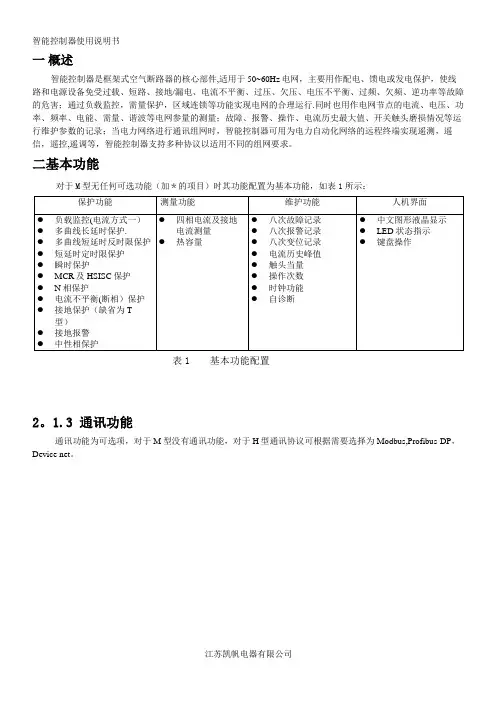
一概述智能控制器是框架式空气断路器的核心部件,适用于50~60Hz电网,主要用作配电、馈电或发电保护,使线路和电源设备免受过载、短路、接地/漏电、电流不平衡、过压、欠压、电压不平衡、过频、欠频、逆功率等故障的危害;通过负载监控,需量保护,区域连锁等功能实现电网的合理运行.同时也用作电网节点的电流、电压、功率、频率、电能、需量、谐波等电网参量的测量;故障、报警、操作、电流历史最大值、开关触头磨损情况等运行维护参数的记录;当电力网络进行通讯组网时,智能控制器可用为电力自动化网络的远程终端实现遥测,遥信,遥控,遥调等,智能控制器支持多种协议以适用不同的组网要求。
二基本功能对于M型无任何可选功能(加*的项目)时其功能配置为基本功能,如表1所示:表1 基本功能配置2。
1.3 通讯功能通讯功能为可选项,对于M型没有通讯功能,对于H型通讯协议可根据需要选择为Modbus,Profibus-DP,Device net。
2。
1.4增选功能选择增选功能为可选项,M型,H型都可以选择增选功能配置,不同增选功能代号与增选功能内容如表2所示.表2 增选功能配置表2。
1。
5 区域连锁及信号单元的选择“区域连锁及信号单元”为可选项,M型、H型都可以选择信号单元的功能配置,当信号单元选择为S2,S3时,控制器具备区域连锁功能.2.2 技术性能2。
2.1 适用环境工作温度:-10℃~+70℃(24h•内平均值不超过+35℃)储存温度:-25℃~+85℃安装地点最湿月的月平均最大相对湿度不超过90%,同时该月的月平均最低温度不超过+25℃,允许由于温度变化产生在产品表面的凝露.污染等级:3级。
(在和断路器装配在一起的情况下)安装类别:Ⅲ。
(在和断路器装配在一起的情况下)2.2.2工作电源由辅助电源和电源互感器同时供电,保证负载很小和短路情况下控制都可以可靠工作。
控制器的供电方式有下面3种方式:a。
电源CT供电额定电流大于等于400A时,一次电流单相不低于0.4In,三相不低于0。

120S自动控制显示器使用说明书©上海英展机电企业有限公司版权所有本产品非供交易用目录安全注意事项 (3)特点介绍 (3)第一章前/后面板规格介绍 (4)1-1前面板 (4)1-2后面板 (4)1-3按键说明 (5)1-4技术参数 (5)1-5查看程序版号 (6)第二章一般常用功能说明 (7)2-1各项设定操作程序 (7)2-2功能设定 (9)2-3错误讯息 (12)2-4内校密码设定说明 (12)第三章校正 (13)3-1荷重元安装 (13)3-2校正参数设定及校正流程 (14)3-3MODBUS校正 (16)3-4规格校正 (17)3-5一般校正 (19)3-6线性校正 (20)3-7数位校正 (22)第四章重量比较程序 (23)4-1重量比较程序之设定说明 (23)4-2重量检测之参数设定 (26)4-3计量信号输出条件 (29)4-4一般投入计量流程图(SQ-01=1) (30)4-5一般排出计量流程图(SQ-01=2) (31)4-6H I,OK,L O输出时机流程图 (32)4-7内建程序投入计量流程图(SQ-01=4) (33)4-8内建程序排出计量流程图(SQ-01=5) (33)4-9保持模式(SQ-01=6) (35)4-9-1 保持模式流程图(SO-01=6) (36)4-9-2 保持模式之Hi,OK,Lo重量比较 (37)4-10自动累加/传送 (37)第五章界面 (38)5-1串行输出/入接口(内建) (38)5-2BCD并列输出接口(OP-02) (46)5-3模拟电流输出接口(OP-03) (48)5-4外部信号输出/输入接口(OP-04,OP-05) (51)第六章维护 (56)6-1所有参数恢复为出厂设定值 (56)6-2功能参数维护 (56)6-2-1 功能设定参数恢复为出厂设定值 (56)6-2-2 清除零点补偿值及去皮值 (56)6-2-3 清除计量设定值 (57)6-2-4 显示零点电压值(mV/V) (57)6-2-5 显示跨距电压值(mV/V) (57)6-3测试模式 (58)6-3-1 7段显示器及各指示符号测试 (59)6-3-2 按键及校正开关测试 (59)6-3-3 A/D内部值显示测试 (59)6-3-4 内建RS-232 串行输出入测试 (59)6-3-5 EEPROM内存测试 (59)6-3-6 Option 适配卡测试 (59)装箱单 (61)附录一七节码字样说明 (62)附录二功能明细表 (63)附录三MODBUS DATA ADDRESS TABLE I (72)附录四MODBUS DATA ADDRESS TABLE II (73)附录五MODBUS输入与输出格式说明 (74)三包事项 (76)产品保修卡 (77)产品合格证 (77)安全注意事项当此控制器被装设于高噪声之场所时,请务必将接地线直接接于背板标示“ ”符号处如有任何因素须将后背板打开时,请务必先将电源连接线与主电源断开当自行安装选配适配卡时,请务必先断电且必须将一黄绿色之接地线固定于背板上(与另外二条接地线锁在一起)开机前请先确认所供给之电压是否在本机之接受范围内AC 100V ~ 240V操作温度为0℃~ +40℃, 储存温度为-10℃~ +55℃特点介绍120S 是一台功能强大且专为重量控制所设计之控制器,其特点如下:小型化之设计♦DIN size 面板尺寸96⨯48 mm方便收纳于控制机台内或镶嵌于控制盘面上♦前面板具泼水防护高性能A/D接口♦0.12μVD高灵敏度♦每秒120次之最高取样速度♦量测范围-0.1 ~ 4.0 mV/V灵活的校正方式♦一般2点校正♦可作5点线性校正♦可直接输入电压值mV/V,无须实际之重量负载♦可读出传感器输出之电压值mV/V,便于日后之维护可调式数字滤波器可有效的抑制现场环境所产生之振动六种重量比较模式可涵盖大部份之应用状况灵活的计量模式,可独立完成简易之系统,或连接PLC达成一复杂之系统♦具有补投料之功能♦泄料手/自动操作♦可设定批次循环次数♦重量及次数累计内建一组RS232C全双工及485通讯接口内建MODBUS (RTU) FORMAT适配卡选配部份♦OP-01 RS422/485/232串行输出/入接口♦OP-02-1 BCD并列输出接口(Open Collector输出)♦OP-02-2 BCD并列输出接口(TTL输出)♦OP-03 16 Bits Analog电流/电压输出接口(0 ~ 20 mA)♦OP-04 控制I/O(4I/4O) + Setpoint In(BCD code)♦OP-05 控制I/O(8I/8O)第一章前/后面板规格介绍∙ 6位数,红色7段显示器,字高0.63∙可作毛重/净重/累计重量/累计次数之切换显示指示符号“ ◄”置零◄: 重量置零指示动作中◄: 不稳定指示毛重◄: 毛重指示净重◄: 净重指示使用者可利用FNC- 06 ~ FNC- 09依需求设定各“ ◄”符号之指示意义,并从随机所附之贴纸中选用适合之小贴纸,贴于“ ◄”符号左边机壳上,方便操作时判读其意义。

多功能控制器用户手册(技术开发文档)文档版本:V1.002发布日期:2021/04/12版权所有© 勤牛创智科技有限公司2021。
保留一切权利。
非经本公司书面许可,任何单位和个人不得擅自摘抄、复制本文档内容的部分或全部,并不得以任何形式传播。
免责申明在法律允许的最大范围内,本手册所描述的产品(含其硬件、软件、固件等)均“按照现状”提供,可能存在瑕疵、错误或故障,勤牛创智不提供任何形式的明示或默示保证,亦不对使用本手册或使用本公司产品导致的任何特殊、偶然或间接的损害进行赔偿。
在使用本产品前详细阅读本使用手册及网上发布的相关技术文档并了解相关信息,确保在充分了解产品相关知识的前提下使用本产品。
本产品的使用者有责任确保遵循相关国家的切实可行的法律法规,确保在勤牛创智机械臂的使用中不存在任何重大危险。
版本修订说明北京勤牛创智科技有限公司地址:北京市海淀区清华东路16 号3号楼中关村能源与安全科技园1603 室网址:目录1. 产品简介....................................................................................................................................................................... - 6 -1.1多功能控制器概述 .......................................................................................................................................... - 6 -1.2控制器外观接口总览...................................................................................................................................... - 6 -2. 控制器接口功能介绍................................................................................................................................................ - 8 -2.1状态指示灯........................................................................................................................................................ - 8 -2.2 OLED屏幕.......................................................................................................................................................... - 8 -2.3导航键 ................................................................................................................................................................. - 8 -2.4第7轴步进电机接口...................................................................................................................................... - 9 -2.5第7轴复位开关接口....................................................................................................................................- 10 -2.6电源输出接口..................................................................................................................................................- 10 -2.7串口通信接口..................................................................................................................................................- 10 -2.8 RS485通信接口 .............................................................................................................................................- 11 -2.9串口通信接口..................................................................................................................................................- 11 -2.10 PWM信号输出接口...................................................................................................................................- 12 -2.11 I/O接口..........................................................................................................................................................- 12 -2.12扩展通信接口...............................................................................................................................................- 13 -2.13 TF卡插槽.......................................................................................................................................................- 13 -3.控制器快速入门..........................................................................................................................................................- 14 -2.1硬件连接...........................................................................................................................................................- 14 -2.2气泵及舵机使用.............................................................................................................................................- 15 -2.3滑轨及传送带使用 ........................................................................................................................................- 16 -2.4执行脱机文件..................................................................................................................................................- 17 -⚫主界面....................................................................................................................................................- 17 - ⚫一级菜单 ...............................................................................................................................................- 17 - ⚫执行“test.gcode”.................................................................................................................................- 18 - ⚫暂停运行 ...............................................................................................................................................- 19 - ⚫停止运行 ...............................................................................................................................................- 19 -2.5脱机文件下载..................................................................................................................................................- 20 -2.6蓝牙通信...........................................................................................................................................................- 22 -⚫示教器蓝牙连接..................................................................................................................................- 22 - ⚫手机APP蓝牙连接............................................................................................................................- 24 - ⚫电脑蓝牙连接......................................................................................................................................- 26 - ⚫修改蓝牙名称与密码 ........................................................................................................................- 28 -2.7 RS485通信 ......................................................................................................................................................- 30 -⚫RS485模式设置..................................................................................................................................- 31 - ⚫配置地址 ...............................................................................................................................................- 32 - ⚫硬件连接 ...............................................................................................................................................- 33 - ⚫多机控制 ...............................................................................................................................................- 33 -2.8 WIFI通信..........................................................................................................................................................- 34 -2.9 串口通信..........................................................................................................................................................- 35 -2.10 I/O引脚触发.................................................................................................................................................- 37 -3.控制器固件升级..........................................................................................................................................................- 38 -3.1控制器固件升级步骤:...............................................................................................................................- 38 -附件一:指令表.............................................................................................................................................................- 39 -1. 产品简介1.1多功能控制器概述多功能控制器(以下简称“控制器”)是Mirobot机械臂的重要配件。

设定日历、时间和日期;1.将拨号盘旋转至时钟/日历(SET CLOCK / CALENDA)位置。
此时,时处闪烁。
2.使用+键或-键进行调节。
注意:上午/下午(A.M/P.M)3.按—》键,分处闪烁。
使用+键或-键进行调节。
4.按—》键,日期处闪烁。
使用+键或-键设定正确的日期。
设定日历;当对浇灌区域有单/双(ODD/EVEN)日期限定的时候,需要进行日历的设定。
1.按《—键,使用+键或-键进行调节。
设定自动程序;一次设定一个程序。
每一个起始时间都可以依次启动该程序中的所有站。
设定起始时间:1.将拨号盘旋转至设定起始时间(SET START TIMES)位置。
程序1闪烁。
每个程序可以设定4个起始时间。
2.按—》键,起始时间1(START 1)处闪烁。
继续按—》键,使用+键或-键进行调节时。
3.按—》键,分处闪烁。
使用+键或-键进行调节。
4.按—》键,返回到程序1(Program 1)。
如果需要设定第二个起始时间,按—》键,使用+键进行调节。
然后,按照设置起始时间1的方法进行设定。
注:如果要关闭一个起始时间,选择该起始时间的编号,按—》键,并使用+键或-键调节调节直到关闭(OFF)状态显示。
设定浇灌日期;这一处可以将浇灌日期设定为每1天—每15天、特定日期或单/双日。
1.将拨号盘旋转至设定浇灌日期(SET WATERING DAYS)位置。
A.间隔浇灌:1.选择每1天—每15天。
屏幕显示的是程序1。
每1天(INTERVAL ONE)闪烁,每天浇灌。
2.按—》键,调节间隔天数。
B.特定日期:1.按—》键,屏幕显示的是程序1中一个星期的第1天。
2.使用-键关闭星期一(MON.),按—》键,进入星期二(TUE.)(第2天/Day 2)3.使用-键关闭一星期中的任意一天,使用+键保留一星期中的任意一天。
C.单/双日:当区域对浇灌有限制时,设定单/双日。
1.按—》键,直到屏幕显示单日(ODD)或双日(EVEN)状态。

AMC1204EVMUser's GuideSBAU178–August2010AMC1204EVM This user's guide describes the characteristics,operation,and use of the AMC1204EVM.TheAMC1204EVM is designed for prototyping and evaluation.A complete circuit description,schematicdiagram,and bill of materials are included.The following related documents are available through the Texas Instruments web site at .Contents1AMC1204EVM Overview (2)1.1Features (2)1.2Introduction (2)2Analog Interface (2)2.1Analog Inputs (2)3Digital Interface (3)4Power-Supplies (4)5EVM Set-up and Operation (4)5.1Isolated Power and Analog Inputs:J1and J4 (4)5.2Device Operation (5)6BOM,Schematic,and Layout (5)6.1Schematic (5)6.2Printed Circuit Board Layout (5)6.3Bill of Materials (6)All trademarks are the property of their respective owners.1 SBAU178–August2010AMC1204EVMCopyright©2010,Texas Instruments IncorporatedIN+IN -ISOGND AMC1204EVM Overview 1AMC1204EVM Overview 1.1FeaturesAMC1204EVM:•Full-featured evaluation module for the AMC1204single-channel,ΔΣmodulator•9-pin sub-D connector for interfacing to the AMC1210digital filter evaluation module •Screw terminals for easy access to analog inputs1.2IntroductionThe AMC1204is a 1-bit modulator with an output buffer separated from the input interface circuitry by a silicon dioxide (SiO 2)isolation barrier.The isolation barrier provides galvanic isolation of up to 4000V PEAK .When used in combination with the AMC1210or other digital filter,the AMC1204can be used to achieve 16-bit analog-to-digital (A/D)conversion with no missing codes.For use in high-resolution measurement applications,an effective accuracy of 14bits can be obtained with a digital filter bandwidth of 20kHz at a modulator rate of 10MHz.Throughout this document,the abbreviation EVM and the term evaluation module are synonymous with the AMC1204EVM.2Analog InterfaceThe analog input to the AMC1204is routed from a two-wire screw terminal screw at J4.This screw terminal gives the user access to the inverting and noninverting inputs of the AMC1204.2.1Analog InputsThe analog input to the AMC1204EVM board consists of simple R/C filter circuits.The input circuit for the AMC1204is shown in Figure 1.Figure 1.AMC1204EVM Schematic:Analog Input Section2AMC1204EVMSBAU178–August 2010Copyright ©2010,Texas Instruments IncorporatedJ2W1W2 Digital Interface3Digital InterfaceThe AMC1204EVM is designed for use with digital filters such as the AMC1210.The output and power for the AMC1204are routed to a 9-pin,female D-type connector.Both the analog and digital power for the AMC1204,as well as the modulator data and clock outputs from the device under test,are routed to J2,as Figure 2illustrates.Figure 2.Power and Digital OutputsConnector J3and jumpers W1and W2can be used to connect up to two AMC1204EVMs together,providing power,CLKIN,and DATA signals to the AMC1210filter chip using a single 9-pin,female,D-type connector.3SBAU178–August 2010AMC1204EVM Copyright ©2010,Texas Instruments IncorporatedPower-Supplies 4Power-SuppliesJ2provides access to the +5VA for the V DD 2supply.All power to the board should be sourced from a well-regulated,linear supply that has current limiting capabilities.Power is to be applied through J2.Table 1describes the pinout for J2.Table 1.J2:Power Supply and Digital OutputsSignal Pin NumberSignalGround12Not used 4.5to 5.5V DD 2supply34Not usedGround 56Optional CLKIN output CLKIN default 78DATA defaultOptional DATA output9For standalone operation,power sources can also be applied via a mating connector to J2,and the digital output data stream can be wired directly to an FPGA or other digital filter module for further processing.Refer to Figure 2or the schematic appended to the end of this document for additional details.5EVM Set-up and OperationThis section describes the general operation of the AMC1204EVM.5.1Isolated Power and Analog Inputs:J1and J4The isolated power input to the AMC1204EVM printed circuit board (PCB)can be applied directly to J1,pins 1and 2.Table 2lists the details of J1.Table 2.J1:Isolated PowerPin NumberSignal DescriptionJ1.1ISOGND Connection to the AMC1204GND1pin J1.25V ISOConnection to the AMC1204VDD1terminalThe analog input to the AMC1204EVM PCB can be applied directly to J4pins 1and 2.Table 3lists the details of J4.Table 3.J4:Analog InputsPin NumberSignal DescriptionJ4.1CHA+Noninverting analog input to the AMC1204J4.2CHA–Inverting input to the AMC12044AMC1204EVMSBAU178–August 2010Copyright ©2010,Texas Instruments Incorporated BOM,Schematic,and Layout 5.2Device OperationOnce the analog and digital power sources are applied to the AMC1204EVM,the digital outputs become active upon the application of an external modulator clock source.The internal reference of the AMC1204 is used as the conversion reference.Additionally,an analog input signal may be applied directly at screw terminal J1.See Figure1and Table3 for more details.The analog input range,(VIN+)–(VIN–),is±320mV.As the input voltage approaches the maximum input level of+320mV,the1s density of the modulatoroutput approaches92%.Likewise,when the input voltage approaches the lower limit of–320mV,the1s density is approximately8%.6BOM,Schematic,and LayoutThis section contains the complete bill of materials,schematic diagram,and PCB layout for theAMC1204EVM.NOTE:Board layouts are not to scale.These are intended to show how the board is laid out;theyare not intended to be used for manufacturing AMC1204EVM PCBs.6.1SchematicThe AMC1204EVM schematic is appended to this document.6.2Printed Circuit Board LayoutFigure3.AMC1204EVM Silk Screen Drawing5 SBAU178–August2010AMC1204EVMCopyright©2010,Texas Instruments IncorporatedBOM,Schematic,and Layout 6.3Bill of MaterialsTable4.AMC1204EVM Bill of MaterialsReference Designator Description Manufacturer Mfr Part Number C1,C6Capacitor,ceramic0.10m F50V X7R10%0603TDK C1608X7R1H104KC2,C7Capacitor,ceramic4.7m F25V X5R0805TDK C2012X5R1E475KC3Capacitor,ceramic330pF50V C0G5%0603TDK C1608C0G1H331JC4,C5Capacitor,ceramic10pF50V C0G0603TDK C1608C0G1H100DD1Not installed——J1,J4Terminal block3.5mm2-pos PCB On Shore ED555/2DSJ2Connector,DB-9female solder cup tin Norcomp172-009-202R001J34-pin,single row header Samtec TSW-104-07-L-SR1,R2Resistor,12.0Ω1/10W1%0603SMD Yageo RC0603FR-0712RLR3Resistor,0..0Ω1/10W5%0603SMD Yageo RC0603JR-070RL W1,W2Not installed,solder short pins1and2——U1IC Delta-Sigma Mod1bit8-SOP TI AMC1204DW6AMC1204EVM SBAU178–August2010Copyright©2010,Texas Instruments IncorporatedEvaluation Board/Kit Important NoticeTexas Instruments(TI)provides the enclosed product(s)under the following conditions:This evaluation board/kit is intended for use for ENGINEERING DEVELOPMENT,DEMONSTRATION,OR EVALUATION PURPOSES ONLY and is not considered by TI to be a finished end-product fit for general consumer use.Persons handling the product(s)must have electronics training and observe good engineering practice standards.As such,the goods being provided are not intended to be complete in terms of required design-,marketing-,and/or manufacturing-related protective considerations, including product safety and environmental measures typically found in end products that incorporate such semiconductor components or circuit boards.This evaluation board/kit does not fall within the scope of the European Union directives regarding electromagnetic compatibility,restricted substances(RoHS),recycling(WEEE),FCC,CE or UL,and therefore may not meet the technical requirements of these directives or other related directives.Should this evaluation board/kit not meet the specifications indicated in the User’s Guide,the board/kit may be returned within30 days from the date of delivery for a full refund.THE FOREGOING WARRANTY IS THE EXCLUSIVE WARRANTY MADE BY SELLER TO BUYER AND IS IN LIEU OF ALL OTHER WARRANTIES,EXPRESSED,IMPLIED,OR STATUTORY,INCLUDING ANY WARRANTY OF MERCHANTABILITY OR FITNESS FOR ANY PARTICULAR PURPOSE.The user assumes all responsibility and liability for proper and safe handling of the goods.Further,the user indemnifies TI from all claims arising from the handling or use of the goods.Due to the open construction of the product,it is the user’s responsibility to take any and all appropriate precautions with regard to electrostatic discharge.EXCEPT TO THE EXTENT OF THE INDEMNITY SET FORTH ABOVE,NEITHER PARTY SHALL BE LIABLE TO THE OTHER FOR ANY INDIRECT,SPECIAL,INCIDENTAL,OR CONSEQUENTIAL DAMAGES.TI currently deals with a variety of customers for products,and therefore our arrangement with the user is not exclusive.TI assumes no liability for applications assistance,customer product design,software performance,or infringement of patents or services described herein.Please read the User’s Guide and,specifically,the Warnings and Restrictions notice in the User’s Guide prior to handling the product.This notice contains important safety information about temperatures and voltages.For additional information on TI’s environmental and/or safety programs,please contact the TI application engineer or visit /esh.No license is granted under any patent right or other intellectual property right of TI covering or relating to any machine,process,or combination in which such TI products or services might be or are used.FCC WarningThis evaluation board/kit is intended for use for ENGINEERING DEVELOPMENT,DEMONSTRATION,OR EVALUATION PURPOSES ONLY and is not considered by TI to be a finished end-product fit for general consumer use.It generates,uses,and can radiate radio frequency energy and has not been tested for compliance with the limits of computing devices pursuant to part15 of FCC rules,which are designed to provide reasonable protection against radio frequency interference.Operation of this equipment in other environments may cause interference with radio communications,in which case the user at his own expense will be required to take whatever measures may be required to correct this interference.EVM Warnings and RestrictionsIt is important to operate this EVM within the input voltage range of0V to5V and the output voltage range of0V to5V.Exceeding the specified input range may cause unexpected operation and/or irreversible damage to the EVM.If there are questions concerning the input range,please contact a TI field representative prior to connecting the input power.Applying loads outside of the specified output range may result in unintended operation and/or possible permanent damage to the EVM.Please consult the EVM User's Guide prior to connecting any load to the EVM output.If there is uncertainty as to the load specification,please contact a TI field representative.During normal operation,some circuit components may have case temperatures greater than+30°C.The EVM is designed to operate properly with certain components above+30°C as long as the input and output ranges are maintained.These components include but are not limited to linear regulators,switching transistors,pass transistors,and current sense resistors.These types of devices can be identified using the EVM schematic located in the EVM User's Guide.When placing measurement probes near these devices during operation,please be aware that these devices may be very warm to the touch.Mailing Address:Texas Instruments,Post Office Box655303,Dallas,Texas75265Copyright©2010,Texas Instruments IncorporatedIMPORTANT NOTICETexas Instruments Incorporated and its subsidiaries(TI)reserve the right to make corrections,modifications,enhancements,improvements, and other changes to its products and services at any time and to discontinue any product or service without notice.Customers should obtain the latest relevant information before placing orders and should verify that such information is current and complete.All products are sold subject to TI’s terms and conditions of sale supplied at the time of order acknowledgment.TI warrants performance of its hardware products to the specifications applicable at the time of sale in accordance with TI’s standard warranty.Testing and other quality control techniques are used to the extent TI deems necessary to support this warranty.Except where mandated by government requirements,testing of all parameters of each product is not necessarily performed.TI assumes no liability for applications assistance or customer product design.Customers are responsible for their products and applications using TI components.To minimize the risks associated with customer products and applications,customers should provide adequate design and operating safeguards.TI does not warrant or represent that any license,either express or implied,is granted under any TI patent right,copyright,mask work right, or other TI intellectual property right relating to any combination,machine,or process in which TI products or services are rmation published by TI regarding third-party products or services does not constitute a license from TI to use such products or services or a warranty or endorsement e of such information may require a license from a third party under the patents or other intellectual property of the third party,or a license from TI under the patents or other intellectual property of TI.Reproduction of TI information in TI data books or data sheets is permissible only if reproduction is without alteration and is accompanied by all associated warranties,conditions,limitations,and notices.Reproduction of this information with alteration is an unfair and deceptive business practice.TI is not responsible or liable for such altered rmation of third parties may be subject to additional restrictions.Resale of TI products or services with statements different from or beyond the parameters stated by TI for that product or service voids all express and any implied warranties for the associated TI product or service and is an unfair and deceptive business practice.TI is not responsible or liable for any such statements.TI products are not authorized for use in safety-critical applications(such as life support)where a failure of the TI product would reasonably be expected to cause severe personal injury or death,unless officers of the parties have executed an agreement specifically governing such use.Buyers represent that they have all necessary expertise in the safety and regulatory ramifications of their applications,and acknowledge and agree that they are solely responsible for all legal,regulatory and safety-related requirements concerning their products and any use of TI products in such safety-critical applications,notwithstanding any applications-related information or support that may be provided by TI.Further,Buyers must fully indemnify TI and its representatives against any damages arising out of the use of TI products in such safety-critical applications.TI products are neither designed nor intended for use in military/aerospace applications or environments unless the TI products are specifically designated by TI as military-grade or"enhanced plastic."Only products designated by TI as military-grade meet military specifications.Buyers acknowledge and agree that any such use of TI products which TI has not designated as military-grade is solely at the Buyer's risk,and that they are solely responsible for compliance with all legal and regulatory requirements in connection with such use. TI products are neither designed nor intended for use in automotive applications or environments unless the specific TI products are designated by TI as compliant with ISO/TS16949requirements.Buyers acknowledge and agree that,if they use any non-designated products in automotive applications,TI will not be responsible for any failure to meet such requirements.Following are URLs where you can obtain information on other Texas Instruments products and application solutions:Products ApplicationsAmplifiers Audio /audioData Converters Automotive /automotiveDLP®Products Communications and /communicationsTelecomDSP Computers and /computersPeripheralsClocks and Timers /clocks Consumer Electronics /consumer-appsInterface Energy /energyLogic Industrial /industrialPower Mgmt Medical /medicalMicrocontrollers Security /securityRFID Space,Avionics&/space-avionics-defenseDefenseRF/IF and ZigBee®Solutions /lprf Video and Imaging /videoWireless /wireless-appsMailing Address:Texas Instruments,Post Office Box655303,Dallas,Texas75265Copyright©2010,Texas Instruments IncorporatedAMC1204EVM。
无极调速控制器1204-404说明书
1、接线
接线时断开电源,按调速器面板所标接线,面板右边两对接线柱,上面一对接电枢,下面一对接电机励磁绕组,并分别以红色、橙色导线区分。
2、开机
开机后,看转子转动方向是否正确,由转子向电机方向看,顺时针方向为正确,若反时针转,可将电枢(或励磁)的两根线对调。
注意:每次启动前都要把调压器左旋到零位,即保证电枢电流从零开始往上调,以避免启动电流过大烧断保险丝。
面板左边有两个3A保险丝,左边一个为电枢电路保险,右边一个为电源保险。
3、升速
接通电源开关,电源指示灯亮,微动调压器,电流表即有指示,负载较小时,转子即会转动。
升速时必须平滑地转动调压器旋钮,开始升得较慢,调压器转到某一位置后升速较快,这时必须注意要更平稳、缓慢地转动调压器,以保证瞬时电流不致过大。
降速时,同样要注意平缓,在高速状态停机,应通过平稳降速过程再切断电源,否则电机承受冲击较大。
中文使用说明书N B系列自启动控制器NB30 NB31NB36 NB65十六、损坏后应急处理办法当确定是控制器损坏而不能正常工作,但又要机组应急工作,此时可以通过下面办法应急处理,但必须强调的是此办法只是应急,不可长期采用此办法工作,因为控制器的损坏将不能对机组在真正出现故障的情况下进行监测报警停车,因此在非紧急情况下请及时取寄回厂家修理。
处理办法:步骤1、断开控制器电源;步骤2、用1-1.5 mm2的电线将控制器背面电源负极和BO2(出厂预设BO2为油阀)端子连接;步骤3、给控制器通电;步骤4、准备启动机组,用1.5mm2的电线短接控制器背面电源负极和BO1(出厂预设BO1为启动马达)端子,此时启动马达工作,一旦机组启动成功,请迅速断开控制器背面的电源负极和BO1连接线,使启动马达脱开,否则启动马达一直跟着发动机旋转会被损坏。
启动机组步骤完成,如果控制器模块能显示,还是可以查看各参数,注意此时已没有报警功能。
需要停机时,把模块背面电源负极和BO2断开即可。
注意:在应急情况下,发电机组不用时请关闭控制器模块电源,否则会消耗电目录一、概述 2二、控制器的操作界面和开孔尺寸、外围接线图 3-6三、控制器使用前的准备工作7四、使用操作简要说明7-10五、显示屏参数查看 11六、参数设置操作12七、电脑通讯连接的基本方法 12八、警告与停车故障说明 12九、电压相序错误 12十、主要故障排除说明13 十一、故障排除指引及措施14-15 十二、控制器出厂默认表 16-19 十三、控制器辅助输入功能中英文简明对照表20 十四、控制器辅助输出功能中英文简明对照表21-23 十五、功能对照表23 十六、损坏后应急处理办法24一.概述本公司生产的NB系列自启动控制器包括NB30、NB31、NB36、NB65等多款型号,它们能对各种柴油、汽油、燃气等发电机组的重要参数进行检测、监控和保护,能满足使用者对各种发电机组的需求。
深圳市爱庞德新能源科技有限公司I-P-SMART2-40A/50A/60A目录1 注意事项 (2)2 安全说明 (2)3 设备开封检查 (5)4 MPPT控制器安装 (6)5 MPPT控制器连接 (7)6 LED\LCD和功能键说明 (10)7 MPPT控制器参数设置 (12)8 MPPT控制器与PC的连接 (13)9 MPPT控制器技术参数 (18)10 维护和清洁................................................................................... . (20)11 储存和废弃处理 (21)12 故障处理与保修 (21)1、注意事项本手册介绍了有关我司SMART 第二代MPPT 太阳能充电控制器的相关操作。
1.1 有效性本手册适用于我司第二代的MPPT 太阳能充电控制器。
1.2 目标群体本手册适用于安装者和操作者。
1.3 在安装和操作控制器前,请先阅读并且请务必妥善保管本说明书,以便查阅。
1.4 符号说明以下是出现在本使用手册的标志类型的说明:2、安全说明2.1 安全注意事项警告! •本控制器输入电压范围大,如不谨慎操作,会导致人身伤害; •充电控制器上的所有工作必须由技术人员进行; •该装置不能由儿童或缺少身体感官能力者和心理能力差者或缺乏经验和知识者操作; •远离儿童、确保儿童不要接触。
警告! “警告”表示,如果不避免,可能会导致机器故障或事故。
危险!“危险”表示,如果不避免,可能会导致机器故障或事故。
注意! 为了有效的操作好本设备,请认真阅读设备操作指示。
2.2 标志说明● 本节给出了所有的设备标签上所显示标志说明。
标志 说明有触电的危险;在断开五分钟后存储在电容器中的能量将仍然存在着,在断开后5分钟不要触碰内部元器件。
没有自我维修的部件在机柜内,不要试图取下盖子; 只有专业人士才能操作和维护设备;操作时请使用绝缘的工具,以降低危害风险。
DMX512 通道数1024电脑灯的配接数量96电脑灯重新配接地址码支持灯具水平垂直交换支持灯具通道反倒输出支持灯具通道滑步模式切换支持每台电脑灯最多可用控制通道40主通道+40微调通道灯库支持珍珠R20灯库可保存的场景数量60可同时运行的场景数量10多步场景的总步数600场景的时间控制淡入、淡出、LTP滑步每个场景可存储图形数量 5推杆启动场景并进行调光支持互锁场景支持点控场景支持图形生成器可生成Dimmer, P/T, RGB, CMY, Color, Gobo,Iris, Focus图形可同时运行图形数量 5主控推杆全局、重演、灯具立即黑场支持转盘调整通道数值支持推杆调整通道数值支持推杆调光支持U盘读取支持FAT32格式插座引入脚编号电缆芯线1 屏蔽网层2 信号负端3 信号正端面板图该控台主要由若干个区组成:灯具区:由16个灯具键、16根预置推杆和6个灯具换页键组成。
6个灯具页,每页可配接灯具16台,总共可配接96台。
16根预置推杆可对下方相应的灯具进行调光,也可对其上方与之对应的属性进行修改。
其功能的切换键位于预置推杆的右侧双灯的按键,当绿灯亮时预置推杆用于调光,菜单的起始页也会提示“推杆模式=亮度等级”,当红灯亮时预置推杆用于属性的修改,菜单起始页也会提示“推杆模式=属性”。
重演区:由10个重演按键、10个素材按键、10根重演推杆、5个翻页键、3根主控推杆和1个黑场键组成。
重演翻页键有A、B键和1、2、3键,组合起来有6页,每页有10根重演推杆,总共可存储60个场景。
每根重演推杆上方都有一个蓝色的场景键。
重演推杆:用于执行场景的输出与关闭。
如果当前推杆储存有场景,将其从0的位置推起则会输出该场景,并且该场景的调光输出由推杆控制。
每根重演推杆在同一时间只能控制一个场景,所以此控台同时最多输出10个场景。
场景键:在场景编辑菜单下用于配合场景的编辑任务。
在初始菜单下,可用其点控场景,当我们按下场景键时,就会输出其对应的场景。