iXinc_C6_Controller控制器感应探头
- 格式:pdf
- 大小:46.89 KB
- 文档页数:1

GM8006C智能控制仪器使用说明书山东注意:使用本仪表前请认真阅读本说明书a:仪表电源进线必须接触良好,不允许出现:受潮生锈,接触不好现象。
b:仪表控制柜接地线必须单独接大地。
c:传感器屏蔽线必须单独接大地。
仪表控制柜接地传感器屏蔽线接地和强电电器接地不能共用一个接地。
d:变频器控制柜必须接大地。
e:变频器控制的电机必须接大地。
f:供电电源严禁与大功率或启动频繁的电器共相。
目录一、系统简介、功能及指标 (1)二、显示及功能键操作说明 (2)三、操作实例说明 (2)四、校零、标秤及其它 (6)五、报警说明 (7)六、启动仪表 (7)七、仪表后板接线示意 (7)八、控制器尺寸 (8)九、参数简表 (9)表一一级修改参数显示参数Y03 给定值<10000KG/分默认值200 E00 K值xxxx.xxY04 预控值1 <255 默认值50 Y00 AD值0--65536Y05 零点<65535 默认值4000 Y01 速度值<4000Y06 P 值<100 默认值.20 Y02 总产量xxxxxx.xx吨Y07 I 值<100 默认值10 Y03 给定值<10000KG/分Y08 预控值2 <255 默认值0 Y04 预控值1 <255Y09 上限零点<255 默认值20 Y05 零点<30000二级修改参数E00 K值xxxx.xx 默认值500.00 E01 周期< 255秒默认值60E02 校零时间>20秒,< 255秒默认值20E03 失控停机时间<255秒默认值0E04 自动校零时间<255分默认值0E05 停机延迟时间<255秒默认值0E06 控制步距<100 默认值10E07 远程输入给定单位1,KG; 0,吨默认值 1E08 启动是否校零0, 校零,1不校零默认值 1E09 秤体选择0,1,2,3分别对应恒速,调速,失重,断续秤默认值0E10 启动选择0,本机;1,远程;2,485数默认值0E11 给定选择0,本机;1,远程;2,485 默认值0E12 程控放大倍数0,1,2,3分别对应1倍2倍4倍8倍默认值0E13 计量单位选择1,KG; 0,吨默认值 1E14 波特率0,1,2,3 默认值0E15 停机是否累计0不累计; 1累计默认值0E16 报警系数<.99 默认值.20E17 累计输出脉冲<10000KG 默认值1000E18 日期年,月,日E19 时间时,分,秒E20 远程给定输入最大值<10000KG/分默认值500E21 远程流量输出最大值<10000KG/分默认值500E22 远程输入给定上限10-20mA对应65536 默认值65535 E23 远程输入给定下限0--4mA对应0-xxxxx 默认值0E24 流量输出上限1023对应10-20mA 默认值977E25 流量输出下限0xxx对应0-4 mA 默认值195E26 自动停机 1 到给定自动停机,0 反之默认值0E27 设备地址<256 默认值0E28 计量选择0,启动开始计量1端口控制开始计量默认值0E29GM8006C智能控制器操作使用说明一 :简介GM8006C系列称重控制器采用国际最新技术研制和生产的新一代配料称仪表,是静态,动态计量和配料的专用智能仪表。

-------EasyController易众系列------硬件手册版权声明本手册供用户参考、查阅关于EasyController易众系列控制器硬件的相关信息,其中的文字、图示、标志、商标、专利型号均受《中华人民共和国专利法》、《中华人民共和国商标法》以及相关国内外公约中专利权、商标权的法律保护。
为北京易斯路电子有限公司专署持有。
任何团体和个人不得在未取得北京易斯路电子有限公司授权的情况下,对本手册进行转载、复制和发布,否则易斯路公司将依法追究其法律责任。
本手册所涉及到的EasyController易众系列控制器硬件的相关信息,均经过我公司技术人员的严格审定和校验,但无法避免与实际物品没有误差。
另外我们会根据设备的改进完善情况,定期对手册进行修订和改版,请注意手册的版本信息,恕我们不再另行通知。
EasyController该字样和商标为北京易斯路电子有限公司注册,受完全的法律保护。
手册中涉及到的其它商标属于它们各自的拥有者。
版本信息文件名称EasyController易众系列硬件手册当前版本V3.0完成日期2018-10-18历史记录版本日期V1.02010-12-18前言感谢您使用本公司EasyController易众控制器。
EasyController易众控制器是基于ST公司ARM处理器架构的32位微控制器,在一块芯片中集成了微控制器、微处理器和数字信号处理器。
具有512KB的嵌入式Flash和多种创新的片上外设,提升了系统总体性能。
EasyController易众控制器由输入单元、控制单元、输出单元等多个系统单元组成,使得整个机器控制系统实现了尺寸最小化,工程造价经济化。
本控制器可应用于工程车的测量、输入、输出控制,控制器给用户一个可编程的控制平台,用户可根据实际的需要进行编程控制。
应用领域:伐木机械道路维护建筑机械破碎设备工业设备农业机械自动化应用凿岩机械在使用EasyController易众系列控制器之前,请您仔细阅读本使用说明书,并请妥善保存。

EAN 4007841 033446Article number 033446infrared sensor360°max. 20 m2000 W max. (LED-ready)IP54 2 - 1000 lux 5 sec - 15 min manual override 4h ideal 2,5 - 4 m Teach mode energy savingFunction descriptionHigher, further, faster. Infrared presence detector IS 3360 for indoors and out, ideal for watching over high spaces and large areas, such as multi-storey and underground car parks, installation height up to 4 m, 360° angle of coverage, reach 20 m max. (tangential), large terminal compartment for easy installation, heavy-duty relay for high switching capacity. Available either in round or square surface-mounted, concealed or In-ceiling installation.Technical specificationsDimensions (Ø x H)126 x 65 mm With motion detector Yes Manufacturer's Warranty 5 yearsSettings via Remote control, Potentiometers, Smart Remote With remote control NoVersion COM1 - surface, rd. white PU1, EAN 4007841033446TypeMotion and Presence Detector Application, placeOutdoors, IndoorsApplication, roomproduction facilities, recreation room, changing room, function room / ancillary room, sports hall,reception / lobby, stairwell, WC / washroom, multi-storey /underground car park, outdoors, warehouse, Indoors Colour white Colour, RAL9003LED lamps > 8 W 600 W Capacitive load in μF 176 µFTechnology, sensors passive infrared, Light sensor Mounting height 2,50 – 4,00 m Mounting height max.4,00 m Optimum mounting height 2,8 m Detection angle 360 °Angle of aperture 180 °Sneak-by guardYes Capability of masking out individual segmentsYes Electronic scalability No Mechanical scalability NoReach, radial Ø 8 m (50 m²)Reach, tangential Ø 40 m (1257 m²)Reach, presence Ø 3 m (7 m²)Switching zones1416 switching zoneshttps://www.steinel.deEAN 4007841 033446Article number 033446 Technical specificationsIncludes corner wall mount NoInstallation site ceilingInstallation Surface wiring, Ceiling IP-rating IP54Ambient temperature-20 – 50 °CMaterial PlasticMains power supply220 – 240 V / 50 – 60 Hz Switching output 1, resistive2000 WSwitching output 1, number ofLEDs / fluorescent lamps8 pcs.Fluorescent lamps, electronic ballast1500 WFluorescent lamps, uncorrected1000 VAFluorescent lamps, series-corrected400 VAFluorescent lamps, parallel-corrected400 VASwitching output 1, low-voltagehalogen lamps2000 VALED lamps < 2 W100 WLED lamps > 2 W < 8 W300 W FunctionsNormal / test mode, Manual ON /ON-OFFTwilight setting 2 – 1000 lxTime setting 5 s – 15 Min.Basic light level function NoMain light adjustable NoTwilight setting TEACH YesConstant-lighting control NoInterconnection YesType of interconnection Master/master Interconnection via CableInterconnection, number max. 10 sensorsAccessoriesEAN 4007841 009151Remote control Smart RemoteEAN 4007841 559410Service remote control RC8EAN 4007841 056735Black cover for IR-sensorshttps://www.steinel.deEAN 4007841 033446Article number 033446Detection Zone Dimension DrawingCircuit diagramhttps://www.steinel.deEAN 4007841 033446Article number 033446Circuit diagram for interconnecting several sensorsConnection using two-circuit switch for manual and automatic operation Circuit diagram Connection via a changeover switch for continuous and automatic operationhttps://www.steinel.de。
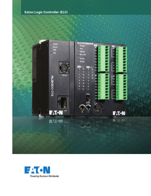
Eaton Logic Controller (ELC)The Eaton Logic Controller.Compact, modular, and ready tocommunicate. It’s the cost-effectivesolution to machine control.The right amount of I/O.Why pay for functionality you don’t need? Why be trapped with functionality you can’t scale to meet changing needs? Eaton is changing everything with the ELC.At less than half the size of most PLCs, the ELC is an ideal solution when space is at a premium and specialized I/O needs present themselves.Space saving. Cost saving.This space-saving design is as perfectly at home in asmall machine control station as it is in an MCC and other enclosed applications where space is critical. Reduced space also means smaller control cabinets and panels, or more capability in the same amount of space. However you look at it, the ELC means value.Half the size of most PLCs, the ELC puts the right amount of I/O right where you need it.ELC Controller and Expansion Modules.ELC Programming SoftwareProgram on your PC and download to the ELC through a serial cable or over Ethernet. Make online changes, monitor and remote control the run/stop operation. Software wizards simplify the programming process.eaton corporation Programmable Logic Controller 3Machine spaceis measured in inches.The ELC is measuredthe same way.eaton corporation Programmable Logic Controller 5ELC’s value added differences 5 controller styles: •PB Base Model— 14 I/O (8i/6o)Over 130 instructions provide all the power you need. Two serial ports for master/slave communications.•PC Clock/Calendar Model— 12 I/O (8i/4o)Same as the PB model, plus clock/calendar, twice theprogram steps, distributed I/O, and retentive data storage.•PA Analog Model— 10 I/O (6i/4o)Same as the PC model, plus embedded analog I/O.•PH High-Speed Model— 12 I/O (8i/4o)Same as the PC model, plus the ability to capture or output 100 kHz pulses.•PV Advanced Model— 28 I/O (16i/12o)Almost 10 times faster than the other ELC controllers, high speed I/O to 200 kHz, and additional advanced features. Add left side expansion modules for master communicationson networks such as Ethernet and DeviceNet ™.More Controller Features•High-speed pulse capture and high-speed pulse output on all controllers.•Broad selection of AC/DC in, relay/transistor and high current output modules.•Large selection of analog In/Out in various I/O counts per module.• 2 Modbus ®(ASCII / RTU) serial ports: 1 slave only, 1 master/slave.•Over 200 instructions to choose from: Floating point math, communications, 16- and 32-bit math, logical, blockmove, block compare, retentive data storage, conversion, time base from clock/calendar.ELC benefits solve applications:Size —large PLC features in a 1" package. Half the size of competitive offerings. ELC can retrofit more I/O in the same space or allow more costsavings by reducing cabinet size.Flexibility —ELC controllers expand from 10 to hundreds of I/O points. Expand with up to 16 modules (no more than 8 analog/specialty modules).•Add only the amount of I/O you need. Choose I/O counts as small as 2 points and as large as 16 points per module.•DIN-rail mounting lets you add as many modules as needed by snapping them into mating connectors.Large PLC Features —Multiple communications ports,distributed I/O capability, high speed counters, high speed pulse outputs, interrupts, timer resolution to 1ms, PIDs, plus much more.Software —ELCSoft programs in standard ladder or sequential function chart programming.•Display registers “in use” and modules attached to the ELC.•Monitor runtime applications and enter/modify register values.•Wizards aid programming of ELC Link for distributed I/O, standard communications, high speed counters,pulse outputs, positioning, interrupts, PIDs, and extension module setup.Communications —Connecting to networks is easy on Modbus ®, Modbus TCP , DeviceNet ™, and Profibus.No racks requiredA DIN-rail lets you add as many modules as desired. Just snap on, and slide into place. All connections are done automatically. Built-in displayAn integral LED display on some models provides user-assigned process monitoring, error messages, alarms, display counts and more.ELC Features and SpecificationsELC Controller Features and Specificationscontroller eLc-pB14nnDr/Dt eLc-pa10aaDr/Dt eLc-pc12nnar/Dr/Dt eLc-pH12nnDt eLc-pV28nnDr/Dt Dimensions WxHxD (mm) 25.2 x 90 x 60 37.4 x 90 x 60 70 x 90 x 60 Maximum I/O—Expandable up to 16 expansion modules (maximum of 8 analog/specialty modules)I/O Type—Embedded 14 (8 DI/6DO) 10 (4DI/2DO/2AI/2AO) 12 (8 DI/4 DO) 28 (16DI/12DO) DC In Sink/Source YesExecution Speed Basic instructions—2 µs minimum 0.24 µs minimum Program Language Instructions + Ladder Logic + SFCProgram Capacity (steps) 3792792015,872Data Memory Capacity (bits) 12804096Data Memory Capacity (words) 744500010,000 Index Registers 2816File Memory Capacity (words) None1600 Words 10,000 Words Retentive Storage YesCommands Basic/Advanced 32/107 32/168 32/193 Floating Point YesSFC Commands (steps) 1281024Timers Qty 128244 standard with additional timers for subroutine and retentive applicationsTimers Resolution1–100msCounters Qty 128 250 253High Speed Counters (See Note)Up to 4Up to 6Up to 8Up to 8Max High Speed Counting (See Note) 2 at 20 kHz 1 at 30 kHz 1 at 100 kHz 2 at 200 kHz Pulse Output 2 channels, 10 kHz Max 2 channels, 50 kHz Max 100 kHz 200 kHzPID YesMaster Control Loop 8 LoopsSubroutines 64 Subroutines 256 SubroutinesFor/Next Loops YesInterrupts 61522Real-time Clock / Calendar No Built-inPassword Security YesDiagnostic Relays YesDiagnostic Word Registers YesSpecialty Expansion Modules (Analog In/Analog Out/TC/RTD/PT) Up to a maximum of 8Serial Ports 2 Modbus (ASCII/RTU) 1=Slave (RS-232)/1=Master-Slave (RS-485)Remote I/O No With 16 other devices With 32 other devices Run Time Editing No YesRun / Stop Switch YesRemovable Terminal Strips YesSpecial Features —2, 7-Segment Displays 2 Potentiometers 2 PotentiometersHigh-speed, left side bus Note: High speed counter inputs can be used for different types of 32-bit counting, such as single-ended, single-phase two inputs, and quadrature.Therefore, all high speed counters may not be used at the same time. Please refer to the ELC Systems Manual, MN05003003E, for details.controller Module inputs outputs110 Vac 24 Vdcsink/sourceanalog relay24 Vdcsinking analogELC-PB14NNDR—8—6——ELC-PB14NNDT—8——6—ELC-PC12NNAR8——4——ELC-PC12NNDR—8—4——ELC-PC12NNDT—8——4—ELC-PA10AADR—422—2 ELC-PA10AADT—42—22 ELC-PH12NNDT—8——4—ELC-PV28NNDR—16—12——ELC-PV28NNDT—16——12—eaton corporation Programmable Logic Controller6ELC Expansion Module FeaturesDigital i/o Model power input Unit output Unitpoint type point typeDimensions WxHxD (mm) 25.2 x 90 x 60ELC-EX08NNAN24 Vdc 8110 Vac0—ELC-EX08NNDN8DC Sink or Source 0—ELC-EX08NNNR08Relay ELC-EX08NNNT08Transistor ELC-EX06NNNI06High Current Relay ELC-EX08NNDR44Relay ELC-EX16NNDR88ELC-EX08NNDT44Transistor ELC-EX16NNDT88analog i/o Model power input Unit output Unitpoint type point typeDimensions WxHxD (mm) 25.2 x 90 x 60ELC-AN02NANN24 Vdc 0—20~+20mA OV~+10VELC-AN04NANN04ELC-AN06AANN4–20mA~+20mA–10V~+10V 2ELC-AN04ANNN40—ELC-PT04ANNN4Platinum Temp.0ELC-TC04ANNN4Thermocouple0 Electrical SpecificationsInput Voltage Requirements ELC: 24 Vdc (–15%~+20%) (with DC input reverse polarity protection), Expansion Unit: supplied by the ELCPower Consumption Typically 3–6WInsulation Resistance>5 MΩ at 500 Vdc (Between all inputs/outputs and earth)Noise Immunity ESD: 8 kV Air Discharge EFT: Power Line 2 kV, Digital I/O: 1 kV, Analog & Communication I/O: 1 kV Damped-Oscillatory Wave: Power Line: 1 kV, Digital I/O: 1 kV RS: 26 MHz–1 GHz, 10 V/mTemperature Operation: 0ºC~55ºC (Temperature), 50~95% (Humidity), Pollution degree 2; Storage: –40ºC~70ºC (Temperature), 5~95% (Humidity)Vibration/ShockResistanceStandard: IEC1131-2, IEC 68-2-6 (TEST Fc)/IEC1131-2 & IEC 68-2-27 (TEST Ea)Certifications C-Tick, cULus, CE, Class I Div 2 Groups A, B, C, DELC Accessoriescatalog number DescriptionELC-PS0124 Watt, 1 Amp Power SupplyELC-PS0248 Watt, 2 Amp Power SupplyELC-HHP Hand-Held Programmer (includes cable)ELC-CBPCELC1Cable to connect a PC or ELC-GP unit to ELC, 1 meter with right angle connector (DB9 pin female to 8-pin DIN)ELC-CBPCELC3Cable to Connect a PC or ELC-GP unit to ELC, 3 meters (DB9 pin female to 8-pin DIN)ELC-CBPCGP3Cable to Connect a PC to an ELC-GP unit, 3 meters (DB9 pin female to DB9 pin female)ELC-GPXFERMOD Program transfer module for ELC-GP unitsELC-ACPGMXFR Program transfer module for ELC controllersELC-ACCOVER Plate mount for specialty modules, qty. 10ELCSTARTKIT1ELC Starter Kit (includes ECL-PA10AADT, ELC-PS01, ELC-GP04, ELC-CBPCELC3,ELC-CBPCGP3, ELCSoft, ELCSoft GP)ELC-COENETM10/100 Ethernet Module, need ELC-PV, ModbusTCP, P-P, for use with ELC-PV onlyELC-CODNETM DeviceNet Module, need ELC-PV, Scanner, Poll, CC, COS, BS, for use with ELC-PV onlyELC-COPBDP Profibus DP Slave ModuleELC-CODNET DeviceNet Slave ModuleELC-485APTR RS-485 Easy Connect Adapter, DB9, RJ-12, 2-Pin Connections to RS-485ELC-MC01Motion Control, 1 Axis Module (Up to 8 Modules per Controller)eaton corporation Programmable Logic Controller7Eaton Corporation Electrical Sector1111 Superior Ave. Cleveland, OH 44114United States877-ETN-CARE (877-386-2273) © 2010 Eaton CorporationAll Rights ReservedPrinted in USAPublication No. BR05003001E / MZ588 March 2010PowerChain Management is a registered trademark of Eaton Corporation.All other trademarks are property of theirrespective owners.Eaton’s Electrical Sectoris a global leader in power distribution, power quality, control and automation, and monitoring products. When combined with Eaton’s full-scale engineering services, these products provide customer-driven PowerChain™ solutions to serve the power system needs of the data center, industrial, institutional, public sector, utility, commercial, residential, IT, mission critical, alternative energy and OEM markets worldwide. PowerChain solutions help enterprises achieve sustainable and competitive advantages through proactive management of the power system as a strategic, integrated asset throughout its life cycle, resulting in enhanced safety, greater reliability and energy efficiency. For more information, visit /electrical.。

|DSU9H & DSU9X MODELSSIL3 PLe INCREMENTAL ENCODERS SPECIFICATIONSFeatures•Usable up to SIL3 and Cat.4 / PLe according to IEC 61508 / EN ISO 13849•Suitable for safe motor feedback according to IEC 61800-5-2•E specially designed for heavy-duty applications (steel, paper, wood,mills, cranes…) Compact and robust design. Excellent resistance to shock and vibration•Stainless steel version available (DSU9X)•90mm encoder, 30mm standard through shaft, PE E K reduction hub available•High protection level: IP66 (DSU9X), IP65 (DSU9H)•High temperature performance –20°C to +85°C •Power supply 5Vdc or 11/30Vdc•Digital TTL/RS422 or HTL Push-pull or sine/cosine 1Vpp output •Available resolution up to 2048 ppr•Connector or cable output – side orientation •Adapted anti-rotation systemIntroductionApplications•Industrial automation•Automated guided vehicles•Mills for lumber, steel and other metals •Printing and packaging equipment •Food processing equipment •Forming and die pressesDSU9XWhen an automation system requires a high degree of risk mitigation of failure modes, often times Functional Safety equipment can be a part of the solution. Sensata | BEI Sensors offers a wide range of Functional Safety encoders to fit most any application or electrical interface requirement. Rated at SIL3 (PLe), these encoders allow safe operation in set-up, production and maintenance modes, significantly reducing operational risks. All encoders have the option of a Digital HTL or TTL operation as an alternative to the Sine/Cosine outputs found on most Functional Safety encoders. This makes them a compatible replacement for existing encoders when migrating to a higher safety level of operation. DSU9H & DSU9X offer 30 mm standard through shaft models with optional reduction sleeves for mounting on smaller diameter shafts. The encoder body is 90mm in diameter, available in aluminum or stainless steel.(A)Continuous max. speed – ½ max. load – according to ISO 281: 1990, L10(B)Device must be supplied by a Class 2, LPS or SELV limited energy source.(C) UL listed:Electrical ConnectionsNote: All connections are UL certified, except G3 and GP RESOLUTIONS1024 2048DSU9H – radial cable and 20mm reduction hubDSU9X- radial M23 connector - IP66 optionCOUPLING INTERFACE Stator coupling kit M9445/045Tether arm kit M9445/046For a safe installation according to the required safety level needed in the application, refer to the user safety User Manual.The safety User Manual provides the technical information (drawings, electrical data, etc...) for a safe integration.A quick installation guide is provided with each encoder for use by the technician who installs the device on the equipment.GENERAL NOTESORDERING OPTIONSContact the factory for special versions, ex: resolution, connection, flange...* Parts mounted on encoder and fasteners included in the encoder box.AGENCY APPROVALS & CERTIFICATIONSBEI Sensors SASSensata TechnologiesEspace Européen de l’Entreprise9, rue de CopenhagueB.P. 70044 SchiltigheimF 67013 Strasbourg CedexTélFaxMailWeb: +33 (0)3 88 20 80 80: +33 (0)3 88 20 87 87:****************************: Americas+1 (800) 350 2727*******************Europe, Middle East & Africa +33 (3) 88 20 8080****************************Asia Pacific*************************.com China +86 (21) 2306 1500Japan +81 (45) 277 7117Korea +82 (31) 601 2004India +91 (80) 67920890Rest of Asia +886 (2) 27602006 ext 2808Page 7CONTACT USSensata Technologies, Inc. (“Sensata”) data sheets are solely intended to assist designers (“Buyers”) who are developing systems that incorporate Sensata products (also referred to herein as “components”). Buyer understands and agrees that Buyer remains responsible for using its independent analysis, evaluation and judgment in designing Buyer’s systems and products. Sensata data sheets have been created using standard laboratory conditions and engineering practices. Sensata has not conducted any testing other than that specifically described in the published documentation for a particular data sheet. Sensata may make corrections, enhancements, improvements and other changes to its data sheets or components without notice.Buyers are authorized to use Sensata data sheets with the Sensata component(s) identified in each particular data sheet. HOWEVER, NO OTHER LICENSE, EXPRESS OR IMPLIED, BY ESTOPPEL OR OTHERWISE TO ANY OTHER SENSATA INTELLECTUAL PROPERTY RIGHT, AND NO LICENSE TO ANY THIRD PARTY TECHNOLOGY OR INTELLECTUAL PROPERTY RIGHT, IS GRANTED HEREIN. SENSATA DATA SHEETS ARE PROVIDED “AS IS”. SENSATA MAKES NO WARRANTIES OR REPRESENTATIONS WITH REGARD TO THE DATA SHEETS OR USE OF THE DATA SHEETS, EXPRESS, IMPLIED OR STATUTORY, INCLUDING ACCURACY OR COMPLETENESS. SENSATA DISCLAIMS ANY WARRANTY OF TITLE AND ANY IMPLIED WARRANTIES OF MERCHANTABILITY, FITNESS FOR A PARTICULAR PURPOSE, QUIET ENJOYMENT, QUIET POSSESSION, AND NON-INFRINGEMENT OF ANY THIRD PARTY INTELLECTUAL PROPERTY RIGHTS WITH REGARD TO SENSATA DATA SHEETS OR USE THEREOF.All products are sold subject to Sensata’s terms and conditions of sale supplied at SENSATA ASSUMES NO LIABILITY FOR APPLICATIONS ASSISTANCE OR THE DESIGN OF BUYERS’ PRODUCTS. BUYER ACKNOWLEDGES AND AGREES THAT IT IS SOLELY RESPONSIBLE FOR COMPLIANCE WITH ALL LEGAL, REGULATORY AND SAFETY-RELATED REQUIREMENTS CONCERNING ITS PRODUCTS, AND ANY USE OF SENSATA COMPONENTS IN ITS APPLICATIONS, NOTWITHSTANDING ANY APPLICATIONS-RELATED INFORMATION Made in FranceACCESORIES。

nanoScan3 – EFI-pro 安全區域雷射掃描器所述產品nanoScan3 – EFI-pro製造商SICK AGErwin-Sick-Str. 179183 Waldkirch德國法律聲明本文件受版權保護。
其中涉及的一切權利歸 SICK AG 公司所有。
僅允許在版權法的範圍內複製本文件的全部或部分內容。
未經 SICK AG 公司的明確書面許可,禁止對該文件進行修改、刪節或翻譯。
文件所提及的商標為其各自擁有者所有。
© SICK AG.版权所有。
•ODVA是ODVA, Inc.的商標。
•EtherNet/IP是ODVA, Inc.的商標。
•CIP是ODVA, Inc.的商標。
•CIP Safety是ODVA, Inc.的商標。
原始文件本文件是 SICK AG 原始文件。
2操作說明 | nanoScan3 – EFI-pro8027906/1LJ8/2023-08-14 | SICK如有更改,恕不另行通知目錄目錄1關於本文件 (8)1.1適用範圍 (8)1.2本操作說明的目標群體 (8)1.3更多資訊 (8)1.4符號和文件使用慣例 (8)2關於安全資訊 (10)2.1基本安全提示 (10)2.2按規定使用 (11)2.3違規使用 (11)2.4網路安全 (11)2.5合格人員的要求 (11)3產品說明 (13)3.1透過SICK Product ID識別產品 (13)3.2裝置概覽 (13)3.3結構與功能 (14)3.4產品特性 (15)3.4.1產品系列 (15)3.4.2系統插頭 (16)3.4.3區域類型 (16)3.5應用示例 (16)4專案規劃 (19)4.1機器製造商 (19)4.2機器運營商 (19)4.3設計 (19)4.3.1免受影響 (20)4.3.2避免不受保護的區域 (20)4.3.3參考輪廓監控 (21)4.3.4監控情況切換的時間點 (23)4.3.5固定應用中的最小距離 (24)4.3.6適用於由反射決定的量測誤差的附加距離Z R (25)4.3.7危險區域防護 (25)4.3.8危險點防護 (28)4.3.9通道防護 (30)4.3.10可移動的危險區域防護 (31)4.4整合至電氣控制器中 (35)4.4.1電磁相容性 (36)4.4.2電源電壓供給裝置 (36)4.4.3USB接頭 (36)4.4.4OSSD (36)4.4.5控制輸入 (37)4.4.6通用輸入、通用輸出、通用I/O (40)8027906/1LJ8/2023-08-14 | SICK操作說明 | nanoScan3 – EFI-pro3如有更改,恕不另行通知目錄4.4.7EFI-pro (40)4.4.8重啟鎖定 (40)4.4.9外部設備監控(EDM) (43)4.5接入網路中 (43)4.5.1網路服務與埠 (43)4.5.2安全區域雷射掃描器接入網路中 (44)4.5.3程式集 (45)4.5.4Host-Guest群組 (48)4.6檢查方案 (48)4.6.1規劃調試時和特殊情況下的檢查 (49)4.6.2規劃定期檢查 (49)4.6.3關於檢查的說明 (50)5裝配 (52)5.1安全 (52)5.2拆封 (52)5.3安裝系統插頭 (52)5.4安裝裝置 (53)6電氣安裝 (54)6.1安全 (54)6.2連接 (54)6.2.1附4-Pin M12插頭連接器的電纜線 (54)6.2.2附M12 17Pin插頭的電纜線 (54)6.2.3附開放式電纜端的17線電纜線 (56)6.2.4網路接頭 (57)7配置 (59)7.1交付狀態 (59)7.2設定軟體Safety Designer (59)7.2.1安裝Safety Designer (59)7.2.2專案 (59)7.2.3使用者介面 (60)7.2.4使用者群組 (60)7.2.5設定 (61)7.2.6配置 (62)7.3概覽 (64)7.4網路設定 (65)7.4.1EFI-pro (65)7.5Time synchronization(時間同步) (66)7.6讀取配置 (66)7.7識別 (66)7.8協議設定 (67)7.8.1EFI-pro (67)7.9應用 (68)7.10監控平面 (68)4操作說明 | nanoScan3 – EFI-pro8027906/1LJ8/2023-08-14 | SICK如有更改,恕不另行通知目錄7.11參考輪廓區域 (70)7.12區域 (72)7.12.1建立區域組範本 (74)7.12.2匯入與匯出區域組和區域 (75)7.12.3Background image(背景圖像) (75)7.12.4區域編輯器的設定 (75)7.12.5藉助座標編輯區域 (76)7.12.6繪入不可監控區域 (78)7.12.7確定全域幾何結構 (78)7.12.8推薦區域 (79)7.13輸入輸出 (79)7.14輸入輸出,本地 (81)7.14.1Outputs(輸出) (82)7.14.2Inputs(輸入) (82)7.14.3一些信號的其他設定 (83)7.15監測情況 (84)7.15.1針對監控情況表的設定 (84)7.15.2多個監控情況表 (86)7.15.3監控情況設定 (86)7.15.4Input condition(輸入條件) (86)7.15.5關斷路徑 (86)7.15.6分配區域組 (87)7.15.7分配確定的關斷行為 (87)7.16模擬 (88)7.17資料輸出 (89)7.18傳輸配置 (90)7.18.1驗證配置 (90)7.19啟動和停止安全功能 (91)7.20報告 (92)7.21服務 (92)7.21.1Device restart(裝置重啟) (92)7.21.2EtherNet/IP (93)7.21.3出廠設定 (93)7.21.4管理密碼 (93)7.21.5Access management(存取管理) (94)7.21.6鏡頭蓋校準 (95)7.21.7比對設定 (95)8初始試運行 (97)8.1安全 (97)8.2概覽 (97)8.3校準 (97)8.4接通 (97)8.5調試和更改期間的檢查 (98)9操作 (99)8027906/1LJ8/2023-08-14 | SICK操作說明 | nanoScan3 – EFI-pro5如有更改,恕不另行通知目錄9.1安全 (99)9.2定期檢查 (99)9.3顯示元件 (99)9.4藉著顯示器的狀態顯示 (100)10維護 (104)10.1安全 (104)10.2定期清潔 (104)10.3更換鏡頭蓋 (104)10.4更換安全區域雷射掃描器 (106)10.4.1更換不帶系統插頭的安全區域雷射掃描器 (107)10.4.2更換帶系統插頭的安全區域雷射掃描器 (107)10.5更換系統插頭 (108)10.6定期檢查 (108)11故障排除 (109)11.1安全 (109)11.2藉著顯示器的詳細診斷 (109)11.3顯示器上的故障顯示 (109)11.4藉著Safety Designer診斷 (112)11.4.1資料記錄器 (113)11.4.2事件歷程 (114)11.4.3訊息歷程記錄 (116)11.4.4Status inputs and outputs(輸入輸出狀態) (116)12停止運行 (117)12.1廢物處理 (117)13技術規格 (118)13.1版本號和功能範圍 (118)13.2技術資料 (118)13.3反應時間 (123)13.4OSSD測試的時間進程 (124)13.5掃描範圍 (125)13.6網路中的資料交換 (127)13.6.1程式集 (127)13.7尺寸圖 (137)14訂購資訊 (138)14.1供貨範圍 (138)14.2訂購資料 (138)15備件 (139)15.1更多備件 (139)16附件 (140)16.1系統插頭 (140)6操作說明 | nanoScan3 – EFI-pro8027906/1LJ8/2023-08-14 | SICK如有更改,恕不另行通知目錄16.2其他配件 (140)17術語表 (141)18附錄 (144)18.1符合性與證書 (144)18.1.1欧盟合规性声明 (144)18.1.2英国合规性声明 (144)18.2關於標準的提示 (144)18.3許可證 (146)18.4起始試運行和試運行檢查清單 (147)19圖片目錄 (148)20表格目錄 (150)8027906/1LJ8/2023-08-14 | SICK操作說明 | nanoScan3 – EFI-pro7如有更改,恕不另行通知1 關於本文件1關於本文件1.1適用範圍產品本文件適用於下列產品:•產品名稱:nanoScan3 – EFI-pro•銘牌條目「Operating Instructions」:8027890文件識別號文件訂貨代號:•本文件:8027906•本文件的可用語言版本:8027890所有文件的最新版請參閲:。
12R e l e a s e d a t e : 2019-05-22 11:07D a t e o f i s s u e : 2019-05-22182705_e n g .x m lPinoutEquipment protection level GaThe Ex-related marking can also be printed on the enclosed label.Standards EN 60079-0:2012+A11:2013 EN 60079-11:2012 Ignition protection "Intrinsic safety"Use is restricted to the following stated conditions Appropriate typeNCB20-L2-N0...Effective internal capacitance C i ≤ 110 nF ; a cable length of 10 m is considered.Effective internal inductance L i≤ 200 µH ; a cable length of 10 m is considered.Ambient temperatureDetails of the correlation between the type of circuit connected, the maximum permissible ambient temperature, the temperature class, and the effective internal reactance values can be found on the EC-type examination certificate. Note: Use the temperature table for category 1 The 20 % reduction in accordance with EN 1127-1 has already been applied to the temperature table for category 1.Equipment protection level Gb The Ex-related marking can also be printed on the enclosed label.Standards EN 60079-0:2012+A11:2013, EN 60079-11:2012 Ignition protection "Intrinsic safety"Use is restricted to the following stated conditions Appropriate typeNCB20-L2-N0...Effective internal capacitance C i ≤ 110 nF ; a cable length of 10 m is considered.Effective internal inductanceL i≤ 200 µH ; a cable length of 10 m is considered.Maximum permissible ambient temperature T ambDetails of the correlation between the type of circuit connected, the maximum permissible ambient temperature, the temperature class, and the effective internal reactance values can be found on the EC-type examination certificate.L+L-13421 BN2 BUWire colors in accordance with EN 60947-5-6(brown)(blue)3R e l e a s e d a t e: 2019-05-22 11:07D a t e o f i s s u e : 2019-05-22182705_e n g .x m lATEX marking ¬ II 3G Ex ic IIC T6…T1 GcThe Ex-related marking can also be printed on the enclosed label.StandardsEN 60079-0:2012, EN 60079-11:2012 Ignition protection category "ic" Use is restricted to the following stated conditions Effective internal capacitance C i ≤ 110 nF ; a cable length of 10 m is considered.Effective internal inductance L i≤ 200 µH ; A cable length of 10 m is considered.Special conditionsfor Pi=34 mW, Ii=25 mA, T6 66 °C (150.8 °F) for Pi=34 mW, Ii=25 mA, T5 81 °C (177.8 °F) for Pi=34 mW, Ii=25 mA, T4-T1 100 °C (212 °F) for Pi=64 mW, Ii=25 mA, T6 66 °C (150.8 °F) for Pi=64 mW, Ii=25 mA, T5 81 °C (177.8 °F) for Pi=64 mW, Ii=25 mA, T4-T1 100 °C (212 °F) for Pi=169 mW, Ii=52 mA, T6 45 °C (113 °F) for Pi=169 mW, Ii=52 mA, T5 60 °C (140 °F) for Pi=169 mW, Ii=52 mA, T4-T1 89 °C (192.2 °F) for Pi=242 mW, Ii=76 mA, T6 30 °C (86 °F) for Pi=242 mW, Ii=76 mA, T5 45 °C (113 °F) for Pi=242 mW, Ii=76 mA, T4-T1 74 °C (165.2 °F)Equipment protection level Gc (nL)Standard conformityEN 60079-15:2005 Ignition protection category "n"Use is restricted to the following stated conditions Effective internal capacitance C i≤ 110 nF ; a cable length of 10 m is considered.Effective internal inductance L i ≤ 200 µH ; A cable length of 10 m is considered.GeneralThe apparatus has to be operated according to the appropriate data in the data sheet and in this instruction manual. The data stated in the data sheet are restricted by this operating instruction!The special conditions must be observed!The ATEX Directive applies only to the use of apparatus under atmospheric conditions.If you use the device outside atmospheric conditions, consider that the permissible safety parameters should be reduced.Special conditionsfor Pi=34 mW, Ii=25 mA, T6 66 °C (150.8 °F) for Pi=34 mW, Ii=25 mA, T5 81 °C (177.8 °F) for Pi=34 mW, Ii=25 mA, T4-T1 100 °C (212 °F) for Pi=64 mW, Ii=25 mA, T6 66 °C (150.8 °F) for Pi=64 mW, Ii=25 mA, T5 81 °C (177.8 °F) for Pi=64 mW, Ii=25 mA, T4-T1 100 °C (212 °F) for Pi=169 mW, Ii=52 mA, T6 45 °C (113 °F) for Pi=169 mW, Ii=52 mA, T5 60 °C (140 °F) for Pi=169 mW, Ii=52 mA, T4-T1 89 °C (192.2 °F) for Pi=242 mW, Ii=76 mA, T6 30 °C (86 °F) for Pi=242 mW, Ii=76 mA, T5 45 °C (113 °F) for Pi=242 mW, Ii=76 mA, T4-T1 74 °C (165.2 °F)Equipment protection level Da ATEX marking ¬ II 1D Ex ia IIIC T135°C DaThe Ex-related marking can also be printed on the enclosed label.Standards EN 60079-0:2012+A11:2013 EN 60079-11:2012Ignition protection "Intrinsic safety" Use is restricted to the following stated conditions Appropriate typeNCB20-L2-N0...Effective internal capacitance C i ≤ 110 nF ; a cable length of 10 m is considered.Effective internal inductance L i≤ 200 µH ; a cable length of 10 m is considered.Equipment protection level Dc StandardsEN 50281-1-1Protection via housingUse is restricted to the following stated conditions Special conditionsMaximum heating (Temperature rise) Values can be obtained from the following list, depending on the max. operating voltage Ub max and the minimum series resistance Rv. at U Bmax =9 V, R V =562 Ω12 Kusing an amplifier in accordance with EN 60947-5-612 K Equipment protection level Dc (tc)The Ex-related marking can also be printed on the enclosed label.4Releasedate:219-5-2211:7Dateofissue:219-5-2218275_eng.xmlcontrol drawings, where applicable (see datasheets), form an integral part of this document. These documents canbe found at . The maximum surface temperature of the device was determined without alayer of dust on the apparatus. Some of the information in this instruction manual is more specific than theinformation provided in the datasheet.Special conditionsMaximum permissible ambient temperature T Umax Values can be obtained from the following list, depending on the max. operating voltage Ub max and the minimumseries resistance Rv.at U Bmax=9 V, R V=562 Ω57 °C (134.6 °F)using an amplifier in accordance with EN60947-5-657 °C (134.6 °F)Equipment protection level Dc (tD)General The apparatus has to be operated according to the appropriate data in the data sheet and in this instruction manual.The maximum surface temperature has been determined in accordance with method A without a dust layer on theequipment.The data stated in the data sheet are restricted by this operating instruction!The special conditions must be adhered to!Special conditionsMinimum series resistance R V A minimum series resistance RV is to be provided between the power supply voltage and the proximity switch inaccordance with the following list. This can also be assured by using a switch amplifier.Maximum permissible ambient temperature T Umax Values can be obtained from the following list, depending on the max. operating voltage Ub max and the minimumseries resistance Rv.at U Bmax=9 V, R V=562 Ω57 °C (134.6 °F)using an amplifier in accordance with EN60947-5-657 °C (134.6 °F)。
7-23S W I T C H E SORDERING DATA:MODEL JC1 SWITCHESTO ORDER SPECIFY:7-24S W I T C H E STeachable JC1ST• T eachable switches feature two easy-to-program outputs. See Programming Guide on page 7-28. Output settings are retained after power interruption.•S ince each switch provides two outputs, an actuator with only two slots may have up to four outputs by using two switches.•Offered in 12-30 VDC current sourcing (PNP) version only •Available in cabled (2 meter) or quick connect versions.(PNP) versions for simple interfacing to system controllers.•Offered in radial or axial magnetic field sensing for product compatibility.•Available in cabled (5 meter) or quick connect versions.Reed JC1AD and JC1RD•Available in 4.5-30 VDC current sinking or sourcing or65-120 VAC models for simple interfacing to sequencers and programmable controllers.•Can be used to directly drive some types of relays or valve solenoids within the switch specifications stated.•JC1RD is available in 5 meter cabled or quick connect.•JC1AD is available in quick connect only.7-25S W I T C H E SDIMENSIONS: SERIES JC1HD & JC1SD SOLID STATE SWITCHESJC1xDx-5JC1xDx-K (Quick Connect)[3.8][3.8]All dimensions are reference only unless specifically toleranced.ENGINEERING DATA:SERIES JC1HD & JC1SD SOLID STATE SWITCHESSOLID STATE WIRING SCHEMATICSJC1xDN-5 CABLED MODEL - NPN (SINK)JC1xDP-5 CABLED MODEL - PNP (SOURCE)JC1xDN-K QUICK CONNECT MODEL - NPN (SINK)JC1xDP-K QUICK CONNECT MODEL - PNP (SOURCE)+bn bkbu+143PIN 4bk PIN 3buPIN 1bnPIN 4bk PIN 3buPIN 1bnL +Q Mbn bkbuL +Q M143ENGINEERING DATA: SERIES JC1AD & JC1RD REED SWITCHESDIMENSIONS:SERIES JC1AD & JC1RD REED SWITCHESJC1RDU-5JC1RDU-K (Quick Connect)[3.9][3.9]JC1ADU-K (Quick Connect)[3.9]All dimensions are reference only unless specifically toleranced.CABLED MODEL - NPN (SINK)CABLED MODEL - PNP (SOURCE)QUICK CONNECT MODEL - NPN (SINK)QUICK CONNECT MODEL - PNP (SOURCE)REED WIRING SCHEMATICSAC REED WIRING SCHEMATICS+bu bk bn+341PIN 4bk PIN 3buPIN 1bnPIN 3buPIN 4bkPIN 1bn PIN 4bk PIN 3buPIN 1bnL +Q Mbn bk buL +Q M143+/M +bn bk bu1JC1ADU-KJC1RDU-5JC1RDU-K7-27S W I T C H E SSERIES JC1ST TWO POSITION TEACHABLE MAGNETIC SWITCHThis switch provides the ability to identify two separately programmable positions with a single switch. Programmable capability means no “fine-tuning.” With switch properly aligned, just place actuator in desired positions and program. Solid-state sensing technology provides a highly reliable switch. Elliptical housing allows for easy “drop-in” installation from the side, and does not have to be inserted from the end of the slot. LED indicators on module for positioning and programming. Available with 2 meter cable or 8 mm threaded Quick Connect.DIMENSIONS: SERIES JC1ST TEACHABLE SWITCHESAll dimensions are reference only unless specifically toleranced.ENGINEERING DATA: SERIES JC1ST TEACHABLE SWITCHES+bn bk buwh TEACHABLE WIRING SCHEMATICSJC1STP-2 CABLED MODELJC1STP-K QUICK CONNECT MODEL+PIN 4bkPIN 3buPIN 2whPIN 1bnPROGRAMMING GUIDE:SERIES JC1 TEACHABLE SWITCHES 13Verify proper operation at each positionRotate logo upSETUP:1Insert sensor into the C-slot in the middle from above and tighten it using the hex key.2Connect the sensor to operating voltage (see specifications).u Teach-in of the switching points:Set the position for the 1st switching pointu Press the teach button for 3 seconds; LED 1 blinksu Release teach button; 1st switching point is stored.LED 2 blinks (2nd switching point).u Set the position for the 2nd switching pointu Press the teach button for a short time; 2nd switching point is stored.3C heck the first and second switching points:Move to the position for the first switching point. LED of the first switching point lights. If it does not light, check the application conditions and realign. Move to the position for the second switching point; LED of the first switching point turns off, and the LED of the second switching point lights. If the first LED does not turn off or the second LED does not light, check the application conditions and realign. MAINTENANCE:PHD magnetic cylinder sensors don’t require maintenance. We recommend that you inspect the cable and plug in connections at regular intervals.。
Product datasheetCharacteristicsTM200C60RController M200 60I/O relayMainRange of productEasy Modicon M200Product or component type Logic controller [Us] rated supply voltage 220 V AC Discrete I/O number 60Discrete input numberI2...I5: 4 fast inputI0, I1, I6, I7: 4 high speed input I8...I35: 28 regular input Discrete output number 24 relay Discrete input voltage 24 V Discrete input voltage type DCDiscrete input current 7 mA for inputDiscrete input logic Sink or source (positive/negative) type 1 conforming to EN/IEC 61131-2Discrete output voltage 24 V DC 220 V AC Discrete output current 2 ADiscrete output type Relay normally openPower consumption in VA61…74 VA at 100...240 V AC (with max I/O)ComplementaryMaximum number of I/O expansion module4 with 128 discrete output(s) for transistor output 4 with 88 discrete output(s) for relay output Supply voltage limits 85…264 V Inrush current50 AVoltage state 1 guaranteed >= 15 V for input Voltage state 0 guaranteed <= 5 V for inputInput impedance 3.3 kOhm for discrete inputResponse time10 ms turn-on, Q0...Q23 terminal(s) for output 10 ms turn-off, Q0...Q23 terminal(s) for output5 µs turn-off, I0, I1, I6, I7 terminal(s) for high speed input 5 µs turn-on, I0, I1, I6, I7 terminal(s) for high speed inputi s c l a i m e r : T h i s d o c u m e n t a t i o n i s n o t i n t e n d e d a s a s u b s t i t u t e f o r a n d i s n o t t o b e u s e d f o r d e t e r m i n i n g s u i t a b i l i t y o r r e l i a b i l i t y o f t h e s e p r o d u c t s f o r s p e c i f i c u s e r a p p l i c a t i o n s100 µs turn-off, I2...I5 terminal(s) for fast input35 µs turn-on, I2...I5 terminal(s) for fast input100 µs turn-off, I8...I13 terminal(s) for regular input35 µs turn-on, I8...I13 terminal(s) for regular input125 µs turn-off, I14...I35 terminal(s) for regular input55 µs turn-on, I14...I35 terminal(s) for regular inputConfigurable filtering time0 ms for input3 ms for input12 ms for inputOutput voltage limits30 V DC250 V ACMaximum current per output common4 A at COM 24 A at COM 04 A at COM 14 A at COM 34 A at COM 44 A at COM 5Electrical durability100000 cycles AC-12, 240 V, 480 VA, resistive100000 cycles DC-12, 24 V, 48 W, resistiveSwitching frequency0.1 Hz with maximum loadMechanical durability20000000 cycles for relay outputMinimum load10 mA at 5 V DC for relay outputMemory capacity512 byte internal flash for backup of programsData storage equipment32 GB micro SD card (optional)Battery type BR2032 Li-CFx (Lithium-Carbon Monofluoride), battery life: 5 year(s)Backup time 3 years at 25 °C (by interruption of power supply)Execution time for 1 KInstruction0.3 ms for event and periodic taskExecution time per instruction0.2 µs BooleanExct time for event task60 µs response timeClock drift<= 90 s/month at 25 °CRegulation loop Adjustable PID regulator up to 14 simultaneous loopsControl signal type Quadrature (x1, x2, x4) at 100 kHz for fast input (HSC mode)Pulse/direction at 100 kHz for fast input (HSC mode)Single phase at 100 kHz for fast input (HSC mode)CW/CCW at 100 kHz for fast input (HSC mode)Counting input number 4 fast input (HSC mode) at 100 kHz 32 bitsIntegrated connection type USB port with mini B USB 2.0 connectorNon isolated serial link serial 1 with terminal block connector and RS485 interfaceNon isolated serial link serial 2 with terminal block connector and RS232/RS485 interfaceEthernet Modbus TCP/IP Ethernet with RJ45 connector and 1 Ethernet port 10/100BASE-T interfaceIsolated serial link serial 2 with terminal block connector and RS485 interfaceTransmission rate 1.2...115.2 kbit/s (115.2 kbit/s by default) for bus length of 15 m for RS4851.2...115.2 kbit/s (115.2 kbit/s by default) for bus length of 3 m for RS23212 Mbit/s for USBCommunication port protocol USB port: USB - SoMachine-NetworkNon isolated serial link: Modbus master/slave - RTU/ASCII or SoMachine-NetworkLocal signalling 1 LED (green)PWR:1 LED (green)RUN:1 LED (red)module error (ERR):1 LED (green)SD card access (SD):1 LED (red)BAT:1 LED (green)SL1:1 LED per channel (green)I/O state:Electrical connection Mini B USB 2.0 connectorfor a programming terminalremovable screw terminal blockfor inputsremovable screw terminal blockfor outputsremovable screw terminal block, 4 terminal(s) for connecting the serial link1removable screw terminal block, 3 terminal(s) for connecting the 100-240 V AC power supplyMaximum cable distance between devices Unshielded cable: <50 m for input Shielded cable: <10 m for fast input Shielded cable: <10 m for high speed input Unshielded cable: <150 m for outputInsulation Non-insulated between inputsBetween output and internal logic at 1780 V ACBetween output groups at 1780 V ACBetween supply and internal logic at 1780 V ACBetween input and internal logic at 500 V ACBetween fast input and internal logic at 500 V ACBetween input groups at 500 V ACSensor power supply24 V DC at 300 mA supplied by the controllerMarking CEMounting support Top hat type TH35-15 rail conforming to IEC 60715Top hat type TH35-7.5 plate or panel with fixing kit conforming to IEC 60715Height90 mmDepth70 mmWidth225 mmNet weight0.7 kgEnvironmentIP degree of protection IP20 with protective cover in placeStandards EN/IEC 61131-2EN/IEC 61010-2-201Electromagnetic compatibility Electrostatic discharge immunity test - test level: 8 kV (air discharge) conforming to EN/IEC61000-4-2Electrostatic discharge immunity test - test level: 6 kV (contact discharge) conforming to EN/IEC61000-4-2Susceptibility to electromagnetic fields - test level: 10 V/m (80 MHz...3 GHz) conforming to EN/IEC61000-4-3Magnetic field at power frequency - test level: 30 A/m conforming to EN/IEC 61000-4-8Electrical fast transient/burst immunity test - test level: 2 kV (power lines) conforming to EN/IEC61000-4-4Electrical fast transient/burst immunity test - test level: 2 kV (relay output) conforming to EN/IEC61000-4-4Electrical fast transient/burst immunity test - test level: 1 kV (I/O) conforming to EN/IEC 61000-4-4Electrical fast transient/burst immunity test - test level: 1 kV (serial link) conforming to EN/IEC61000-4-41.2/50 µs shock waves immunity test - test level: 1 kV (power lines (DC)) conforming to EN/IEC61000-4-51.2/50 µs shock waves immunity test - test level: 2 kV (power lines (AC)) conforming to EN/IEC61000-4-51.2/50 µs shock waves immunity test - test level: 2 kV (relay output) conforming to EN/IEC 61000-4-51.2/50 µs shock waves immunity test - test level: 1 kV (I/O) conforming to EN/IEC 61000-4-51.2/50 µs shock waves immunity test - test level: 1 kV (shielded cable) conforming to EN/IEC61000-4-51.2/50 µs shock waves immunity test - test level: 0.5 kV (power lines (DC)) conforming to EN/IEC61000-4-51.2/50 µs shock waves immunity test - test level: 1 kV (power lines (AC)) conforming to EN/IEC61000-4-5Conducted RF disturbances - test level: 10 V (0.15...80 MHz) conforming to EN/IEC 61000-4-6Conducted emission - test level: 79 dBμV/m QP/66 dBμV/m AV (power lines (AC)) conforming to EN/IEC 55011Conducted emission - test level: 73 dBμV/m QP/60 dBμV/m AV (power lines (AC)) conforming to EN/IEC 55011Radiated emission - test level: 40 dBμV/m QP class A (10 m) conforming to EN/IEC 55011Radiated emission - test level: 47 dBμV/m QP class A (10 m) conforming to EN/IEC 55011Electrical fast transient/burst immunity test - test level: 1 kV (Ethernet line) conforming to EN/IEC61000-4-4Shock resistance15 gn for 11 ms30 gn for 6 msImmunity to microbreaks10 msVibration resistance 3.5 mm at 5…8.4 Hz on symmetrical rail1 gn at 8.4…150 Hz on symmetrical rail3.5 mm at 5…8.7 Hz on panel mounting2 gn at 8.7…150 Hz on panel mountingRelative humidity10…95 %, without condensation (in operation)10…95 %, without condensation (in storage)Ambient air temperature for operation0…55 °C (horizontal installation)Ambient air temperature for storage-25…70 °CPollution degree<= 2Operating altitude0...2000 mStorage altitude0…3000 mPacking UnitsPackage 1 Weight9.100 kgPackage 1 Height 2.300 cmPackage 1 width23.500 cmPackage 1 Length13.500 cmOffer SustainabilitySustainable offer status Green Premium productEU RoHS Directive Pro-active compliance (Product out of EU RoHS legal scope)EU RoHS DeclarationMercury free YesRoHS exemption information YesChina RoHS Regulation China RoHS declarationEnvironmental Disclosure Product Environmental ProfileCircularity Profile End of Life InformationWEEE The product must be disposed on European Union markets following specific waste collection andnever end up in rubbish binsDimensions DrawingsDimensions Drawings DimensionsMounting and ClearanceMounting and Clearance Mounting on a RailDirect Mounting on a Panel SurfaceMounting PositionClearanceTMCR2•••InstallationTMCR2••• De-InstallationProduct datasheetTM200C60R Connections and SchemaWiring Diagram / Connections SchemaAC Power SupplyDigital Inputs Positive Logic (Sink)**I0 (I7)(*)Type T fuse(**)Fast inputsA Sink wiring (positive logic)(1)The COM0 and COM1 terminals are not connected internally.Digital Inputs Negative Logic (Source)(**)I0 (I7)(*)Type T fuse(**)Fast inputsB Source wiring (negative logic)(1)The COM0 and COM1 terminals are not connected internally.Relay Outputs - Negative Logic (Sink)(*)Type T fuse(B)Sink wiring (negative logic)(1)The COM0, COM1, COM2, COM3, COM4, and COM5 terminals are not connected internally.(2) A free wheeling diode or an RC snubber.Relay Outputs - Positive Logic (Source)(*)Type T fuse(A)Source wiring (positive logic)(1)The COM0, COM1, COM2, COM3, COM4, and COM5 terminals are not connected internally.(2) A free wheeling diode or an RC snubber.USB Mini-B ConnectionSL1Connection。
▪请依指令做以下指令设定本机的MUX配置为以16支探针为一组共享2个硬体信道(2个D/S), 因此做每一个测试, 只有两支探针可用.MUX 的设定▪连接器指定仪器到所希望的MUX输出频道set MUX at (CHA = instrument_port ) ;▪Instrument_port 需输入有记忆功能的软件或端口数( port number )▪连接每个仪器的负端到模拟接地端(Analog Ground).▪规范REF 与4个输出信道中的一个信道连接.MUX input refconnCHn=instrument_port( n 表示某一个MUX输出信道, instrument_port 是指测试机的仪器的端子) MUX 的清除打开所有MUX的relay.输入以下指令: CLEAR MUX;1.3.2I C A-B a s e d S y s t e m▪使用单一板以提供量测电压源及量测仪器如: 交流电源及其量测, 直流电源及其量测, 任意波形产生器.▪可涵盖内部的MUX连接功能▪提供高范围的电压和电流输出1.3.3S c a n n e r▪用于模拟和短路测试.▪由以下两个指令控制:SET SCAN : 连接指定的MUX输出和接地的开关至特定的待测物针点.CLEAR SCAN : 打开所有的扫描开关.SET SCAN AT ( CHA=5-8 : CHB = 17, 20, 24 : GND = 2, 4 ) ;CLEAR SCAN ;▪点矩阵继电器可用来连接8 个输出频道与模拟接地频道至待测物的针点.注意事项:▪在同一组MUX探针中不可设定2个以上的针点与不同的输出信道相连. ▪如果与数字触发脉冲一起连用测试模拟/ 数字器件, SET SCAN 下的针点会执行直到重新设定SCAN 指令. 每个新的设定指令将会清除之前的连结.二.测试原理2.1模拟电阻测试SET MUX AT (CHA=DCSVHI : CHB=DCMI IN : ) ;2.2四端点隔离电阻量测SETOHM : / * Pass * /1 : SET MUX AT (CHA=DCMVHI, DCSVHI: CHB=DCMI IM:CHC=DCMVLO, DCMGRDSNS : CHD=REFCONN:REF=DCSVLO, DCSVLOSNS, DCSILO, ANAGND);2.3K e l v i n R e s i s t o r T e s t凯文电阻测试可减少测试机的MUX和SCAN连结所产生的内阻抗. 经由减少这些阻抗, 小电阻(小于100 欧姆) 便可以正确的被量测出来.Nail 1 送电压至Rx▪Nail 9 会量测经Rx 放出的电流Im. 真正经由Rx的电流不只是V/Rx., 因为测试机的残留阻抗之故, 因此所得之值应该是V/ (Rx + Res 1 + Res 2 ) .由于这个技术并没有将四周的零件做隔离, 所以杂散电流也会被量测出来.这些杂散电流相对于流经Rx的电流而言极小且不会影响量测. 因此假设量测到的电流完全是经由流经Rx的电流, 或Im=> Ix而来.▪Nails 20 和Nails 29 的电压是分别由MUX的不同频道直接流经而来. Vm 的电压流经Rx就可以被量测出来了, 因此必须减少经由Res1 和Res2的电压, 这就是为何内部的针必须被联机到靠近Rx的地方.▪由于电压表会输入高阻抗, 因此Res3 和Res4 并非此项技术的必要条件之一.▪若要再进一步减少系统的干扰, 使用电压表前需先归零. 这是经由输入短路测量仪的偏差及储存量测值至Vz 来达成. 这个值在稍后会从Vm释出的Vx值(真正流经Rx的电压) 扣掉. 这个Rx的值可由以下的恒等式表示: Rx = (Vm – Vz )/ Im凯文电阻补偿值量测下的MUX设定条件.SET MUX AT(CHA= 0 ): CHB=DCMVHI : CHC=0: CHF=DCMVLO: REF=0); /* measure the dc voltmeter offset and store the value in vva12*/凯文电阻量测技术下的MUX设定条件SET MUXAT(CHA=DCSVHI:CHB=DCMVHI,DCSVHISNS:CHC=DCMGRDSNS:CHE:=DMIIN:CHF=DEMVLO,DCSVLOS NS,DCMISNS:CHG=REFCONN:REF=DCSVLO,DCMGRDSNS,ANAGND);2.4电容测试模拟测试的数据库可产生以下两种电容测试:▪没有隔离的测试▪隔离的测试▪ACZ是用来量测电感, 电容和阻抗. 因为使用的是单一的量测仪器, ATG可以较完全地发挥其量测功能, 此因此较少使用其它量测技术的可能.▪小电容及大电感量测有噪声干扰, 可使用量测大电阻的平均技术改善.▪在一些比较困难的量测情形下, 量测值会有一个固定的偏差值, 这可能是档位或隔离错误造成的.▪小电容(小于100pF ) 可能由铜箔间或零件脚间的杂散电容而产生高于预期的量测值.▪小于50uHz或大于1000Hz的电感可以引用特别的测试以得到较高的准确度.▪小电容与大电容并列时, 小电容无法被量测出来.▪ATG电容测试下的MUX条件设定SET MUX AT (CHA=ACZVSRC: CHB=ACZIMEAS: CHC=ACZGRDSNS: CHD=REFCONN: REF=ACZGND, ACZGND2, ACZGND3,ANAGND) ;频道连接CHA 交流电压源CHB 交流电流量测CHC 直流量测隔离感应CHD 参照连接REF ACZVSRC, ACZIMEAS, ACZGRDSNS,and ANALOG GROUNDS 2.5四线式隔离电感量测四线量测法是量测电感最简单的接法, 它还会将电流源及量测感应线送回测试机内部个别装置. 待测零件会因远程感应的缺乏而变的较不灵敏.电感的四线式量测MUX的条件设定如下:SET MUX AT (CHA=ACZVSRC : CHB=ACZIMEAS : CHC= ACZGRDSNS : CHD=REFCONN : REF=ACZGND, ANAGND) ;2.6A T G隔离电感量测L1: MEAS LS AT(CHA=1: CHB=9: CHC=0: GND=0 ) F=1K CMSG=’L1’DMSG=’75M’ HI=80M LO=70M MAX=1;2.7二极管量测ATG二极管量测的MUX条件设定SET MUX AT (CHA=DCSIOUT, DCMVHI : CHB=DCMVLO:CHC=DCMGRDSNS: CHD=REFCONN: REF=DCSILO,ANAGND);频道连结CHA DC电流源输出和DC电压表( + )CHB DC电压表( - )CHC DC 量测隔离感应CHD 参考连结REF DC 电流源参考和模拟接地SET SCAN设定连接信道A至待测二极管的阳极或阴极, 须视环绕在待测二极管附近的电路而定.SET SCAN AT (CHA=anode : CHB=cathode : CHC=guard_nails :CHD=guard_nails);SET SCAN AT (CHA=cathode : CHB=anode: CHC=guard_nails :CHD=guard_nails);送一顺向偏压至二极管, 当直流电流源被连接至阳极时, 即被设定为正值; 当直流电流源被连接至阴极时, 即被设定为负值.2.8稽纳二极管量测稽纳二极管的量测是一个二端点, 无隔离的量测. DC电压被设定成大于稽纳二极管的电压, 而且输出电流设限在20mA之内. 以下是测试相关连结:频道功用连接至CHA 电压源阳极CHB 电压表阳极CHC 隔离阴极CHD 电压表阴极或如下相关连结:频道功用连接至CHA 电压源阴极CHB 电压表阴极CHC 隔离阳极CHD 电压表阳极必须先决定稽纳量测电流(Zener Test Current; IZT) 和电阻(ZZT)才能进行以下测试. 假如这些值没有被事先规范在电路说明上, 系统会自动将其值设定为400mW计算. 且电流与电阻将依以下恒等式表示:IZT (Ma) = [ 8.8 x 16 ]/ VZ (volts)ZZT (ohms) = [17 x VZ (volts) ] / 16稽纳二极管的MUX条件设定如下:SET MUX AT ( CHA=DCSVHI : CHB= DCMVHI : CHC=REFCONN : CHD = DCMVLO : REF = DCSVLO, DCSVLOSNS, ANAGND ) ;2.9 P N P & N P N 晶体管量测ATG 产生的晶体管测试包括be 电压测试和增益测试.be 电压测试是使用电压受限的DC 电流源(DCS)在基极电路内建立一个电流并提供一个集极-射极(collector-emitter)的定电压, 相等于基极-射极(base-emitter)的偏压. DC 电压表就会去量测基极-射极的电压. 这个所量到的值会落在ATG 所计算的基极-射极电压范围内.如果通过基极-射极电压测试, 则增益测试就会被执行. 晶体管值的增益值是使用DCI DCM 量测基极电流和经由DCI DCS 所提供的两个不同射极的电流值而决定. 该增益值可由以下公式求出:BETA=( (IE1-IE2) - (IB1-IB2) ) / (IB1-IB2)其它连接至会影响量测晶体管的零件会被隔离以使影响测试的变动因素降至最低.ATG产生的晶体管测试的MUX条件设定SET MUX AT (CHA=DCSVHI : CHB=DCMVHI, DCMI IN : CHC=DCMVLO, DCSIOUT: CHD=REFCONN : REF=DCSVLO, DCSVLOSNS, DCSILO, DCMGRDSNS, ANAGND) ;频道连结CHA DC电压源输出CHB DC 电压表( + ) 和DC电流量测输出CHC DC 电压表( - ) 和DC电流源输出CHD DC 电压表( - ) 和DC电流源输出参考连结(隔离)REF DC电压源参考和感应, DC电流源参考, DC电流源隔离感应, 类比接地.SCAN的条件设定SCAN的条件设定连接DUT的仪器.SET SCAN AT (CHA=0 : CHB=BASE: CHC=EMITTER :CHD=COLLECTOR, GUARDS) ;测试PNP的晶体管时, 从射极送入电流, 量到的基极-射极电压是负的.测试NPN晶体管时, 电流从射极流出, 量到基极-射极电压是正的.2.10驱动器/感应器用来测试数字零件之用.由内存控制, 包含对IC高速脉冲规范的测试指令.驱动器驱动器运作如电流源, 它可控制针点至逻辑的高电位或低电位.感应器感应器独立监控针点的输出以决定它的状况.数字测试U1_B1: BURST;IC(17, 18) OS(38) IH(17) IL(18) OH(38) IH(18) OL(38) IL(17)OH(38) IL(18)ID(17,18) OR (38) ; END BURST;四.硬件系统说明系统方块图Truth Table 17 18 381 0 1 1 1 0 0 1 1 0 0 14.1 主控制器- - PC综观本系统是以一台高级计算机为控制器, 以下是标准配配和选择性配备. ▪Pentium II CPU▪EIDE 硬盘▪Super VGA Controller, 1024 x 768, 65538色▪15‖ SVGA 彩色屏幕▪ 3 1/2‖, 1.44MB软盘机▪128MB RAM▪Keyboard▪Mouse▪两个内建串行接口端口▪并联埠▪AT- MXI 接口▪IEEE (AT-GPIB)接口▪4端口RS232 串行接口▪调制解调器▪Ethernet网络接口▪脚踏开关▪可选择输入电源115V, 60Hz 或230V, 50Hz AC4.2 工具说明4.2.1 ICA Multiplexors支持2, 4, 6, 8 端点的在线模拟量测, 提供MUX1 和MUX2板的功能测试.ICA Self test module提供STM板的功能测试4.2.2 Hi voltage daughterboard (optional )高电压子板电压源为+/- 120V, 电流源+/-50mA. 此板是为测试高电压稽纳二极管设的. 4.2.3 Calibration standards daughterboard标准校正子板包含参考阻抗, 电位和电压标准, 可与N.I.S.T.的追踪功能共同校正ICA模块.4 - 1 ICA模块简化方块图图4 -1是一个简化的ICA模块工具, 电流源和multiplexer的线路图ICA 模块同时接到Pin bay 背面Instrument Multiplexer板的9个BNC连接埠.此特色提供系统在程控下能够连接并且操作与IEEE488兼容的数字总线接口的外部仪器.另外两个ICA模块的特色是校正标准子板和高电压子板(Option) 两片板子都被插置在ICA模块的底部. 如图4 - 2.图4 – 2 ICA模块上校正标准和高电压子板的位置4.2.4MTG板MXI接口▪被动式设计▪32条地址线, 有64K地址空间.▪32资料线, 总线支持16位的数据传输.低速控制器▪可传输CPU的记忆体区块至数位子系统的正确记忆体地址.▪可展开记忆体中的资料.▪透过数字背板与高速控制器直接沟通.4.2.5 高速控制器(HSC)P/N 2277-4711Slot # 1 Pin Cage功用:高速控制器有二种作用: 一是将总线接口的数据传输给CPU(Load Mode). 另一个则是执行高速数字测试的程控器(Run Mode).Load Mode▪下载程序代码(Micro Code)到16K * 56 bit的程序顺序记忆体(Program sequence memory). 为Run Mode时的程序执行所用.▪透过D/S Reference board去设定Driver/ Sensor的逻辑准位.▪透过脉冲/ 触发(CLK/ TRIGGER) 去设定Driver/ Sensor 的触发脉波.▪透过pin boards 去下载测试模式至16K x 4 的DS 记忆体.Run Mode执行结果储存于有管线结构地址的记忆体, 可提供连接至Pin boards 上的记忆体. 此结果记亿体在除错期间(Debug Session)会被CPU读回并显示最高错误零件的波形.4.2.6 HS Clock/ Trigger Board 高速时脉/ 触发板P/N 2277-4712Slot #2—Pin cage主要功能1.提供实时讯号以触发高速控制板至另一个数字脉冲的执行程序..2.产生驱动器触发脉波和感应器触发脉波使pin boards上的驱动器/ 感应器动作.3.驱动器将只会得到它在驱动器触发脉波来到之时记忆体里的程序状态4.感应器将只比较输出值与感应器触发脉波来到之时程序化的感应状态其它功能1.会产生四个可程序时脉波形(MUX 1: 4), 在接受器上UUT的16个时脉针点用来当作时脉驱动器.在工作中不只释放驱动器/ 感应器提供时脉讯号至UUT, 同时也允许烧录更弹性的时脉波形程序和时脉、驱动器/ 感应器触发之间的实时补偿值.2.包含有符合CCTRY的结果及监控触发器上1:4多功切换1到7个触发针.触发器的作用是线路在执行至下一个步骤之前侦察寻找已知的输出状态. 3.为Clock Synchronization提供一个同步讯号(SYNC)感应器当作UUT时脉讯号至相位时脉循环的接口.4.2.7 DS 参考板(DS Reference board )P/N 2277-4750Slot # 3 - Pin Cage作用DS 参考板提供程序的参考电压准位给驱动器/感应器( Pin Board ) 及时脉驱动器, 触发器和同步信号准位( 在高速时脉/ 触发板)操作说明:所有DS Reference board的资料皆由高速控制板上的CPU传来的.一个12位的资料会被接收到每一片参考板并储存在32 x 12位记忆体.记忆体上的资料被送到一个数字/ 模拟转换器(DAC) , 并被转换至电压准位. 一个时间的多功板电路会被应用在使用时间多功控制器CCTRY和32个取样范围. 以CCTRY去抓取记忆体的32个参考准位.注意: 只有14个参考准位可供使用.驱动器/ 感应器– VILA, VIHA, VOLA, VOHA ( FAMILY A )VILB, VIHB, VOLB, VOHB ( FAMILY B )SET LGC VIHA = 5V, VILA = 0V, VOHA = 2.4V, VOLA = 0.8V LVLA (1-128) SET LGC VIHB = 0V, VILB = -2V, VOLB = -0.2V, VOLB = 1.8V LVLB (129-256) EXT CLOCK DRIVERS - VCDH, VCDLSET LGC VCDH = 5V, VCDL = 0VTRIGGER THRESHOLD - VITSET LGC VIT =2VSYNC THRESHOLD - VCST, VCSH, VCSLSET LGC VCST = 2V, VCSH = 6V, VCSL = 0VRelay Drivers可程序I/O接口PIO ( 0 ) relay-drivers✓系统的控制开关, 可驱动指定的系统运作.✓感应测试治具替换和治具确认码( ID code ), 该资料会被PC读回. 在PC 读回资料后会选择某一测试治具连结程序.✓用以驱动双真空压床的开关.PIO ( 1 ) relay-drivers✓提供一个开关和TTL driver/ sense 给使用者控制. 治具的功能或外围的零件, 如能源开关, 灯号和感应开关位置.每个开关是一个开-集极的输出.PIO ( 0 ) & PIO ( 1 )✓16 TTL 驱动器与一个高输出电流( 2.4V, -1.2mA)和一个低输出电流(+48mA,0.4V)✓16 TTL 感应线, 每一个都有负载fan-in的能力.✓每一个PIO有6个开关switch—感应对线, 会具有设定和单刀, 双工(SPDT)开关的输出.✓每一个PIO有2 个开关—感应线, 只能设定栓锁输入; 重新设定接地, 所有感应线可将电阻拉高至+5V.4.2.8 PIN BOARDP/N 2277-4021 (COMBO II )Slot # 4 ONW ARDS - Pin cageCOMBO II (2284, 2287)每一片pin board包含32个driver/ sensor 电路以使数字测试时多功板可以2:8的比例分配128根针.除了在pin board 接收器上的128 pin 外, 每增加一pin 皆可连接至模拟仪器总线( Channels A – H ) .4.2.9 Drivers/ sensors执行数字测试前, 讯号波形已先被加载Driver/ Sensor的记忆体位内.执行数字测试期间, 高速控制器(HSC) 使用了一个14位的地址(16K)到记忆体位储存测试讯号波形送至感应比较器.从HSC上的一个精确的时间驱动器触发( 由高速时脉/ 触发板发出) 经由D/S 上的输出测试讯号波形至待测物.用HSC送出的触发脉冲来对感应比较器的输出做取样.当被感应到的资料状态与程序出来的状态结果不一样, 一个错误的资料被锁存和回存至HSC以结束程序; 若小程序发生错误, 可忽略该或将所得的结果弃置不用.感应到的输出状态同时触发在记忆体位给错误的历史记载, 在除错期间会显示波形.4.2.10Programmable V oltage UUT Power Supplies(可程序电压待测物电源供应)可程序电压电源供应器经由待测物的测试程控来提供电源至待测物.可供应的电源供应如下:. 0- 7 Vdc at 15 A (PN 9004-0020). 0-20 Vdc at 8 A (PN 9004-0025). 0-60 Vdc at 2.5A (PN9004-0026)待测物的电源存留在一个待测物电源供应箱, 此箱会连接至Pin bay, 最多可容纳7个电源供应器. 待测物电源在接收器的0和3两个地方可供使用.待测物的测试程序讯号从PC到IEEE板回绕至待测物的控制器模块. 待测物控制器模块控制所有待测物电源供应. 如图2-34.图4-34.2.11 定电压待测物电源供应器待测物的定电源供应器(电源插槽上PS 10 至PS12的位置) 提供三个定输出电压( +5, +15和-15V)至接收器位置0上第7群的power pin. 在此设定下, 可程序电压电源供应器PS11到PS13不可连接到第7群组.电源供应器的电源如下:. +5V Power Supply, 3A. +15V Power Supply, 0.75A. -15V Power Supply, 0.75A三个定电压待测物电源供应器置放在电源插槽. 过滤器板过滤电源供应器的直流电输出电压, 包含控制电路使其可以在软体的控制下执行. 连接或不连接电源供应至第7群组(Group 7)并且将电源开或关. DS Reference板上的保险丝F6若开启, 过滤板便无法使用.五.系统测试程序系统测试监控使用SYS-TEST监控页与系统测试治具(System Test Fixture, STF)和一个负载/ A VP BOX (LAB)来进行系统确认. 所有系统测试都可在一般的系统上执行. STF包含一个短路的面板来做为接续测试, 一个特殊的绕线去测试开关驱动器, 负载电阻去测试使用者的电源供应器, 且连接至测试的时脉/ 同步/ 触发板. SYS -TEST监控页分为一系列的测试, 每一个测试都有一个功能区模块或子系统. 有些测试也被划分为较小的测试以确认待测子系统的功能正常. 本页内的程序架构可测试系统内最重要的电路里的一小块区域. 一旦该区域经确认, 这些程序在板子测试过程中, 就会被使用去测试其它区域直到所有量测和激励元素经证实为功能正常.5.1 SYS-TEST 监控页(SYS-TEST Monitor Page)系统管理员负责系统的设定和安装. 请参照如图5-1图5 – 1 SYS – TEST PageSYS-TEST 监控页内容鈙述简介第一列(NAME=, DEV=) 的设定值并不会影响SYS-TEST的程序测试. (SYS-TEST的部份会显示出页码; NAME和DEV则是通用性的字段)执行测试时, 有STANDARD 和DIAGNOSTIC两种:STANDARD : 执行标准系统测试程序DIAGNOSTIC : 执行诊断系统测试程序讯息列: 一次最多只能选取一个功能:STRIP_PRINTER : 传递讯息至点矩阵打印机CRT : 传递讯息至屏幕FILE : 传递讯息至档案. 此项目必须填入文件名. 如:Message to ﹝STRIP_PRINTER, CRT, FILE﹞MES = SYSTEST.MES操作时有三种选项:TEST : 定义SYS-TEST在系统上执行的测试程序. CONFIGURE : 可依需要为SYS-TEST 配置系统.CALIBRATE : 可校正ICA, D/S REFERENCE 和AFTM板.RUN MODE:RUNALL : 执行所有的测试. 此程序的执行不需人为的操纵. 例如: Keypad测试, 在RUNALL这个模式底下是无法执行的. 当测试在RUNALL底下完成时, 程序会自动转至SYS-TEST页. SINGLE_TEST : 执行单一测试SYS-TEST CONFIGURE SUBPAGE (SYS-TEST设定子页)当SYS-TEST监控页上的Operation字段设定为CONFIGURE, 一个子页会显示出系统的设定选项如图5-2. 如果同时按Ctrl + J, 一个硬体设定报告就会产生出来. 这些资料可用来设定系统. 通常, CONFIGURE只在系统安装的时候被设定一次. 初始化安装后若要再进行安装, 则该被安装项目须被键入Menu中.图5 – 2 Operation CONFIGURE SelectionQuick Verify Pretests (快速确认预先测试)NO : 无法提供一个快速的系统查核.YES : 提供一个快速的系统查核( 使用一系列的预先测试). 当RUN MODE底下的选项被执行时, 此指令就会被执行.假如你在Quick Verify Pretests下设定YES, Operation line的右方就会出现一块反白显示―QUICK VERIFY PRETEST MODE‖.你还可以以键入关键词的方式选择YES:# QUICK (Return)要使其无效, 请键入:# NOQUICK (Return)HSDS Board Selection (High Speed Driver Sensor Board Selection)ALL : 测试所有的PIN BOARDSLIMITED : 显示被规范的测试PIN BOARDS. 显示从第一片到最后一片PIN BOARDS的测试速. 如果输人的数值小于1, 大于30, 屏幕的底部就会出现错误讯息. 假如错误讯息出现了, 你可以退出此字段直到错误出现为止. 错误讯息如下:Integer value too small. Minimum = 1Integer value too large. Maximum value = 30.它同时也会在Run Mode line右边显示HSDS Board Selection 的LIMIT为反白.以下例子显示第一块Pin board到第五块Pin board待测板HSDS Board Selection ﹝ALL, LIMITED﹞First = 1 Last = 5SYS-TEST CALIBRATE Subpage图5-3显示点选CALIBRATE后的子画面. Message to 的字段自动设为﹝CRT﹞. 在进行任何校正动作之前计算机必须先开启至少15分钟以上. 选完测试项目以后, 同时按Ctrl + J 执行该程序.SYS-TEST CALIBRATE Subpage 可直接以屏幕显示板面校正结果. 当你完成校正程序, 回到SYS-TEST CALIBRATE 页后, 校正结果会以PASSED, FAILED 或ABORTED显示. 如图5-3.假如D/S Reference board的校正结果远在180天以前得到的(若是AFTM则是90天), 在Diagnose page即会显示校正日期. 所以当这种情形发生的时候, 请重新校正D/S Reference board. 重新校正结束后, Diagnose page 的讯息即被清除. ICA板的校正必须每季做一次. 同时当平均温差超过5度C以上时, 你也必须校正此板以维持量测的准确度.图 5 – 3 Operation CALIBRATE Selection and Calibration ResultsSYS-TEST SINGLE_TEST Subpage当你选择SINGLE_TEST时, 会出现如图5-4的画面.NO : 无测试PRETEST : 每个各别模块进行子系统的预先测试SYSTEST : 高准位测试语言诊断BOTH : 先执行PRETEST, 再执行SYSTESTSYS-TEST MONITOR PAGE 可将测试结果显示在RUNALL 和SINGLE_TEST MODE, 无须操作员亲临现场即可清楚知道是PASSED, FAILED 或ABORTED, 也无须检查整个列页结果就可决定系统的状态. 测试完毕后, 就可返回SYS-TEST MONITOR PAGE看测试结果.PRETEST, SYSTEST和BOTH三个选项都可支持PASSED, FAILED 或ABORTED的测试结果. 唯PASSED 的结果显示优于FAILED, 所以PRETEST 和SYSTEST若有一项是PASSED, 则当你执行BOTH之时, 测试结果就会显示出PASSED. 如图5-4如何进入SYS-TEST Monitor Page欲进入SYS-TEST Monitor page, 有以下三种方式:1.起始228X程序, 选择预设目录.2.在DIAGNOSE monitor page 页面上, # 后面键入sys-test 或sys. 如图5-5图5 – 5 DIAGNOSE Monitor Page按Enter 键, SYS-TEST monitor page 就会出现. 如图5-5注意: 本软件因内建一个专门储存测试Aborted (跳开)的档案或退出程序的档案, 所以系统会直接点选RUN去执行SYS-TEST monitor page内的所有在过去期间预设的测试. 假如有这种情形发生, 但你想要回到SYS-TEST monitor page, 请同时按Ctrl + C.图5 – 6 SYS – TEST Monitor Page如何在标准模式下执行SYS-TEST以下有三种方法可执行SYS -TEST :1.在SYS-TEST monitor page下点选SINGLE_TEST Run Mode. SYS-TEST monitor page会更改子系统以使测试执行. 如图5-7图5 – 7 SYS – TEST Monitor Page Run Mode2.选择SYSTESTs ( Peripheral System Tests, Instrument System Tests, High Speed System Tests 和/ 或UUT Power and PIO Tests)去执行, 如图5-83.点选Run 并且回复屏幕上的问题直到你要选择的SYSTESTs 完成为止.D/S Reference Board 校正的执行校正时不需借助其它的外部仪器. 校正时是以假设D/S Reference board功能正常为前提, 因此, 校正程序执行时并不另做板子的确认. 所以, 如果校正不成功, 请执行diagnostics (诊断)确认板子的完整性.欲执行此校正动作, 选择如图5-3所示并且同时按Ctrl + J. 校正执行的时候, 系统会指定做出OFFSET (偏移量)或GAIN(增益) 的校正动作并选择那一个频率文件位进行校正. 当所有的频率文件位成功的校正以后, 程序会指定校正是否结束并且另存一个校正档案. 当一个新的校正档案建立以后, 所有在过去得到的D/S Reference 校正档案都会被删除.Test Sequence (连续测试)以下所列是板子/ 模块和待测物电源供应器在标准模式子系统下的测试.3在标准模式执行预先测试(Pretest)欲执行预先测试, 有八个程序如下:1.在SYS-TEST monitor page下选择SINGLE_TEST Run Mode. Monitor page会改变可测试的子系统. 如图5-9图5 – 9 SYS – TEST Monitor Page Run Mode2.选择PRETESTs (Peripheral System Tests, Instrument System Tests 和High Speed System Tests)去执行. 如图5-10图5 – 10 SYS –TEST Monitor Page (PRETESTs Selected)3.点选Run键. Peripheral Subsystem Monitor 窗口会出现如图5-11注意: Subsystem monitor 窗口经选择后会出现, 当title列和测试分列于仪器和High Speed Subsystem Monitor, 这些subsystem monitor 窗口必须与Peripheral Subsystem Monitor window一致. 如图5-11. 系统对话框指示测试系统模式. 系统对话框右边的对话框会显示Pretest是Pass 或Fail.. 点选Output file 确认键使你可以进入文字对话框去储存Pretest 的测试结果. 如果你没有指定路径, 系统会自动储至预设目录.在任何有互动对话框的子系统窗口(active subsystem monitor window)上点选Configure 键, 会显示系统设定窗口(见图5-12). 这个窗口提供系统预设信息.点选OK键返回原互动对话框的子系统窗口.4.点选RUN键, 激活Peripheral Subsystem PRETEST.注意: 点选Abort键去停止正在执行PRETEST. 当Abort对话框出现时, 点选OK键可返回已被跳开的PRETEST 子系统监控窗口. 点选Run键重新开始PRETEST. 假如你选择Exit(退出钮), 对话框会问你是否要继续测试. 选Y, 系统会进入下一个测试; 选N, 系统会返回SYS-TEST monitor page.5.当Peripheral Subsystem Monitor window 显示PRETEST 已完成(如图5-13).点选Exit到下一个子系统PRETEST.6.当被选择的子系统监控窗口出现时, 点选RUN开始PRETEST.7.当最后被选的子系统监控窗口显示出PRETEST已经完成, 点选Exit 键返回SYS-TEST monitor page. SYS-TEST监控页会显示所选PRETEST的结果.如图5-14.图5 – 14 YS – TEST Monitor Page (Post- PRETEST)8.欲退出SYS-TEST monitor page, 有二两种方法: 选择File 选单, 执行Exit,或在提示字符# 后键入exit, 并按Enter 键退出.图5 – 15 Exiting the SYS – TEST Monitor Page5.2校正和A VP年度重新认证是必要的. 如果仪器规格已超出校正的极限范围致影响模块操作时就必须做重新认证的动作.六.校正校正简介本章鈙述板子的校正程序. 为了要使此校正程序符合每个板子的需求, 稳定的环境是必要的, 兹定义其规范如下:1.四周的温度必须维持在25 + 5o C (68 ~ 860F)2.相对湿度在没有压缩的情形下须维持在20 ~ 80%.3.每小时最大湿度变化不得超过10% (现场密封安装)4.每小时最大温度变化不得超过10o C (18o F )(现场密封安装)在执行校正以前, 以下几个条件需先符合:1.整个系统、待校正的板子和外部的测试设备须维持在一个稳定的环境至少需4个小时以上.2.开启所有系统的电源, 待校正的板子和所有外部的测试设备在一个稳定的状态至少需2个小时以上.本章有关于校正程序的参考资料都是以开机至少需15分钟以上, 板子的稳定性已先被确保为前提. 并且是在系统关闭电源不超过5分钟的情形( 例如: 将一片板子放置在一片扩充卡上). 假如系统和/或测试设备已关机超过5分钟以上, 你就必须让系统稳定至少30分钟以上, 而所有的测试设备则至少需一个小时以上的稳定时间.当CALIBRATE在DIAGNOSTIC Test Resolution mode底下被选取的时候, 只有CRT可被选取. 图3-1 显示CALIBRATE和待校正ICA模块. 选择你要选取的项目并且以Ctrl + J执行.图6 –1 Example CALIBRATE Display假如上一次D/S reference board 的校正时间是在180天以前(AFTM则是90天以前), Diagnose page会显示上一次校正的日期, 告诉你该板已超过合理的校正日期. 当这种情形发生的时候即须重新校正. 重新校正完成以后, Diagnose page 里的日期就会消除.注意: 不要放置电路板或模块在测试系统的表面. 如果无法避免这种情形的时候, 请在系统表面放置静电保护垫.6.1 ICA Board 校正每一季要做一次ICA Board的校正. 先选择SYS-TEST page上的ICA, 进入STANDARD 测试选项和CALIBRATE Operation.。