汽车仪表架构介绍
- 格式:pdf
- 大小:302.03 KB
- 文档页数:9


汽车的仪表盘基本知识汽车仪表盘是车辆驾驶员与车辆之间的重要信息交互界面,提供了驾驶相关的信息和控制功能。
以下是汽车仪表盘的一些基本知识:1.仪表盘布局:汽车仪表盘通常由多个仪表组成,如速度表、转速表、燃油表、水温表等。
布局可以因车型和制造商而异,但通常以驾驶员正前方为中心。
2.速度表(Speedometer):测量车辆的当前速度,以公里/小时或英里/小时为单位显示。
3.转速表(Tachometer):显示发动机转速,通常以转/分钟为单位。
转速表有助于驾驶员掌握发动机的运行状况和换挡时机。
4.燃油表(Fuel Gauge):用于显示车辆燃油的剩余量或燃油容量的百分比。
它可以帮助驾驶员合理规划加油时间。
5.水温表(Temperature Gauge):监测发动机冷却液的温度,帮助驾驶员了解发动机的工作温度,以及是否存在过热的情况。
6.里程表(Odometer):记录车辆行驶的总里程数。
有些车辆还提供了行驶的里程、瞬时油耗等附加数据。
7.警示灯/指示灯(Warning/Indicator Lights):仪表盘上还装有多个警示灯或指示灯,用于提示驾驶员车辆的各种状态和故障情况,如发动机故障、刹车系统故障、安全气囊状态等。
8.多功能显示屏(Multifunction Display):现代汽车的仪表盘中经常配备了多功能显示屏,用于显示更多的车辆信息和操作功能,如导航系统、音频控制、车辆设置等。
除了上述基本要素,一些高端汽车还可能包括其他的仪表和功能,如线束盘、HUD(抬头显示)、自适应巡航控制等,增加驾驶员的舒适性和便利性。
在驾驶过程中,理解和熟悉仪表盘上的各种指示和信息,对驾驶安全和行车掌握至关重要。
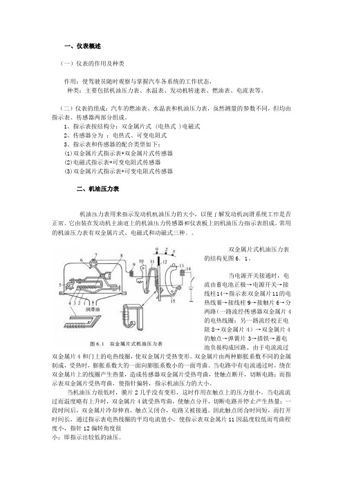
((指示 正常的机双金制成双金示表 过而段时时间度小小;一、仪表概(一)仪表的作用:使驾种类:主要(二)仪表的示表、传感器1、指示表按2、传感器分3、指示表和(1)双金属片(2)电磁式指(3)双金属片 二、机机油压常。
它由装在机油压力表有金属片4和门成,受热时,金属片上的线表双金属片受 当机油压力而温度略有上时间后,双金间长,通过指小,指针12偏即指示出较概述的作用及种类驾驶员随时观要包括机油压组成:汽车的器两部分组成按结构分:双分为 :电热和传感器的配片式指示表+指示表+可变片式指示表+机油压力表压力表用来指发动机主油道有双金属片式门上的电热线膨胀系数大的线圈产生热量受热弯曲,使力很低时,膜上升时,双金金属片冷却伸指示表电热线偏转角度很较低的油压。
类观察与掌握汽压力表、水温的燃油表、水成。
双金属片式 热式、可变电配合类型如下+双金属片式传变电阻式传感器+可变电阻式传指示发动机机道上的机油压式、电磁式和动线圈,使双金属的一面向膨胀量,造成传感器使指针偏转,膜片2几乎没属片4就受热直,触点又闭线圈的平均电流车各系统的工温表、发动机水温表和机油(电热式 )电阻式下:传感器 器 传感器 机油压力的大压力传感器和动磁式三种属片受热变形胀系数小的一器双金属片受指示机油压力没有变形,这热弯曲,使触闭合,电路又流值小,使指工作状态,机转速表、燃油压力表,虽电磁式大小,以便了和仪表板上的。
的结构流由蓄线柱热线两路的电热阻8→的触点池负极形。
双金属片一面弯曲。
当受热弯曲,使力的大小。
这时作用在触触点分开,切又被接通。
因指示表双金属燃油表、电流虽然测量的参了解发动机润的机油压力指 双金属片构见图6.1 当电源开蓄电池正极→14→指示表双圈→接线柱9(一路流经传热线圈;另一→双金属片4点→弹簧片极构成回路。
片由两种膨胀当电路中有电使触点断开,触点上的压力切断电路并停因此触点闭合属片11因温流表等。
参数不同,但润滑系统工作指示表组成。
汽车仪表与其它辅助电器的构造与识别一、汽车仪表汽车仪表是反映汽车安全行驶和技术经济性能的指示电气装置。
它通常包括:电流表、油量表、温度表、机油压力表及车速里程表等。
在气压制动的汽车上还有空气压力表,在某些柴油汽车上有转速表等。
图4-57东风EQ2102型越野汽车驾驭室电气仪表及辅助电器示意图。
图4-57 东风EQ2102型越野汽车驾驭室电气仪表及辅助电器示意图1-熔断器盒总成 2-熔断器片10A 3-熔断器盒盖 4-鼓风装置总成 5-制动灯开关6-离合器开关7-组合开关 8-组合开关罩盖9-点火锁总成 10-电器安装板 11-工作灯插座引线总成 12-工作灯插座 13-气压报警蜂呜器 16-括水间歇继电器 17-水温过热及水位过低蜂呜器 18-预热控制器 19-闪光器 20-报警闪光器 23、24-继电器 25-石英钟 26-空气压力表 27-空气管 30-压力表 32-暖风开关 33-面板总成 34-旋钮 35-主副油箱转换开关 36-停车及报警开关 37-气喇叭转换开关 38-雾灯开关 39-仪表板总成 40-里程表用软轴总成 41-预热开关 42-驾驶室电线束总成 43-干燥器开关 44-远距离控制开关 45-电源开关总成47-防空灯开关电气式仪表一般由指示器和传感器二部分组成,两者由电线连接,便于拆装维修更换和遥控,应用广泛。
组合式汽车仪表,是现代汽车仪表普遍采用的布置形式。
组合仪表有两种结构,一种是将全部仪表及指示灯组装在一个表壳内,共用一个玻璃面罩。
这种形式的组合仪表多用于轻微型车及轿车上,另一种是将几个较小的表,如水温表、燃油表、机油压力表等组装在一起,而将较大的表,如车速表、车速表等单独安装,这种形式多用于中型以上车辆上。
(一)电流表1.功用与型式电流表串连在蓄电池和发电机之间的电源电路中,用来指示蓄电池的充放电状况和发电机的工作情况。
如由蓄电池供电时,其指示值为负(-),发电机向蓄电池充电时示值为正(+)。
The basics of automotive cluster device architectures and applications, part IDeepak MahajanVIKAS AGARWAL,Arjun Pal Chowdhury, - December 01, 2014With the increased complexity of vehicle electronics, greater functionality requires status information to be displayed to the driver. The instrument cluster is the primary data source for the driver, delivering information about vehicle and engine status. Given system complexity, however, there is greater demand for a more user friendly, lucrative and cost-effective solution to support a wide range of automotive cluster applications. Here we will discuss various components of a cluster device that enable this support. The article classifies cluster architecture and applications into the following broad categories:Types of cluster devicesqAutosar application componentqGraphics application componentqCluster securityqDevice memory requirementqLow power mode cluster architectureqCluster Device TypesThere are three basic cluster device platforms, including:Cluster Graphics PlatformCar manufacturers and tier-1 suppliers are facing an increasing need for content to be displayed to the driver requiring instrument cluster solutions that can be dynamically reconfigured to display content based on context and driver preferences while presenting required information to ensure safe driving. Cluster graphics Platform is mainly used to fulfill the requirement. This device mainly consists of Graphics processor with 2D/3D accelerator, huge on-chip graphics RAM for high bandwidth graphics data access, high-speed external memory interface like SDR,DDR or Nand Flash Controller, display controller to display graphics information through TFT,LCD display. In addition, the set of integrated peripherals such as CAN, MOST MLB, LVDS, Ethernet and USB allow a direct connection to the rest of the car network. The device is generally used for high end cluster application by OEMs.Cluster Controller PlatformThis is the cluster MCU device that mainly handles the Cluster AUTOSAR stacks functionality. This device contains a stepper motor controller and driver for gauge driving, sound generation module, PWM channels for sound and cluster LED control, various analog sensors and communicationperipherals, HMI to communicate with driver, other body devices and gateway devices or other subsystem. The device can also have segmented LCD or even dot matrix LCD displays as an alternative display solution for low end cluster application. For high/mid range applications, most of the real time data and status captured by the device is communicated to cluster graphics device through fast SPI or EBI interface.Combined Cluster PlatformThe graphics controller and real time application controller (Cluster MCU) is combined in this platform to make single chip solution for both Graphics and Autosar application. This device keeps a balance between graphics performance and real time performance hence used by OEMs when optimum solutions are required. Some renowned semiconductor companies offer wide range of combined cluster platform microcontrollers with multi core based solutions to support from basic to premium line instrument cluster applications.Module Use-Case1. AUTOSAR Application ComponentsCore: The core is part of real-time application domain of the device. It is mainly used to run AUTOSAR applications such as basic a communication driver, PWM driver, handling and servicing of various peripherals etc. The high bandwidth motor control application driver can also be controlled through this core. The device can also have a dedicated core for motor control applications, which helps to share the bandwidth of the real time processor.Stepper Motor Control/Driver:In cluster application a stepper motor driver is mainly used to control gauges. Real-time information of vehicle speed, fuel level, tachometer, temperature etc., is communicated to cluster devices through a gateway device. The core then processes that information and updates the motor control driver to control the stepper motor. Two motor controlchannels are mainly used to drive a single stepper motor.PWM: PWM outputs are used to control the backlighting of LCD displays, gauge backlighting etc. The LED intensity of dashboard, odometer, etc., are controlled by PWM output. For low-end applications where few LED tell‐tales are required, it is controlled by microcontroller PWM output. However in mid-range or high-range applications where more LEDs need to drive the system, there is typically a dedicated LED driver.ADC and Alarm Comparator: These analog components are mainly used to monitor the current, voltages of various power supplies. They are also used to measure the current flow through Telltale LEDs to check that everything is working fine. Measuring the battery level, ignition level, air temperature and coolant are common ADC functions performed by either a cluster or body device. When performed by a body device, it is communicated to a cluster by using a LIN or CAN connector. Sound Generation Module: The device can have sound generation module with I2S protocol support, mainly to produce a buzzer sound in a cluster to indicate the occurrence of some unwanted event. For example, a driver seat belt warning detected by a body-device sensor is communicated to a cluster. The sound generation module inside the cluster device will create a buzzing sound to alert the driver of the event. Similarly door lock/unlock and other common events can be communicated through a sound generation module. It can also be used to play MP3 audio data with the help of a CPU that converts MP3 into PCM data for the I2S interface. CompnentsThe Communication InterfaceCAN Bus is the most common high speed communication network in Automotive ECU toqcommunicate with body and gateway devices that are sitting far from a cluster/dashboard.LIN provides cost‐efficient communication in applications where the bandwidth and the versatility qof CAN are not required. Communication with various sensors, actuators or body controllers is done via the LIN network. LIN is used to communicate to comparatively local devices such as communication between the steering wheel audio/music system control device with the cluster, headlight ON indication from sa witch to the cluster device, a side/parking indicator communication (side indicator/parking light switch to dashboard display and sound device) is handled by LIN. However these things are flexible and depend on end-user preference.SPI & IIC are mainly used for inter chip communication in short distances. SPI interface can beqused to access slow serial flash, to communicate with power control device sitting near to the cluster, LED drivers etc.Graphics Application ComponentThe use of LCDs started as a small “add-on-display” along with the electromechanical needles-based gauges to display additional information, but is now a trend in automotive instrument clusters as graphical displays replace traditional mechanical gauges altogether. The challenge is now how to give the user the same feel and realistic experience of the needles and pointers using graphics computation techniques. In addition, information that gets onto displays such as a seat belt indicator, tire pressure level, engine temperature, rear camera view, etc., is treated as safety relevant and considered safety critical. Other miscellaneous information such as navigation, song select, etc. are also part of these displays. The full color TFT LCD panels now allow automotive OEMs to provide state of the art interfaces with the following features:Menu-driven configurabilityqAnimated pointers on gaugesqText and graphics to a similar standard as desktop or handheld devicesqAll of the above features require a minimum desired display size support, specific frame-rate requirements and the capability of handling complex animations. The following components play an important role in achieving the required functionality:Application ProcessorThe applications processor is a high-performance core primarily used for managing the graphicsapplication in high-end cluster solutions. It is used to run the graphics drivers and generate commands for execution by the GPU. It is in general, a pipelined processor having precision Floating Point Unit (FPU) and Instruction/Data Caches for trapless and faster operations. It can also be equipped with an additional Media Processing Engine (MPE) extending the capabilities of the FPU for further acceleration of media and signal processing functions by adding instructions targeted at audio, video, 3-D graphics, image, and speech processing.In the graphics subsystem, the application running will call different APIs to access the graphics hardware through programming calls to the operating system. When the application requests an image to be rendered on the display, the API calls the OS, which in turn invokes the GPU driver to communicate with GPU hardware to draw the image to be shown on the display. From the perspective of the application processor, it accumulates and sets up graphics commands that are dispatched to the GPU for processing and display rendering. It does this by means of writing the commands to volatile memory (typically DRAM) where the GPU can subsequently fetch the commands. For example in‐case of digital display of needles (let’s say speedometer, fuel indicator, etc.), it will get the information from a real-time processor regarding the corresponding activity and instruct the GPU to rotate the needle at a certain angle. It will control all of the APIs for creating the needle rotation graphics. It instructs the GPU to rotate image, coloring the image, zooming the image, etc.The MPE associated with it can also be used as JPEG decoder (or limited MPEG decoder) to display images through the display controller. For example, in an advanced speech and navigation system, the navigation unit can send images/frames through Ethernet to display to a cluster RGB display unit. Those JPEG images need to be decompressed and decoded by the MPE and then displayed through a display controller onto an LCD/TFT display. Similarly for audio applications, MP3 data can be sent through Ethernet to cluster devices and software can convert the MP3 format to a PCM format with the help of MPE to play it through speakers using I2S protocol to support in-car entertainment.Graphics Processing UnitA graphics-processing unit (GPU) is a specialized module designed to rapidly manipulate and alter memory to accelerate the creation of images in a frame buffer intended for output to a display via a display controller. GPUs are very efficient at manipulating computer graphics and their highly parallel structure makes them more effective than general-purpose CPUs for algorithms where processing of large blocks of data is done in parallel. They have much deeper pipelines compared to traditional CPUs along with significantly faster and more advanced memory interfaces to shift around a lot more data than CPUs. It helps in offloading the main core by handling geometry and pixel processing, allowing resolution independent HMI.In mid-end cluster solutions, the high performance GPU can be a 2D vector and raster graphics accelerator designed for hardware acceleration of vector graphics, which can be displayed using a display controller. The GPU can be accessed through its specific drivers. It can also provide scalability with high-quality rendering, including anti-aliasing, to different screen sizes without multiple bitmaps.A GPU supports graphics application programming interfaces (APIs) that provide user controls for optimizing the acceleration capabilities available with the GPU. It is preferable to support a hardware platform and operating system (OS) independent software APIs standard rather than aproprietary API standard for enhanced vector graphics. One such standard is OpenVG 1.1 API standard for vector graphics acceleration. OpenVG is a royalty-free, cross-platform API managed by a member-funded consortium. It provides a low-level hardware acceleration interface for vector graphics libraries such as Flash and Scalable Vector Graphics (SVG). It is used for acceleration of high-quality vector graphics for user interfaces and text on small screen devices. ControllersCore API features of OpenVG include Coordinate systems and transformations (image drawing uses a 3x3 perspective transformation matrix); Viewport clipping, scissoring and alpha masking; Paths; Images; Image filters; Paint (gradient and pattern); Blending; Dithering. The VGU Utility Library provides Higher-level geometric primitives, Image warping.Typical use cases in the instrument cluster are where a GPU will accelerate the needle rotation and display controller renders the rest of the scene, for infotainment where it can be used for User Interface (UI) acceleration, for native rendering of true-type fonts with Anti-Aliasing, additional graphics acceleration for dual display systems, etc.Display ControllerThis is the main graphics display controller of the device. It is designed to drive displays using direct blit graphics and video with RGB data. It generates all of the necessary signals required to drive the displays with up to 24-bit RGB data bus, Pixel Clock, Data Enable, Horizontal-Sync, and Vertical-Sync. There can be as many as two independent controllers in a high-end cluster solution for driving two different displays simultaneously. two is not the limit.The specified internal memory of the device allows the controller to easily handle complex graphics contents (pictures, icons, languages, fonts) with a very low memory footprint. It can also be used for creating simple animation without any help of dedicated graphics processor, for e.g., image sequence animation (to display a rotating car), list scroll, object fade in/out, fly in/out, dynamic reveal/hide, etc.Graphics are managed through planes blending using the merging of multiple programmable layers (objects) to optimize use of internal memory buffers. Since the CPU need only to manage the configuration of the layers, it is possible to create animations with low CPU overhead and minimal RAM footprint.There can be a number of extensions to the display controller interfaces and capabilities to support wide range of flat panel or curvature displays available in market based on product requirement. A few of them include:RSDSIt can also interface with on-chip TCON (Timing Controller) to generate the timing signals and to directly drive the row and column drivers of display panels via RSDS (Reduced Swing Differential Signaling) pads. RSDS is having a voltage swing of 200mv and is similar to the Low Voltage Differential Signal (LVDS). RSDS interface signals instead of TTL based signals leads to the reduction of EMI in between the Panel Timing Controller and the Column drivers. The reduced signal swing level of RSDS also results in low power consumption and EMI levels as compared to TTL based interface.LVDSIt can also support the Open LVDS(Low Voltage Differential Signaling) Display Interface (OpenLDI) specification through an on-chip converter which converts the digital RGB into OpenLDI-compatible format of 4-data-pair and 1 clock pair LVDS interface output. It minimizes the number of wires that must be used to connect the display source and display device while also minimizing radiated emissions and susceptibility to electromagnetic interference. This enables the display controller to support a wide range of display formats, refresh rates, and pixel depths.HUDOne of the recent and latest features that have come up is of the head-up display (HUD). A head-up display is a display technology projecting the content directly on the windscreen of the car. As the windscreen is not a flat projection area, the image gets distorted. So to compensate this effect, in-line, real-time warping is being performed on the content to be displayed using the graphic accelerator or dedicated hardware. The fundamental advantage of such display is that the information is presented in the normal field of view of the driver looking onto the street. It will enhance safety while delivering navigational and other critical information to drivers such as speed, fuel level, etc. Head-up displays are usually used in combination with a TFT display in the instrument cluster.Video Input UnitThe Digital Video Input module is mainly used to take a compatible video stream or other supported formats as input from an external interface like reverse camera, driver monitor camera, etc. and then enabling a set of processing on the captured digital video to finally get it displayed through the Display Controller to TFT/LCD Display for the user/driver. Different kinds of processing on video include brightness adjustment, contrast adjustment, up-scaling or down-scaling of the picture, input data format conversion from one color space to other, horizontal mirroring for reverse camera adjustment, etc.In case of analog camera input, the picture information is transmitted to some off‐chip Video ADC which converts the signal to Digital and feed to this module. Usually RCA composite cables are used to connect the analog camera to the converter. ConclusionRLE DecoderThis module is used to decode data that has been compressed using a Run Length Encoding (RLE) scheme. Run length encoding is a simple scheme that compresses data based on repetition of consecutive entries. Each block of data is preceded by a command byte that indicates whether compression is active and if so how many copies of the next data are required.The RLE decoder performs extraction of run length encoded data and is optimized forextraction/decompression of graphic images and put it back in local memory for Display Controller to display. Data are fed to RLE typically using DMA and decompressed data are fetched typically by DMA. Any portion of a graphic can be decoded based on given start-pixel location and given end-pixel location. Apart from lossless decompression, it also supports the partial image decoding feature.Segmented LCD ControllerThis controller is equipped with multiple Front and Back plane drivers with the backplane drivers remapping feature to drive the external segmented LCD to display clock, odometer, trip meter, etc. or other related information. It is configurable to support multiple varieties of segmented displays. This module is also responsible for On-chip generation of all output voltage levels that are required to drive the display segments. It also supports programmable frame clock generator, programmable bias voltage level selector, programmable output current and an optional output current boost during transitions for displays along with the contrast adjustment feature. In a low cost solution, segmented LCD display can be an alternate option to graphical TFT display.ConclusionIn our modern age with a highly featured digital solution, all existing luxury is transforming into necessity and creating scope for new innovation. Hence the immediate challenge is to provide integrated solutions that are cost effective and technically advanced to fulfill market requirements. The automotive cluster has transformed from analog gauges to digital displays to integrated cluster infotainment solutions. The future trend will be to move towards a highly integrated solution where basic cluster, infotainment, advanced driver assistance will all be integrated in a single device. Hence it is very important to understand the basic architecture to know how they can be used to create an integrated cost-effective solution for the future.Read Part II, which covers cluster security requirements and application, device memory requirements, and low power mode cluster architecture.ReferencesPremium Line Instrument Cluster1.2.Designing a Vehicle Instrument Panel Cluster—A Case Study3.FPD-LinkLow-voltage differential signaling4.5.SuperImaging HUD。