KZT系列单输入通道数字式智能仪表说明书
- 格式:pdf
- 大小:1.58 MB
- 文档页数:36

K系列可编程数显仪表使用说明书一、概述K系列可编程智能报警变送仪表是在x系列数显电测表基础上增加以下功能和特点:1、显示倍率、通讯地址、波特率等通过面板上按钮可任意设置,使用非常灵活方便。
2、可选择被测量值的变送输出,输出为4--20mA,0—5V,4—12—20mA等可选。
3、带RS-485数字接口,采用标准MODBUS-RTU协议,具备字通讯和字节通讯方式,自带上位机测试软件。
4、使用范围广、组合功能强。
5、具有上下限报警功能,上下限报警允许设定功能,用户可以灵活组合使用以实现某些控制功能。
6、数字校零、数字校调,精度高,性价比极高。
二、通用技术指标精度等级:显示精度:0.5% 0.2%显示:四位LED 另加符号位量程:AC1A、AC5A、DC20mA,AC100V、AC220V 、AC380V、DC75mV等,特殊量程可定做工作频率:50/60HZ工作电源:AC220V、DC220V、AC110V、DC110V(由客户指定)功耗:小于3V A平均无故障工作时间:大于50000H工作条件:环境温度:-10至55℃相对温度小于93% 海拔小于2500米报警输出口:端子COM-NC为常闭触点端子COM-NO 常开触点通讯接口:端子GND为485地线,端子A为485+ 端子B为485-三、外形及接线图(具体以实物为准)四、编程说明仪表共设四个按键,分别为“←”“→”“MENU”“”“←”键:左移键菜单进行左移动选择,或是对所设定数字进行减功能,设定大数据时持续按该键可实现快速减功能。
“→”键:右移键,对菜单进行右移动选择,是对所设定数字进行加功能,在设定大数据时持续按该键可实现快速加功能。
“MENU”键:编程键,用此键可进入编程菜单,或是跳回上一级菜单,忽略操作。
“”键:确认键,用于进入下一层菜单或操作确认。
仪表参数设定说明:该仪表采用四键制设定输入,用“MENU”键进入编程菜单前,须输入编程密码“0001”,仪表共有13项设定功能。


GCS型光栅数显系统(英文米字管提示)使用说明书恒兴星精密仪器有限公司尊敬的用户:欢迎您使用深圳市恒兴星最新开发液晶英文提示的GCS 光栅数显系统,恒兴星光栅系统广泛用于铣床、磨床、镗床、线切割、车床,它的应用有助于提高生产效率、显示直观、操作方便、精度准确、重复性稳定,是模具制造业、机械加工业、精密测量仪器必不可少的装置。
本系统设置多种智能化功能,如SDM300点记忆、等分圆和椭圆、斜面加工、R的加工8 个面选择、分中功能的用法,还配置了计算器,等等功能,使用起来十分方便。
应用恒兴星的光栅数显系统,不须经过培训,按照英文使用说明书每步提示一看就懂。
最适合刚使用操作的新手,对于熟练得操作者更是得心应手。
要想了解有关的细节请详细阅读使用说明书。
安全注意事项:打开产品包装,取出箱内数显表与电子尺相接,然后插上电源检查显示是否正常。
①开箱后检查外观是否完好,若有故障应立即联系本公司销售部,切勿自行拆卸维修。
②本装置使用110V~220V,50Hz~60Hz的交流电源,电源插头是带有接地脚的三芯电源插头。
三芯电源插座地线一定要接地牢靠。
③用户不可以自行打开机壳修理,表内有很高压电源以免造成人员伤害。
④本机壳是采用ABS工程塑料,不具防爆高温的环境中使用。
⑤平时不用时请关闭电源,可延长本产品使用时间。
⑥在雷雨天气时应关闭或拔掉电源线以免高压雷击电网引起表的电源电压突然猛增高而烧毁表内电源,给用户带来不必要的损失。
日常维护:①每天下班时,清洁时请关闭电源。
②用干布或毛刷擦拭数显表或电子尺防护外壳。
③不能用甲苯或乙醇清洗外壳。
④数显表外壳或显示窗的污迹可用洗衣粉和水搅匀用毛巾扭干水擦拭。
承诺:本公司产品如因用户使用操作不当造成电子尺和数显表的损坏,特别是因碰撞造成产品外观或内部损坏,或自行拆下电子尺限位,造成因超行程把尺撞坏,需本公司维修服务的,本公司要收取适当的材料费和维修费。
面板按键说明GCS-900目录功能项目 (7)清零 (8)输入坐标 (8)公/英制显示 (8)ABS/INC坐标 (9)自动分中 (10)RI(寻找师傅零位) (11)半径/直径 (11)计算器 (11)SDM300组记忆 (12)圆周分孔 (18)椭圆分孔 (21)斜线分孔 (25)圆弧加工 (27)平滑圆弧加工 (35)斜面加工 (39)基本参数 (42)高级用户 (43)光栅线位移传感器 (45)光栅线位移动传感器行程和安装尺寸 (48)安装示图 (49)故障分析与处理 (50)GCS-英文提示光栅数显表,英文辅助显示智能表,采用高科技软件电子技术,功能多、易操作、可靠耐用,使机械加工的必备产品。

YW-KZT开关状态综合指示仪使用说明书保定钰维电气科技有限公司YW-KZT开关状态综合指示仪开关状态显示·手车柜的手车试验、工作位置状态显示·固定柜的上隔离分合,下隔离分合状态显示·断路器状态显示·电机储能状态显示·接地刀状态显示·其他特殊要求开关状态显示高压带电显示及闭锁·母线带电时,启动高压带电显示·达到闭锁电压时实现电磁锁闭锁温湿度控制·最多支持两路环境温湿度测量·温湿度控制功能最多支持两路加热器输出·可设置加热器启动条件,包括湿度上限和温度下限通讯功能·接口类型RS-485·通信规约MDBUS规约RTU模式目录一、用途 (3)二、概述 (3)三、技术指标 (4)四、工作原理 (5)五、使用方法 (5)六、模拟显示指示图 (6)七、安装方式及接线 (7)八、传感器安装 (8)九、注意事项 (9)十、原理接线图 (9)YW-KZT开关状态综合指示仪一、概述YW-KZT开关状态综合指示仪是一种多功能、全数字、智能化的高、低压开关柜显示与控制装置,适用于中置柜、手车柜、固定柜、环网柜等多种开关柜,集多种功能于一体,完全取代传统的一次回路模拟指示牌、电磁式开关状态显示器、接地指示器及除湿加热控制器等诸多元件,简化和美化了面板结构,方便了组装和接线,能迅速、直观地反映柜体运行状态,并能够通过RS-485总线与后台监控计算机组网通信。
选用时您只需提供一次系统图即可。
二、特点1.高可靠性:采用光电和电磁隔离技术,配以工业级元件和专业的抗干扰设计,同时进行全面的三防处理,使产品具有优异电磁兼容性能,并能耐受盐雾、酸雾、霉菌、导电尘埃等的侵蚀;2.功能完备:集成一次回路模拟图、隔离开关状态、弹簧储能状态、断路器位置、接地刀状态、高压带电指示、高压带电闭锁、温湿度显示与控制、通讯等多种功能;3.全数字化:采用微控制器技术对开关柜中各元件的工作状态实时采集,自动进行除湿加热控制与加热回路故障诊断,并将全部信息上传至上层,,便于实现对于采用多台开关柜组成的电气一次系统的实时动态运行模拟与远程环境监控;4.快速直观:面板配有符号管,数码管和LED,实时指示开关器件状态,柜内温湿度值和运行状况;5.无源带电指示:面板配有超高亮带电指示LED,可通过带电传感器由主回路高压直接点亮,装置无需上电即可提醒主回路带电;三、技术指标1、工作电源:交流或直流100V~265V.2、使用环境:温度-25℃~85℃相对湿度<95%RH3、整机功耗:<5W4、抗电强度:AC2500V 50Hz历时1分钟5、绝缘性能:大于100MΩ6、开关状态显示说明6.1、断路器状态指示(无源触点输入)断路器默认为分闸状态,绿色模拟条亮,“断路器”端子取合闸信号,合闸时红色模拟条亮。
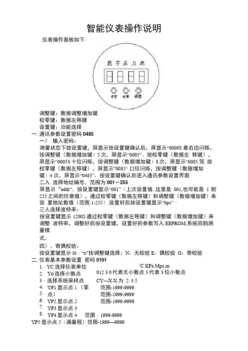
智能仪表操作说明仪表操作面板如下:调整键:数据调整增加键校零键:数据左移键设置键:功能选择一.通讯参数设置密码0485一).输入密码:测量状态下按设置键,屏显示按设置键确认后,屏显示“0000S 最右边闪烁,按调整键(数据增加键)5次,屏显示“0005”,按校零键(数据左 移键),屏显示“0005S 十位闪烁,按调整键(数据增加键)8次,屏显示“0085笃 按校零键(数据左移键),屏显示"0085^ 口位闪烁,按调整键(数据增加键)4 次,屏显示“0485”,按设置键确认后进入通讯参数设置界面 二入 选择地址编号,范围为001〜255屏显示“addr”,按设置键显示“001”(上次设置值,这里是001,也可能是 1 到255之间的任意值),通过校零键(数据左移键)和调整键(数据增加键)来设 置地址数值(范围1-255),设置好后按设置键显示“bps”・ 三人选择波特率:按设置键显示1200S 通过校零键(数据左移键)和调整键(数据增加键)来调整 波特率,调整好后按设置键,设置好的参数写入EEPROM,系统回到测量模式。
四)、奇偶校验:按设置键显示bl ・“x”按调整键选择:N :无校验E :偶校验 O :奇校验二.仪表基本参数设置 密码0101'C KPa Mpa m 012 3 0代表无小数点3代表3位小数点 CY —X X 为 2. 3.5 YP1显示点1 (零点) YP2显示点2 YP3显示点3 YP4显示点4 范圉・1999-9999YP5显示点5(满量程)范围-1999—99991. YC 选择仪表单位2. Yd 选择小数点3・选择系统采样点4. 5. 6. 7. 8. 范围-1999-9999范围-1999-9999范围-1999-9999注:5个显示点的设置必须等间隔如:传感器为压力传感器0…50MPa,YC选MPa, Yd选2, YP1选00.00.YP2 选 12.50.YP3 选 25.00.YP4 选 37.50.YP5 选 50.00。

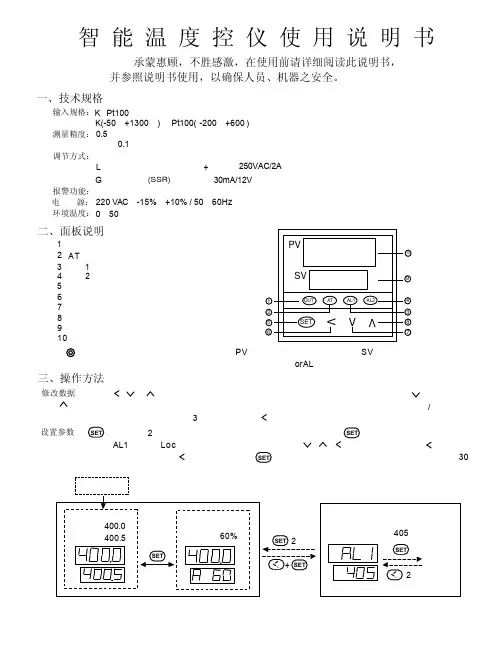
三、操作方法OUTATAL1AL2SETVVVPVSV13245867910修改数据:可通过按、或键来修改。
给定值。
仪表同时具备数据快速增减法和小数点移位法按键减小数据,按键增加数据,可修改数值位的小数点同时闪动(如同光标)。
按键并保持不放,可以快速地增加/减少数值,并且速度会随小数点会右移自动加快(3级 速度)。
而按键则可直接移动修改数据的位置(光标),操作快捷。
设置参数:2秒钟,即进入参数设置状态。
在参数设置状态下按键,仪表将依次显示各参数,例如上限报警值AL1、参数锁Loc 等等,如果参数没有锁上可用、、等键修改参数值。
按键并保持不放,可返回显示上一参数。
先按键不放接着再按键可退出设置参数状态。
如果没有按键操作,约30秒钟后会自动退出设置参数状态。
仪表上电后,仪表上显示窗口显示测量值(PV ),下显示窗口显示给定值(SV )。
输入的测量信号(输入断线或短路均可能引起)时,则闪动显示orAL ,此时仪表将自动停止控制。
调节输出指示灯(1)报警(3)指示灯1报警(4)指示灯2(2)指示灯(本型号未使用)AT 显示转换(兼参数设置进入)(5)数据移位键(6)数据减少键(7)数据增加键(8)给定值显示窗(9)测量值显示窗(10)二、面板说明输入规格:K 、Pt100测量范围:K(-50-+1300)、Pt100(-200-+600)测量精度:0.5级测量显示分辨率:0.1℃调节方式:位式调节或带自整定功能的智能调节输出规格:继电器触点开关输出(常开+常闭),250VAC/2A L 固态继电器G 电压输出,(SSR)30mA/12V (用于驱动固态继电器)报警功能:上限报警电 源:220VAC ,-15%,+10% / 50-60Hz 环境温度:0-50℃智 能 温 度 控 仪 使 用 说 明 书承蒙惠顾,不胜感激,在使用前请详细阅读此说明书,并参照说明书使用,以确保人员、机器之安全。
一、技术规格超出量程四、自整定(AT)操作本系列采用的智能调节算法是应用了模糊规则进行PID 调节的一种新型算法,具有自整定功能并在调节中记忆被控对象的部分特以使效果最优化,无需人为调节参数,使用简便。
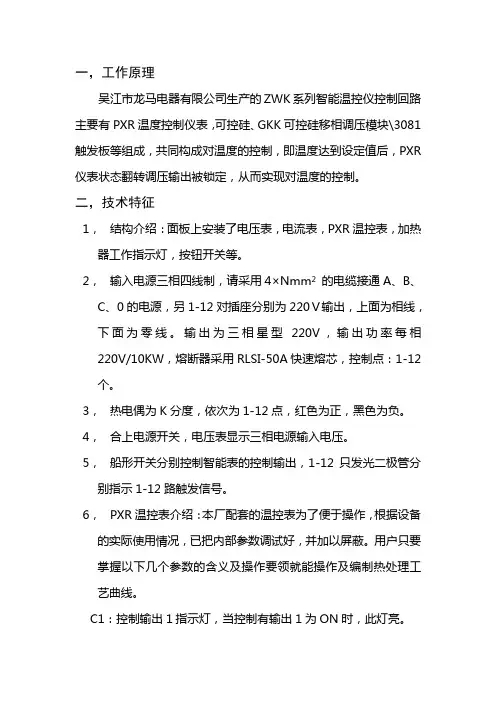
一,工作原理吴江市龙马电器有限公司生产的ZWK系列智能温控仪控制回路主要有PXR温度控制仪表,可控硅、GKK可控硅移相调压模块\3081触发板等组成,共同构成对温度的控制,即温度达到设定值后,PXR 仪表状态翻转调压输出被锁定,从而实现对温度的控制。
二,技术特征1,结构介绍:面板上安装了电压表,电流表,PXR温控表,加热器工作指示灯,按钮开关等。
2,输入电源三相四线制,请采用4×Nmm2的电缆接通A、B、C、0的电源,另1-12对插座分别为220V输出,上面为相线,下面为零线。
输出为三相星型220V,输出功率每相220V/10KW,熔断器采用RLSI-50A快速熔芯,控制点:1-12个。
3,热电偶为K分度,依次为1-12点,红色为正,黑色为负。
4,合上电源开关,电压表显示三相电源输入电压。
5,船形开关分别控制智能表的控制输出,1-12只发光二极管分别指示1-12路触发信号。
6,PXR温控表介绍:本厂配套的温控表为了便于操作,根据设备的实际使用情况,已把内部参数调试好,并加以屏蔽。
用户只要掌握以下几个参数的含义及操作要领就能操作及编制热处理工艺曲线。
C1:控制输出1指示灯,当控制有输出1为ON时,此灯亮。
C2:此功能不用。
AL1,AL2,AL3:为报警功能灯,此功能不用。
PV:测量值显示(红),另在设定参数时,指示参数名称。
SV:设定值显示(绿),另在设定参数时,指示上面参数的数值。
靠SEL键切换。
∧∨:增/减键,用于改变SV值(仅在定点自由升温rOFF时),顺序选择参数及增/减参数值。
SV指示灯:显示设定值(SV)时此灯亮。
三,仪表设置各部分的含义:C1:控制输出1指示灯,当控制输出1为ON时,此灯亮。
C2:本厂仪表无此功能H.L.HB报警灯本厂仪表无此功能。
PV测量值显示。
SV设定值显示,指示设定值另外在设定参数时,指示参数数据。
SEL键(参数选择键)用于选择参数组,选择参数组和参数值显示等。
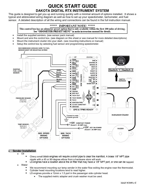
QUICK START GUIDEDAKOTA DIGITAL RTX INSTRUMENT SYSTEMThis guide is designed to get you up and running quickly with a minimal amount of options installed. It shows a typical and abbreviated wiring diagram as well as how to set up your speedometer, tachometer, and fuel sensor. A detailed description of all the wiring and connections can be found in the full instruction manual. •Install the supplied senders. (see sensor pack manual) •Mount and wire the control box. (see diagram on this sheet or see manual for more detailed descriptions) •Mount the instrument cluster into your dash. (see mounting instructions or manual) • Setup the control box by selecting fuel sensor and programming speedometer.• Sender Installationo Oil▪ Chevy sma ll block engines will require a short pipe to clear the manifold. A brass 1/8” NPT pipenipple with a 45 or 90-degree elbow from a hardware store will work. ▪ LS engines have a location above the oil filter that may have a 1/8” NPT port, or one can be tapped.o Water▪ We recommend mounting our temp sender in the water flow exiting the engine near the thermostat. ▪ Cylinder head mounting locations tend to read higher. ▪ LS engines provide a 12mm x 1.5 port in the passenger side cylinder head.• The supplied metric adapter and crush washer must be used.***** IMPORTANT NOTE! *****This control box has an odometer preset option that is only available within the first 100 miles of driving.See “ODOMETER PRESET MENU” in main instruction manual for details.Instrument Cluster•SPEED SENSOR WIRING OPTIONS•TACH WIRING OPTIONS•Diesel engines will require the SGI-100BT to obtain a valid tachometer signal•Control Box MountingInstrument Cluster o The control box must be mounted inside the cabin of the vehicleo Do not mount a coil or MSD ignition box inside the vehicle with the controlbox▪The high voltage output of either device will interfere withelectronicso Do not mount the control box direct across from distributor on inside firewall▪ A high voltage points or HEI distributor can interfere with electronicso Do not mount the box near the A/C ducts, to prevent condensation fromharming the electronicso Do not run straight wire leads / harnesses to the control box▪ A loop or bend in the wiring can help prevent any moisture damage• A leaky window or condensation can let moisture run intothe box without a drip loop•Set up the control box to match your vehicleo The switch assembly MUST be installed and be within reach of the driver▪The switch allows the driver to change message displays while driving▪The switch is required to enter setup, set clock, reset trip meter and more▪No switch installed will generate a CONNECT SWITCH error messageo Calibrate speedometer, for accurate speed regardless of gearing and tire sizeo Adjust the tachometer to match the engine’s number of cylinders.o The fuel gauge must be set to match the sender in your tank. We provide 10 common sender options; if yours is not listed, the system can be programmed to a custom sendero A battery disconnect will not cause loss of settings, only the time for the clock.•Speedometer Calibrationo The setup procedure described below is AUTO CAL using any of the pictured VSS wiring optionso You must have a known one mile (or one kilometer) run mapped out prior to starting▪To enter speed setup: hold Switch 2 (II)▪START the car – > Release when engine is running and display says SETUP▪Tap Switch 2 (II) to highlight SPEED▪Hold Switch 2 (II) to enter speed setup – > Release when prompted▪Hold Switch 2 (II) as AUTO CAL is highlighted – > Release when prompted▪Display will show DRIVE 1 MI (KM) with a 0 below▪Start driving the distance, the 0 will begin to count up the speed pulses▪When you reach the end of the mile (kilometer) run, – > Tap or hold either switch to save▪The menu will display BACK and in an upper screen it will show the number of pulses▪Hold either switch to exit the speed menu – > Release when prompted▪Tap Switch 1 (I) until you have EXIT SETUP highlighted▪Hold either switch to exit – > Release when prompted•Tachometer Calibrationo Old school V-8 points or HEI systems: with or without a MSD box, will not need any setupo Six and four cylinder engines need the cylinder count changedo LS engines: signal from the ECM will read as a four cylinder, and it will be a low voltage input▪To enter tach setup: hold Switch 2 (II)▪Turn ignition on – > Release switch when display shows SETUP▪Tap Switch 2 (II) to highlight TACH▪Hold Switch 2 (II) to enter tach setup – > Release when prompted▪The display will show INPUT▪Hold Switch 2 (II) to enter Input setup – >Release when prompted▪The display will show CYLINDER▪Hold Switch 2 (II) for Cylinder setup – > Release when prompted▪The display will show the cylinder count with *8 as the current default setting▪Tap the left button until 4 is displayed▪Hold Switch 2 (II) to save – > Release when prompted▪The display will show CYLINDER▪Tap the right switch to change display to TYPE▪Hold Switch 2 (II) to enter Type setup – > Release when prompted▪The display will show *12V HIGH as the default tach voltage▪Tap Switch 2 (II) to highlight 5V LOW▪Hold switch to save – > Release when prompted▪You may stop by turning the key off or go “Back” in each menu and “Exit Setup”•Fuel Setupo To enter fuel setup: hold Switch 2 (II)o Turn ignition on – > Release switch when display shows SETUPo Tap left Switch 2 (II) to highlight FUELo Hold Switch 2 (II) to enter fuel setup – > Release when promptedo The display will show INPUTo Hold Switch 2 (II) to enter fuel sender choices – > Release when promptedo Use the switches to scroll up or down to highlight your sender from the list below▪As each sender is highlighted, the fuel needle will respond to that choiceFuel Sender type Menu Empty R Full RChrysler – typically uses a 73-10 ohm FORD 73-10 73 ohms 10 ohmsGM 0-30 ohm (mid 60’s-earlier) GM 0-30 0 ohms 30 ohmsGM 0-90 ohm (mid 60’s-late 90’s)GM 0-90 0 ohms 90 ohmsGM 40-250 ohm (late 90’s-later) GM 40-250 40 ohms 249 ohmsGM 250-40 ohm GM 250-40 249 ohms 40 ohmsGM 90-0 ohm (63-67 Corvette) 63 VETTE 90 ohms 0 ohmsFORD 73-10 ohm (earlier -late 80’s)FORD 73-10 73 ohms 10 ohmsFORD 20-150 ohm (late 80’s-later) FORD 20-150 20 ohms 150 ohmsVDO 10-180 ohm VDO 10-180 10 ohms 180 ohmsSW/SUN 33-240 SW 240-33 240 ohms 33 ohmsASIA 112-4 ohm (various imports) ASIA 112-4 112 ohms 4 ohmsUser programmed MANUAL ADJ User settable User settable o Hold Switch 2 (II) to save, release when instructed on screeno Tap Switch 2 (II) to highlight BACK– > Hold switch to save – > Release when promptedo Tap Switch 1 (I) until you have EXIT MENU highlightedo Hold switch to save – > Release when promptedSee full installation manual for custom fuel sender calibration in the MANUAL ADJ mode •Clock Setup (not visible with all LCD layouts)o Small screens will not display a clock in the main speed screeno The clock must be added to a Group Screen▪Small screens will only have two locations to display, Screen 1 and Screen 2 o When the LCD is showing a clock, tap the Switch (I) to move a small arrow next to the clocko Hold Switch 1 (I) – > Release when prompted – > The hours will begin flashingo Tapping Switch 1 (I) will decrease hours, while the Switch 2 (II) will increase hourso When the correct hour is displayed – > Hold either switch to save – > Release when promptedo The minutes will be flashing – > Tap (I) to decrease minutes – > Tap (II) to increase minuteso Hold either switch to save – > Release when prompted•Dakota Digital Automotive Bluetooth Appo The free app for Apple and Android devices can be used to setup all the featureso The RTX system MUST be in Setup mode before changing settings▪Only Androids must pair to RTX before opening the appWARNING: This product can expose you to chemicals including lead, which is known to the State of California to cause cancer and birth defects or other reproductive harm. For moreinformation go to 。
高性能的数字显示报警仪使用说明z 主要技术指标:1、显示范围:-1999~9999,小数点位置可设置。
2、测量及变送输出准确度:±0.2%FS±1字;±0.1%FS±1字(需特殊订制。
3、输入信号:热电偶: K、E、S、B、J、T、R、N;冷端温度自动补偿范围 0~50℃,补偿准确度±1℃。
热电阻:Pt100、Cu100、Cu50、BA2、BA1;引线电阻补偿范围≤15Ω。
直流电压:0~20mV、0~75mV、0~200mV、0~5V、1~5V;0~10V(订货时需指定,与其他信号不兼容。
直流电流:0~10mA、4~20mA 。
线性电阻:0~400Ω(远传压力表。
频率:0.1Hz-10KHz。
(该功能需单独指定,与其它信号不兼容输入。
4、模拟输入阻抗:电流信号Ri=100Ω;电压信号Ri=500KΩ。
5、模拟输出负载能力:电流信号:4~20mA输出时Ro≤750Ω;0~10mA输出时Ro≤1.5KΩ。
电压信号:要求外接仪表的输入阻抗Ri≥250KΩ, 否则不保证连接外部仪表后的输出准确度及线性度。
6、配电输出:DC24±1V 30mA,过流自动保护。
7、报警方式:单回路可对应四个报警点,双回路仪表每回路对应 2个报警点。
8、通讯方式:RS232(10m或 RS485(1000m 9、使用环境:环境温度:-10~55℃,环境湿度:10~90%RH。
10、耐压强度: 输入/输出/电源/通讯≥1000V.AC 1分钟。
11、绝缘阻抗: 输入/输出/电源/通讯≥100MΩ。
12、电源:开关电源:交流:85~265V,频率: 50Hz±2Hz; (推荐使用线性电源:交流:220V±10V,频率: 50Hz±2Hz; (变压器电源,不推荐使用直流电源:DC 24V (适用范围 16V-28V13、功耗:<4W。
特点:⊙测量项目:三相电力网络电压/电流/有功功率/无功功率/频率/ 功率因数等,共28个电参数⊙2路开关量输入和2路开关量输出(可选四路开关量输入)⊙真有效值测量⊙具有RS485数字接口,采用Modbus RTU通信协议⊙具有一路有功电能脉冲输出⊙具有正向有功电度和反向有功电度记录功能,即可分别记录 消耗和发出的电能!KKES9LC01-A/1-20180822三相智能电量仪表操作说明书该系列仪表可广泛应用于控制系统、SCADA系统和能源管理系统中、变电站自动化、配电网自动化、小区电力监控、工业自动化、智能建筑、智能型配电盘、开关柜等各种自动化控制系统中,具有安装方便、接线简单、维护方便、工程量小、现场可编程设置输入参数等特点。
1、如果不按说明书操作会发生意外,而且会导致产品毁坏。
2、本说明书中所提供信息可不经事先通知进行修改。
3、本公司对所述信息保留解释权。
警告声明:一次侧电流设定(单位:A)二次侧电流设定(单位:A)仪表地址设定更改数据后按SET确认或按ESC回退至上一层五、菜单流程图清除电度用户密码设定一次侧电压设定(单位:kV)二次侧电压设定(单位:V)选择测量信号的输入网络测量状态背光时间翻页时间电能界面切换流程举例说明:总有功电度(代数和)正向有功电度反向有功电度总无功电度(代数和)第1页电源功耗显 示功 率频 率电流精度储存环境工作环境报警输出开关量输入电源工作范围电 能输出数字接口脉冲输出RMS测量 准确度等级0.5级有功、无功、视在功率,准确度等级0.5级45~60Hz、 精度0.01Hz有功电能1级、无功电能2级LCD大屏幕显示(可选蓝色背光,默认为白光)AC/DC 100~240V (85~265V)≤5VARS-485,采用MODBUS-RTU 协议1路电能脉冲输出(集电极开路的光耦输出) 脉冲常数3200imp/kWh 2路开关量输入(干结点方式)2路开关输出,250VAC/3A或30VDC/5A(可选,请咨询销售)温度:-10~50℃ 湿度:<85% RH ;无腐蚀气体;海拔高度≤2500m -40~70℃电流阻抗电流功耗电压功耗电压过负荷网络一、仪表型号二、型号说明三、主要技术参数电压测量范围<0.4VA (每相)<20mΩ电流过负荷电压阻抗电压精度电流测量范围≥300KΩRMS测量 准确度等级0.5级AC 0.025~5A持续:1.2倍 瞬时:10倍/10S 三相三线、三相四线AC 3×220V/380V(3x57.7V/100V)持续:1.2倍 瞬时:2倍/10S <1VA (每相)输入信号:报警输出:模拟输出:型号系列:显示方式:外形尺寸:E S 9 L □ □ □ □ □38:三相带通信C : 表示两路报警 A : 无报警30 : 三相不带通信量程代号:A5:AC 0~5A V450:AC 0~450V B:5A*450V A:5A*100V R : 无此功能空:无此功能信号输入:V:三相电压 A:三相电流 W:三相电压及电流L:段码液晶显示T:TFT彩屏液晶显示9:96H×96W×61.5L(mm)ES系列三相电量表通讯功能型号ES9L-A381路RS485ES9L-RC381路RS485ES9L-V-RC38V4501路RS485ES9L-A-RC38A51路RS485ES9L-W-RC38输入A:5A*100V B:5A*450V A5:AC 0~5A V450:AC 0~450V1路RS485四、面板说明测量界面切换流程说明:隔离耐压重量绝缘外形尺寸电源与485接口,DI接口,脉冲输出接口≥DC 2000V 输入、输出、电源对机壳>5MΩ96W×96H×61.5L(mm)0.5kg查看测量值及仪表工作状态说明:1.在测量状态下,按键“ / ”进行三相相电压、三相线电压、三相电流、三相有功功率、三相无功功率、三相功率因2.按键“ / ”增加减少键为总有功电度(代数和)、正向有功电度、反向有功电度、总无功电度(代数和)、正向无功电度、反向无功电度切换显示。
可编辑修改精选全文完整版科力达RTK 产品系列风云K9系列RTK测量系统产品手册科力达仪器二○一五年四月目录第一章风云K9系列RTK概述 (3)§1.1关于风云K9 (3)§1.2二大独创 (3)§1.3四大特色 (4)§1.4技术特色 (4)第二章风云K9系列RTK主机 (6)§2.1主机外型 (6)§2.2接口 (7)§2.3电池的安装方法 (7)§2.4指示灯和仪器设置 (8)§2.5手簿与蓝牙连接 (13)§2.5.1 手簿设置 (13)§2.5.2 连接设置 (17)§2.6网络设置连接 (18)第三章风云K9系列RTK电台 (23)§3.1电台概述 (23)§3.1.1 产品简介 (23)§3.1.2 产品特点 (23)§3.1.3 技术指标 (24)§3.2GDL25电台外型说明 (25)§3.2.1 GDL25电台的面板 (25)§3.2.2 GDL25电台的外型 (26)§3.3GDL25电台使用注意事项 (26)§3.3.1 供电电源 (26)§3.3.2 天线口负载 (27)§3.3.3 电磁环境 (27)§3.3.4 天线选择 (28)§3.3.5 接口电缆 (28)第四章风云K9系列RTK附件介绍 (29)§4.1风云K9系列GPS的仪器箱(包) (29)§4.2电池及充电器 (29)§4.3数据收天线及发射天线 (31)§4.4各种传输线及电缆 (32)§4.5其他 (33)第五章操作说明 (34)§5.1基准站和移动站安装 (34)§5.2仪器设置 (35)§5.3仪器操作表现 (35)§5.4天线高的量测方法 (35)第六章与软件的连接 (37)§6.1数据传输 (37)§6.1.1 磁盘拷贝 (37)§6.1.2 仪器之星的使用 (37)§6.2在线升级方法 (39)§6.3K9系列GPS的注册 (41)附录1 技术参数 (43)附录2 联系方式 (44)第一章风云K9系列RTK概述§1.1 关于风云K9科力达仪器一直致力于把国际先进的GPS测绘勘测技术与产品普及到国测量用户手中。
单回路测控仪说明书篇一:单回路数显控制仪说明书篇二:单回路控制系统参数整定课程设计报告( XX-- XX年度第2学期)名称:过程控制系统题目:院系:班级:学号:学生姓名:指导教师:设计周数:第十七周成绩:日期:XX年6月23日《过程控制系统》课程设计任务书一、目的与要求1.掌握单回路控制系统整定方法; 2.掌握PID参数对控制品质影响规律; 3.运用相应软件开发单回路控制系统整定程序。
二、主要内容1.学习基于被控对象模型的单回路控制系统参数整定方法; 2.开发单回路控制系统PID参数整定程序; 3.寻找不同PID参数对控制品质影响规律。
三、进度计划四、设计成果要求1.阐明基于被控对象模型的单回路控制系统参数整定方法的基本原理; 2.完整的、可运行的单回路控制系统PID参数整定程序;3.验证整定的PID参数下的控制效果,给出控制曲线图,同时给出其它PID参数下的控制曲线图,总结不同PID参数对控制品质影响规律。
五、考核方式1.设计报告; 2.设计答辩。
二、设计(实验)正文1.学习基于被控对象模型的单回路控制系统参数整定方法; 1)经验法内容:经验法实际是一种试凑法,是在生产实践中总结出来的参数整定法,该法在现场中得到了广泛的应用。
利用经验法对系统的参数进行整定时,首先根据经验设置一组调节器参数,然后将系统投入闭环运行,待系统稳定后作阶跃扰动试验,观察调节过程;若调节过程不满足要求,则修改调节器参数,再作阶跃扰动试验,观察调节过程;反复上述试验,直到调节过程满意为止。
实验步骤:(1) 首先将调节器的积分时间Ti置最大,微分时间Td 置最小,根据经验设置比例带δ的数值,完成后将系统投入闭环运行,待系统稳定后作阶跃扰动试验,观察调节过程,若过渡过程有希望的衰减率则可,否则改变比例带δ的值,重复上述试验,直到满意为止;(2) 将调节器的积分时间Ti由最大调整到某一值,由于积分作用的引入导致系统的稳定性下降,因而应将比例带适当增大,一般为纯比例作用的1.2倍。
四、KM-KZ 接线端子图
四、KM-KZ-5接线端子图
具有动态模拟图、柜内温湿度数字显示、带电显示及闭锁、智能语音防误提示功能,还可选择配置
数字通讯、人体感应功能,并且可根据用户的控制要求在装置上安装对应的操控转换开关(包括储能开关、远方/就
地转换开关、分合闸转换开关)。
温湿度控制数字化后,用户可根据需要自行设置加热 / 除湿输出的上下限以及过热排风的
二、外形尺寸
四、KM-KZ-6接线端子图
不仅具有动态模拟图、柜内温湿度数字显示、带电显示及闭锁、智能语音防误提示功能、操控转换开关
数字通讯等功能;另与外置无线测温传感器配合使用,
可在线测量母排、断路器触头、电缆搭接头等多处实时温度等功能。
二、外形尺寸。