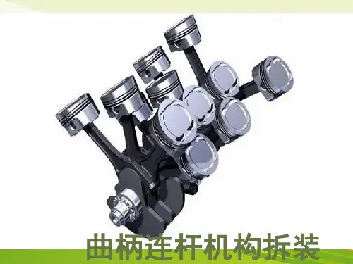
曲柄连杆机构的拆装
- 格式:ppt
- 大小:2.04 MB
- 文档页数:31
发动机曲柄连杆机构拆装第一篇:发动机曲柄连杆机构拆装曲柄连杆机构拆装步骤1、将发动机摇至垂直位置,按规定顺序分次交叉(由两边向中间最少三次)拆下十个气缸盖固定螺栓,将螺栓取出放好,小心拆下气缸盖并放置木块上,取下汽缸垫放好*按规定气缸盖螺栓、汽缸垫拆卸后应全部更换新的,这里不做要求,仍然继续使用。
2、将发动机摇至水平位置,转动曲轴,使一缸活塞处于下止点位置,分次拆下一缸连杆轴承螺栓,取下轴承盖,在连杆螺栓上安装保护套,防止刮伤气缸壁,然后取下活塞(注意不可用金属工具顶连杆轴瓦),将取下的活塞做好标记放置工作台,再转动曲轴按同样的方法拆下其余三个气缸的活塞,注意摆放顺序(活塞环不用取下)。
3、将发动机摇至倒立垂直位置,按规定顺序分次交叉(由两边向中间最少三次)拆下曲轴轴承盖、轴瓦、止推垫片放至工作台(注意曲轴轴承盖上的标记,安装时要按原来标记装回,轴瓦不能互换),取下曲轴,按要求摆放好。
*按规定曲轴轴承盖螺栓拆卸后应全部更换新的,这里不做要求,仍然继续使用。
4、需清洗部位:气缸盖上下平面、曲轴轴瓦、连杆轴瓦、活塞、曲轴、气缸、气缸体平面。
5、安装前需润滑部位:曲轴轴瓦、曲轴各轴颈、连杆轴瓦、气缸壁、活塞6、将发动机摇至倒立垂直位置,放上曲轴,将装好轴瓦的轴承盖放置原来位置,止推垫片按规定方向放好,按规定顺序分次交叉(由中间向两边最少三次)装上曲轴轴承盖,最后扭力为65N/m+1/4圈。
在拧紧螺栓过程中,每拧紧一对螺栓,应检查一次曲轴转动是否顺畅。
8、将发动机摇至水平位置,转动曲轴,使一缸连杆轴颈处于上止点位置,在连杆螺栓上安装保护套,将活塞环开口错开120°,将一缸活塞装入一缸(注意活塞头部剪头标记朝前,连杆轴承方向需和连杆方向一致,各缸活塞、连杆轴承、轴瓦应装回原来位置,不能互换),连杆螺栓扭力30N/m+1/4圈。
再转动曲轴按同样的方法拆安装其余三个气缸的活塞。
在安装活塞过程中,每拧紧一对连杆轴承螺栓,应检查一次曲轴转动是否顺畅。


曲柄连杆机构拆装步骤
一、前言
曲柄连杆机构是内燃机的重要组成部分,其结构复杂,需要进行定期
维护和检修。
本文将详细介绍曲柄连杆机构的拆装步骤。
二、准备工作
1. 工具准备:扳手、梅花扳手、卡尺、量具等;
2. 拆卸前应先清洁曲轴箱内部,以避免灰尘等杂物进入曲柄连杆机构;
3. 确保拆卸时车辆处于平稳状态,并采取必要的安全措施。
三、曲柄拆卸
1. 先将发动机从车辆中取出,并放置在工作台上;
2. 用梅花扳手卸下发动机正时链条或齿轮;
3. 用扳手拧下曲轴前端盖螺丝,并取下前端盖;
4. 用卡尺或量具测量曲轴主轴颈直径和圆度,如不符合规定尺寸应更
换新的曲轴。
四、连杆拆卸
1. 将连杆盖板螺丝依次拧下,并取下连杆盖板;
2. 用扳手拆下连杆螺栓,取下连杆和活塞组件;
3. 用卡尺或量具测量连杆轴颈直径和圆度,如不符合规定尺寸应更换新的连杆。
五、曲柄及连杆安装
1. 将新的曲轴放入曲轴箱中,并安装前端盖;
2. 安装曲轴前端盖螺丝,并用扳手拧紧;
3. 将新的连杆放入曲轴箱中,并用扳手拧上螺栓;
4. 用扭矩扳手按照规定扭矩拧紧螺栓;
5. 安装活塞组件,将连杆盖板安装在曲轴箱上,并依次拧紧螺丝。
六、总结
以上是曲柄连杆机构的拆装步骤,需要注意的是,在进行拆卸前应先清洁曲轴箱内部,以避免灰尘等杂物进入曲柄连杆机构。
在安装时要按照规定操作步骤进行操作,以确保发动机正常运转。
曲柄连杆机构的拆装流程英文回答:The disassembly and assembly process of a crank-connecting rod mechanism involves several steps. Let me walk you through the process.First, you need to remove any external components that may be attached to the crank-connecting rod mechanism. This could include things like bolts, covers, or protective plates. It's important to carefully keep track of these components and their positions for reassembly later.Next, you will need to separate the crankshaft from the connecting rod. This can be done by removing the bolts or pins that hold them together. Once they are separated, you can inspect them for any damage or wear.After that, you can proceed to remove the connecting rod from the piston. This is usually done by removing thebolts or pins that secure them. Be cautious when handling the connecting rod to avoid any damage.Once the connecting rod is detached from the piston, you can inspect both components for any signs of wear or damage. It's important to check the bearings and bushings for any excessive play or wear, as they may need to be replaced.Now that you have disassembled the crank-connecting rod mechanism, you can begin the reassembly process. Start by carefully aligning the connecting rod with the piston and securing them together with bolts or pins.Next, you will need to attach the crankshaft to the connecting rod. Make sure to align the journals properly and tighten the bolts or pins according to the manufacturer's specifications. It's important to ensure a proper fit to prevent any issues with the mechanism's operation.Finally, you can reattach any external components thatwere removed earlier. Double-check that everything is properly secured and tightened.中文回答:曲柄连杆机构的拆装流程涉及几个步骤。
1 教学整体设计1.1 对接典型工作任务,选择教学内容曲柄连杆机构是发动机的主要运动机构,也是导致发动机故障的主要部件,曲柄连杆机构的拆装是汽车维修岗位具有代表性的工作任务。
基于发动机维修工作过程,设置活塞连杆组和曲轴飞轮组的部件认知、拆卸、安装等6个任务,共计16个学时。
1.2 对接职业岗位标准,设置三维目标(1)基于职业岗位标准,设置三维目标。
根据专业人才培养方案,构建专业课程体系,依据汽车维修工国家职业标准和汽车领域1+X 职业技能等级标准,将爱岗敬业、安全规范、精益求精等工匠精神融入教学,细化人才培养规格,层层分解课程目标,制定曲柄连杆机构认知与拆装的三维教学目标(表1)。
(2)基于岗位能力需求,确定重点难点。
根据企业岗位调研,掌握曲柄连杆机构各部件的构造与功用是分析发动机故障的理论基础,各部件的规范拆装是完成发动机故障维修的重要基础性工作,也是汽车维修岗位必备的技能。
基于此,确定本项目的教学重点为:拆装工具的选择与使用;拆装工作流程及工艺标准。
教学难点为:曲柄连杆机构的工作原理;活塞环的选配;曲轴主轴承盖装配顺序的确定。
1.3 对接学情分析报告,制定教学策略本课程授课对象为汽车运用与维修专业高一年级学生,学生前期已学习了汽车文化和本课程模块一的内容,对发动机外围零部件和发动机相关名词术语有一定的认知。
通过问卷星对学生学习特点分析发现,学生有较强的求知欲和好奇心、能够积极参与讨论、能够围绕设定的问题积极思考、有强烈的表现欲、信息工具使用熟练、动手能力较强,但做事粗心、自控力及语言表达能力较差、分析问题的能力较弱、对理论知识学习缺乏兴趣、实习实训操作规范意识不强。
(1)基于真实工作案例,构建教学情境。
以汽车发动机的故障案例为切入点,以案例引入项目、教汽车发动机曲柄连杆机构认知与拆装的教学实施四川省剑阁职业高级中学校 王德明,侯继松,王治建表1 曲柄连杆机构认知与拆装的三维教学目标12师引导思路、学生主动参与的方式激发学生学习兴趣。

曲柄连杆机构拆装工艺流程英文回答:The disassembly and assembly process of a crankshaft connecting rod mechanism involves several steps to ensure the proper removal and installation of the components. Here is a detailed description of the process:1. Preparation: Before starting the disassembly process, it is important to gather all the necessary tools and equipment. This may include wrenches, pliers, a hammer, and a socket set. Additionally, it is crucial to have a clean and well-organized workspace to avoid losing any small parts.2. Disassembly: The first step in the disassembly process is to remove any external components that may be attached to the crankshaft connecting rod mechanism. This may include the piston, cylinder head, and oil pan. Once these components are removed, the next step is to loosenand remove the connecting rod bolts that attach the connecting rod to the crankshaft. This can be done by using a socket wrench or a breaker bar. Once the bolts are removed, the connecting rod can be separated from the crankshaft.3. Inspection: After the disassembly process, it is important to inspect all the components for any signs of wear or damage. This includes checking the crankshaft for any cracks or scoring, as well as inspecting the connecting rod for any signs of bending or damage. If any issues are found, the necessary repairs or replacements should be made before proceeding with the assembly process.4. Cleaning: Once the inspection is complete, it is important to thoroughly clean all the components before reassembly. This can be done by using a degreaser and a brush to remove any dirt, oil, or debris. It is important to ensure that all the components are completely dry before proceeding with the assembly process.5. Assembly: The assembly process involves reversingthe steps taken during the disassembly process. This includes attaching the connecting rod to the crankshaft and tightening the connecting rod bolts to the specified torque. It is important to refer to the manufacturer's guidelinesfor the proper torque specifications. Once the connecting rod is securely attached to the crankshaft, the external components, such as the piston, cylinder head, and oil pan, can be reinstalled.6. Testing: After the assembly process is complete, itis important to test the crankshaft connecting rod mechanism to ensure proper functionality. This can be done by manually rotating the crankshaft to check for any abnormalities or restrictions. Additionally, it isimportant to check for proper alignment and clearance between the components.In conclusion, the disassembly and assembly process ofa crankshaft connecting rod mechanism involves several steps, including preparation, disassembly, inspection, cleaning, assembly, and testing. By following these steps and paying attention to detail, the process can becompleted successfully.中文回答:曲柄连杆机构的拆装过程涉及多个步骤,以确保零件的正确拆卸和安装。
拖拉机曲柄连杆机构是发动机的基本传动机构。
曲柄连杆机构是将燃料燃烧的热能,通过活塞往复运动,传给曲轴变成旋转运动机械能的重要拖拉机配件,是构成拖拉机发动机的骨架。
在维修拖拉机时,拆装曲柄连杆机构应该注意以下八个事项:1、拆装时要注意清洁,不要刮伤零件的表面。
2、装活塞环时,应注意一般柴油机活塞上端第一道气环是镀铬的,其开口不要对着活塞顶部的涡流凹坑。
气环有切槽或倒角时,应使切槽或倒角朝上。
各活塞环开口要均匀错开。
3、连杆与活塞安装时,要注意连杆大头和活塞顶上的标志,不要把方向弄反了。
活塞连杆装入汽缸时,活塞顶上的涡流凹坑或燃烧室应与缸盖上的涡流室或喷油器对好。
4、曲轴与主轴瓦、连杆轴瓦,活塞与缸筒,活塞销和销孔都要分组选配,不同组的不能装在一起。
同一发动机每套活塞连杆组重量相差不得超过规定值。
5、曲轴经修磨,缸筒经搪缸后,均应按修理尺寸选用配套的轴瓦和活塞。
6、主轴承盖及连杆轴承盖都不要互相调换或改变方向装配。
连杆轴承盖的配套号和连杆配套号要装在同一边,而且号码要相同。
7、主轴承、连杆轴承和缸盖的螺栓(或螺母)等均应用扭力扳手按规定的扭矩分几次逐个交替拧紧。
在农业机械和园林机械维修中,拆装和装配都是十分重要的工序,拆卸质量将直接影响修理进程和成本,而装配质量则直接决定机械的使用寿命。
若乱拆硬装,就容易损坏农业园林机械。
因此,在拆卸和安装时,应严格按规程进行。
(“园林机械行业网收集整理”)1.采棉头倾斜度的调节通过调整采棉头大梁两侧的吊臂长度,使机器作业时前部滚筒比后部滚筒低19毫米,这使得摘锭接触更多的棉花并使残余物从采棉头底部流出去。
吊臂长度为销对销距离584毫米,两个提升框架应调整一致,倾斜度调整应在棉行内进行。
2.压紧板间隙的调节压力板和摘锭尖端之间的间距可以通过调节压力板铰链上的螺母调节,大约为3~6毫米,通过实践应调整到压力板和摘锭的尖端间隙为1毫米左右为好,间隙过大会漏棉花,间隙过小摘锭会在压力板上划出深槽,损坏部件。
学习单元2.2 曲柄连杆机构拆装与调整2.2.4拆卸活塞旋松连杆大头紧固螺母,取下螺母,取下连杆头轴承座。
用锤柄轻击连杆大头螺栓,顶出活塞,将连杆大头、轴承座装在一起。
如图2-2-3所示。
注意:将连杆按顺序摆放好,以便下一次复装。
图2-2-3拆卸活塞2.2.5拆卸曲轴取下正时齿轮、曲轴前后的油封端盖,旋松并取下曲轴主轴承盖,抬出曲轴,取出上轴瓦止推轴承。
如图2-2-4所示。
注意:不要跌落轴瓦,将轴承盖按顺序摆放好。
图2-2-4 曲轴的拆卸2.2.6活塞连杆组的拆卸1.用活塞环拆卸专业工具依次拆下活塞环。
如图2-2-5所示。
2.用尖嘴钳取出活塞销卡簧,用拇指压出活塞销,或用专用冲头将其冲出。
如图2-2-6所示。
3.取出连杆轴承。
4.按相反顺序复装活塞连杆组。
图2-2-5拆卸活塞环图2-2-6 拆卸卡簧注意:①对活塞做标记时,应从发动机前端向后打上气缸号,并打上指向发动机前端的箭头。
②拆卸连杆和连杆轴承盖时,应打上所属气缸号。
安装连杆时,浇铸的标记须朝V形带轮方向(发动机前方)③安装活塞环时,应使活塞环开口错开120度,有“TOP”记号的一面须朝活塞顶部。
2.2.7曲轴飞轮组的拆卸1.按对角顺序旋松飞轮固定螺栓,取下螺栓,用手锤沿四周轻轻敲击飞轮,待松动后取下飞轮。
如图2-2-7所示。
2.拧松并取下曲轴油封端盖紧固螺栓,用手锤轻轻敲击油封端盖,待松动后取下油封端盖。
如图2-2-7所示。
3.拆卸主轴承盖及止推轴承,抬出曲轴。
4.安装时按相反顺序逐步进行。
注意:在新油封唇部涂润滑脂,然后用专用油封安装工具和锤子敲入油封,直至其端面与油封边缘齐平。
图2-2-7油封的拆卸和安装2.2.8曲轴飞轮组的安装1.将飞轮安装于曲轴后端轴凸缘盘上,安装时注意原定位标记,然后紧固螺母。
螺母紧固时应对角交叉进行,并按扭紧力矩拧紧。
2.在曲轴主轴承座上安装并定位好轴承(轴承上油孔应与座上油道孔对准),然后在轴瓦表面涂上一层薄机油。