ASME 压力容器强度计算 PVELITE Table of Contents
- 格式:pdf
- 大小:118.25 KB
- 文档页数:47
第11章压力容器的强度计算本章重点要讲解内容:(1)理解内压容器设计时主要设计参数(容器内径、设计压力、设计温度、许用应力、焊缝系数等)的意义及其确定原则;(2)掌握五种厚度(计算壁厚、设计壁厚、名义壁厚、有效壁厚、最小壁厚)的概念、相互关系以及计算方法;能熟练地确定腐蚀裕度和钢板负偏差;(3)掌握内压圆筒的厚度设计;(4)掌握椭圆封头、锥形封头、半球形封头以及平板封头厚度的计算。
(5)熟悉内压容器强度校核的思路和过程。
第一节设计参数的确定1、我国压力容器标准与适用范围我国现执行GB150-98 “钢制压力容器”国家标准。
该标准为规则设计,采用弹性失效准则和稳定失效准则,应用解析法进行应力计算,比较简便。
JB4732-1995《钢制压力容器—分析设计标准》,其允许采用高的设计强度,相同设计条件下,厚度可以相应地减少,重量减轻。
其采用塑性失效准则、失稳失效准则和疲劳失效准则,计算比较复杂,和美国的ASME标准思路相似。
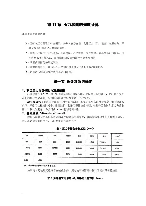
2、容器直径(diameter of vessel)考虑压制封头胎具的规格及标准件配套选用的需要,容器筒体和封头的直径都有规定。
对于用钢板卷制的筒体,以内径作为其公称直径。
表1 压力容器的公称直径(mm)如果筒体是使用无缝钢管直接截取的,规定使用钢管的外径作为筒体的公称直径。
表2 无缝钢管制作筒体时容器的公称直径(mm)3、设计压力(design pressure)(1)相关的基本概念(除了特殊注明的,压力均指表压力)✧工作压力P W:在正常的工作情况下,容器顶部可能达到的最高压力。
①由于最大工作压力是容器顶部的压力,所以对于塔类直立容器,直立进行水压试验的压力和卧置时不同;②工作压力是根据工艺条件决定的,容器顶部的压力和底部可能不同,许多塔器顶部的压力并不是其实际最高工作压力(the maximum allowable working pressure)。
③标准中的最大工作压力,最高工作压力和工作压力概念相同。

压力容器的强度计算第11章压力容器的强度计算本章重点要讲解内容:(1)理解内压容器设计时主要设计参数(容器内径、设计压力、设计温度、许用应力、焊缝系数等)的意义及其确定原则;(2)掌握五种厚度(计算壁厚、设计壁厚、名义壁厚、有效壁厚、最小壁厚)的概念、相互关系以及计算方法;能熟练地确定腐蚀裕度和钢板负偏差;(3)掌握内压圆筒的厚度设计;(4)掌握椭圆封头、锥形封头、半球形封头以及平板封头厚度的计算。
(5)熟悉内压容器强度校核的思路和过程。
第一节设计参数的确定1、我国压力容器标准与适用范围我国现执行GB150-98 “钢制压力容器”国家标准。
该标准为规则设计,采用弹性失效准则和稳定失效准则,应用解析法进行应力计算,比较简便。
JB4732-1995《钢制压力容器—分析设计标准》,其允许采用高的设计强度,相同设计条件下,厚度可以相应地减少,重量减轻。
其采用塑性失效准则、失稳失效准则和疲劳失效准则,计算比较复杂,和美国的ASME标准思路相似。
2、容器直径(diameter of vessel)考虑压制封头胎具的规格及标准件配套选用的需要,容器筒体和封头的直径都有规定。
对于用钢板卷制的筒体,以内径作为其公称直径。
表1 压力容器的公称直径(mm)如果筒体是使用无缝钢管直接截取的,规定使用钢管的外径作为筒体的公称直径。
表2 无缝钢管制作筒体时容器的公称直径(mm)3、设计压力(design pressure)(1)相关的基本概念(除了特殊注明的,压力均指表压力)工作压力P W:在正常的工作情况下,容器顶部可能达到的最高压力。
①由于最大工作压力是容器顶部的压力,所以对于塔类直立容器,直立进行水压试验的压力和卧置时不同;②工作压力是根据工艺条件决定的,容器顶部的压力和底部可能不同,许多塔器顶部的压力并不是其实际最高工作压力(the maximum allowableworking pressure)。
③标准中的最大工作压力,最高工作压力和工作压力概念相同。

设计计算书Design Calculation Sheet1. 设计参数和条件Design Data and Condition:1) 设计所遵循的规范Applicable Design Code:ASME SectionⅧ,Div.1, 20132) 设计压力(p) : 内部1.3MpaDesign Pressure (p): Internal 1.3 MPa3) 设计温度: 60℃Design Temperature: 60℃4) 焊接接头系数(E): 壳体为0.85,封头为0.85(无缝)Joint Efficiency (E): 0.85 for Shell and 0.85 for Heads(seamless)5) 材料最大许用应力Material Max. Allowable Stress:Based on ASME Code Sec.Ⅱ, Part D Table 1A壳体和封头: SA516 Gr. 485,60℃时为138MPaShell & Heads: SA516 Gr. 485 Material Max. Allowable Stress is 138MPa at 60℃;接管: SA105M钢,60℃时为138MPaNozzles:SA105M Steel Material Max. Allowable Stress 138 MPa at 60℃;6) 媒介: 空气Medium: Air (Non lethal)7) 封头类型: 2:1椭圆封头Head type: 2:1Ellipsoidal Head;8) 其他载荷: 依据“客户设计说明书”(Doc. No. TS-15-01 Rev.0)Others Loadings: As Shown in“Customer’s Design Specification”(Doc. No. TS-15-01 Rev. 0)9) 腐蚀余度:2.0 mmCorrosion Allowance: 2.0 mm10) 容器外形和尺寸:依据“客户设计说明书”(Doc. No. TS-15-01 Rev.0)Layout of Vessel and Dimension:As Shown in“Customer’s Design Specification”(Doc. No. TS-15-01 Rev. 0) 11) 钢印要求: 要求ASME标识Stamp required: ASME Certification Mark required12) NB要求: 不要求NB钢印NB stamp required: NO “NB” stamp required.Verify for UG-22 LoadingPressure符号 Symbols:t= 壳体要求最小厚度,mmt = minimum required thickness of shell, mm P = 内部设计压力, 1.3MPaP = internal design pressure, 1.3 MPa [see UG-21] R = 预计容器筒内半径, 250mmR = inside radius of the shell course under consideration, 250mm S = 最大许用应力值,138MPaS = maximum allowable stress value, 138MPa [ see ASME Code Part II DTable 1A for material SA-516 Gr.485] E = 焊接接头系数,0.85E = joint efficiency, 0.85 [see Table UW-12(1)]Since P=1.3MPa is less than 0.385SE=45.16MPa, Formula UG-27(c)(1) is used:)(2.811.36.085.0381)2025(3.16.0mm P SE PR t =⨯-⨯+⨯=-=考虑腐蚀裕量:Consider of corrosion allowable: tr= t + Ca = 2.81 + 2.0 = 4.81mmThese formulas will govern only when the circumferential joint efficiency is less than one-half the longitudinal joint efficiency, according to UG-27(c) (2) note 20, the formula UG-27(c) (2) for longitudinal stress needn’t considered. 公称钢板规则厚度=10mmNominal Plate Thickness Ordered = 10 mm钢板厚度可允许下偏差=0.25mm[see UG-16(c)] Plate Under tolerance=0.25 mm [ see UG-16(c)]UG-16 (b)(4) the minimum thickness of pressure retaining components >2.5mm for air service(exclusive any corrosion allowance). 实际使用厚度=10-0.25=9.75> 4.81mm ,并且也>2.5+2mm,可以。

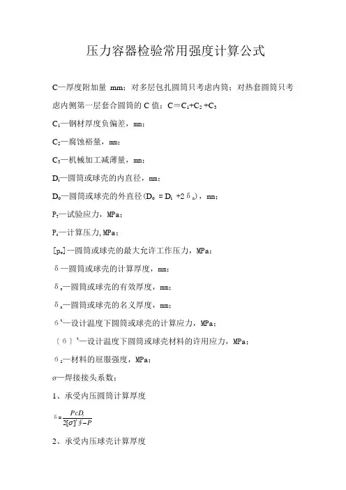
压力容器检验常用强度计算公式C —厚度附加量mm ;对多层包扎圆筒只考虑内筒;对热套圆筒只考虑内侧第一层套合圆筒的C 值;C =C 1+C 2 +C 3C 1—钢材厚度负偏差,mm ;C 2—腐蚀裕量,mm ;C 3—机械加工减薄量,mm ;D i —圆筒或球壳的内直径,mm ;D o —圆筒或球壳的外直径(D o = D i +2δn ),mm ;P T —试验应力,MPa ;P c —计算压力,MPa ;[p w ]—圆筒或球壳的最大允许工作压力,MPa ;δ—圆筒或球壳的计算厚度,mm ;δe —圆筒或球壳的有效厚度,mm ;δn —圆筒或球壳的名义厚度,mm ;бt —设计温度下圆筒或球壳的计算应力,MPa ;〔б〕t —设计温度下圆筒或球壳材料的许用应力,MPa ; бs —材料的屈服强度,MPa ;ø—焊接接头系数;1、承受内压圆筒计算厚度δ=PPcD t i -∮][2σ 2、承受内压球壳计算厚度δ=PPcD t i -∮][4σ 3、承受内压椭圆形封头计算厚度a )标准椭圆形封头δ=PPcD t i 5.0∮][2-σ b )非标准椭圆形封头δ=PkPcD t i 5.0∮][2-σ ])2(2[612ii h D k += 2、应力校核a 、液压试验时,圆筒的薄膜应力校核бT =ee D P i T δδ2)(+《0.9бs ø b 、气压试验时,圆筒的薄膜应力校核бT =ee D P i T δδ2)(+《0.8бs ø c 、液压试验时,球形容器的薄膜应力校核бT =ee D P i T δδ4)(+《0.9бs ø d 、气压试验时,球形容器的薄膜应力校核бT =ee D P i T δδ4)(+《0.8бs ø 3、最大允许工作压力计算a 、圆筒最大允许工作压力计算〔P w 〕=ei t e D δσδ+Φ][2b 、球壳最大工作压力〔P w 〕=ei t e D δσδ+Φ][4 4、内压容器试验压力液压试验 P T =1.25Pt ][][σσ 气压试验 P T =1.25P t][][σσ 对在用压力容器P 指最高工作压力,MPa5、容器开孔及开孔补强(本题2004年压力容器检验师考试考过) a 、开孔削弱面积A内压圆筒体与球壳A =d δ+2δδet (1-f r )d —考虑腐蚀后的开孔直径,d =d i +2Cδet —接管名义厚度C —壁厚附加量f r —强度削弱系数。
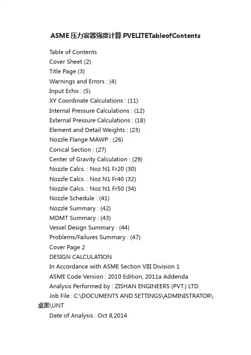
ASME压力容器强度计算PVELITETableofContentsTable of ContentsCover Sheet (2)Title Page (3)Warnings and Errors : (4)Input Echo : (5)XY Coordinate Calculations : (11)Internal Pressure Calculations : (12)External Pressure Calculations : (18)Element and Detail Weights : (23)Nozzle Flange MAWP : (26)Conical Section : (27)Center of Gravity Calculation : (29)Nozzle Calcs. : Noz N1 Fr20 (30)Nozzle Calcs. : Noz N1 Fr40 (32)Nozzle Calcs. : Noz N1 Fr50 (34)Nozzle Schedule : (41)Nozzle Summary : (42)MDMT Summary : (43)Vessel Design Summary : (44)Problems/Failures Summary : (47)Cover Page 2DESIGN CALCULATIONIn Accordance with ASME Section VIII Division 1ASME Code Version : 2010 Edition, 2011a AddendaAnalysis Performed by : ZISHAN ENGINEERS (PVT.) LTD.Job File : C:\DOCUMENTS AND SETTINGS\ADMINISTRATOR\桌面\UNTDate of Analysis : Oct 8,2014PV Elite 2012, January 2012Title Page 3Warnings and Errors : Step: 0 2:56p Oct 8,2014Class From To : Basic Element Checks.====================================== ==================================== Warn. 30 40 Inconsistent external pressure definition. The givenexternal pressure was not the same as the internal pressure on thefollowing element.Class From To: Check of Additional Element Data====================================== ==================================== Warn 30 40 Check UG-32(j) and UG-81 for Crown Radius > ODPV Elite is a trademark of Intergraph CADWorx & Analysis Solutions, Inc. 2012Input Echo : Step: 1 2:56p Oct 8,2014 PV Elite Vessel Analysis Program: Input DataDesign Internal Pressure (for Hydrotest) 100.00 psigDesign Internal Temperature 200 FType of Hydrotest not SpecifiedHydrotest Position HorizontalProjection of Nozzle from Vessel Top 0.0000 in.Projection of Nozzle from Vessel Bottom 0.0000 in.Minimum Design Metal Temperature -20 FType of Construction WeldedSpecial Service NoneDegree of Radiography RT 1Miscellaneous Weight Percent 0.0Use Higher Longitudinal Stresses (Flag) YSelect t for Internal Pressure (Flag) NSelect t for External Pressure (Flag) NSelect t for Axial Stress (Flag) NSelect Location for Stiff. Rings (Flag) NConsider Vortex Shedding YPerform a Corroded Hydrotest NIs this a Heat Exchanger NoUser Defined Hydro. Press. (Used if > 0) 0.0000 psig User defined MAWP 0.0000 psigUser defined MAPnc 0.0000 psigLoad Case 1 NP+EW+WI+FW+BWLoad Case 2 NP+EW+EE+FS+BSLoad Case 3 NP+OW+WI+FW+BWLoad Case 4 NP+OW+EQ+FS+BSLoad Case 5 NP+HW+HILoad Case 6 NP+HW+HELoad Case 7 IP+OW+WI+FW+BWLoad Case 8 IP+OW+EQ+FS+BSLoad Case 9 EP+OW+WI+FW+BWLoad Case 10 EP+OW+EQ+FS+BSLoad Case 11 HP+HW+HILoad Case 12 HP+HW+HELoad Case 13 IP+WE+EWLoad Case 14 IP+WF+CWLoad Case 15 IP+VO+OWLoad Case 16 IP+VE+EWLoad Case 17 NP+VO+OWLoad Case 18 FS+BS+IP+OWLoad Case 19 FS+BS+EP+OW。
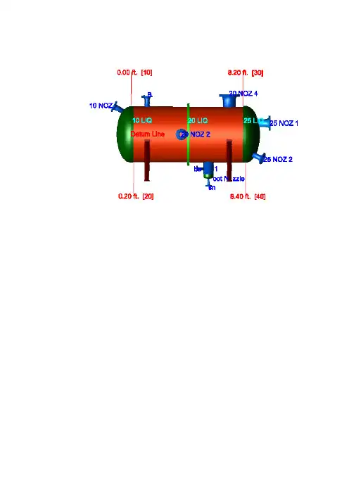
Table of ContentsCover Sheet (3)Title Page (4)Warnings and Errors : (5)Input Echo : (6)XY Coordinate Calculations : (15)Internal Pressure Calculations : (16)External Pressure Calculations : (22)Element and Detail Weights : (27)Nozzle Flange MAWP : (30)Wind Load Calculation : (31)Earthquake Load Calculation : (34)Center of Gravity Calculation : (35)Horizontal Vessel Analysis (Ope.) : (36)Horizontal Vessel Analysis (Test) : (44)Nozzle Calcs. : 10 NOZ (51)Nozzle Calcs. : B (58)Nozzle Calcs. : 20 NOZ 2 (66)Nozzle Calcs. : Boot Nozzle (74)Nozzle Calcs. : 20 NOZ 4 (81)Nozzle Calcs. : boot_n1 (88)Nozzle Calcs. : 25 NOZ 1 (92)Nozzle Calcs. : 25 NOZ 2 (104)Nozzle Calcs. : sn (112)Nozzle Schedule : (116)Nozzle Summary : (118)MDMT Summary : (120)Vessel Design Summary : (122)DESIGN CALCULATIONIn Accordance with ASME Section VIII Division 1ASME Code Version : 1998, Addenda A-98Analysis Performed by : ZISHAN ENGINEERS (PVT.) LTD.Job File : D:\PVELITE 2015\EXAMPLES_BACKUP\HORIZ1.PVDB Date of Analysis : Aug 18,2016PV Elite 2015, January 2014Class From To : Basic Element Checks.==========================================================================Class From To: Check of Additional Element Data========================================================================== There were no geometry errors or warnings.PV Elite is a trademark of Intergraph CADWorx & Analysis Solutions, Inc. 2014PV Elite Vessel Analysis Program: Input DataDesign Internal Pressure (for Hydrotest) 300.00 psig Design Internal Temperature 450 FType of Hydrotest UG-99(c)Hydrotest Position HorizontalProjection of Nozzle from Vessel Top 0.0000 in. Projection of Nozzle from Vessel Bottom 0.0000 in. Minimum Design Metal Temperature 0 FType of Construction Resist. WeldedSpecial Service NonstationaryDegree of Radiography RT 4Miscellaneous Weight Percent 0.0Use Higher Longitudinal Stresses (Flag) YSelect t for Internal Pressure (Flag) YSelect t for External Pressure (Flag) NSelect t for Axial Stress (Flag) NSelect Location for Stiff. Rings (Flag) NConsider Vortex Shedding NPerform a Corroded Hydrotest NIs this a Heat Exchanger NoUser Defined Hydro. Press. (Used if > 0) 0.0000 psig User defined MAWP 0.0000 psigUser defined MAPnc 0.0000 psigLoad Case 1 NP+EW+WI+BWLoad Case 2 NP+EW+EQ+BSLoad Case 3 NP+OW+WI+BWLoad Case 4 NP+OW+EQ+BSLoad Case 5 NP+HW+HILoad Case 6 NP+HW+HELoad Case 7 IP+OW+WI+BWLoad Case 8 IP+OW+EQ+BSLoad Case 9 EP+OW+WI+BWLoad Case 10 EP+OW+EQ+BSLoad Case 11 HP+HW+HILoad Case 12 HP+HW+HEWind Design Code ASCE-7 95Basic Wind Speed [V] 70.000 mile/hr Surface Roughness Category C: Open TerrainImportance Factor 1.0Type of Surface Moderately SmoothBase Elevation 0.0000 ft.Percent Wind for Hydrotest 20.0Using User defined Wind Press. Vs Elev. NHeight of Hill or Escarpment H or Hh 0.0000 ft. Distance Upwind of Crest Lh 0.0000 ft. Distance from Crest to the Vessel x 0.0000 ft. Type of Terrain ( Hill, Escarpment ) FlatDamping Factor (Beta) for Wind (Ope) 0.0100Damping Factor (Beta) for Wind (Empty) 0.0200Damping Factor (Beta) for Wind (Filled) 0.0000Seismic Design Code ASCE 7-88Seismic Zone 0.000Importance Factor 1.000Soil Type S1Horizontal Force Factor 2.000Percent Seismic for Hydrotest 0.000Design Nozzle for Des. Press. + St. Head YConsider MAP New and Cold in Noz. Design NConsider External Loads for Nozzle Des. NUse ASME VIII-1 Appendix 1-9 NMaterial Database Year 1997 Configuration Directives:Do not use Nozzle MDMT Interpretation VIII-1 01-37 NoUse Table G instead of exact equation for "A" NoShell Head Joints are Tapered NoCompute "K" in corroded condition NoUse Code Case 2286 NoUse the MAWP to compute the MDMT NoUsing Metric Material Databases, ASME II D No Complete Listing of Vessel Elements and Details:Element From Node 10Element To Node 20Element Type EllipticalDescriptionDistance "FROM" to "TO" 0.2000 ft.Inside Diameter 48.000 in.Element Thickness 0.7500 in.Internal Corrosion Allowance 0.05000 in. Nominal Thickness 0.0000 in.External Corrosion Allowance 0.0000 in. Design Internal Pressure 300.00 psig Design Temperature Internal Pressure 450 FDesign External Pressure 15.000 psigDesign Temperature External Pressure 70 FEffective Diameter Multiplier 1.2Material Name SA283-AAllowable Stress, Ambient 11300. psiAllowable Stress, Operating 11300. psiAllowable Stress, Hydrotest 16950. psiMaterial Density 0.2830 lb./cu.in.P Number Thickness 1.2500 in.Yield Stress, Operating 36000. psiUCS-66 Chart Curve Designation BExternal Pressure Chart Name CS-1UNS NumberProduct Form PlateEfficiency, Longitudinal Seam 1.0Efficiency, Circumferential Seam 1.0Elliptical Head Factor 2.0Element From Node 10Detail Type LiquidDetail ID 10 LIQDist. from "FROM" Node / Offset dist 0.0000 ft.Height/Length of Liquid 3.0000 ft.Liquid Density 22.500 lb./cu.ft.Element From Node 10Detail Type NozzleDetail ID 10 NOZDist. from "FROM" Node / Offset dist 20.000 in.Nozzle Diameter 4.0 in.Nozzle Schedule 80Nozzle Class 300Layout Angle 0.0Blind Flange (Y/N) NWeight of Nozzle ( Used if > 0 ) 0.0000 lb.Grade of Attached Flange GR 1.1Nozzle Matl SA-106 B--------------------------------------------------------------------Element From Node 20Element To Node 30Element Type CylinderDescriptionDistance "FROM" to "TO" 8.0000 ft.Inside Diameter 48.000 in.Element Thickness 0.5000 in.Internal Corrosion Allowance 0.05000 in.Nominal Thickness 0.0000 in.External Corrosion Allowance 0.0000 in.Design Internal Pressure 300.00 psigDesign Temperature Internal Pressure 450 FDesign External Pressure 15.000 psigDesign Temperature External Pressure 70 FEffective Diameter Multiplier 1.2Material Name SA283-AEfficiency, Longitudinal Seam 1.0Efficiency, Circumferential Seam 1.0Element From Node 20Detail Type SaddleDetail ID SADDLE 1Dist. from "FROM" Node / Offset dist 1.0000 ft.Width of Saddle 4.0000 in.Height of Saddle at Bottom 40.000 in.Saddle Contact Angle 150.0Height of Composite Ring Stiffener 0.2500 in.Width of Wear Plate 5.0000 in.Thickness of Wear Plate 0.1250 in.Contact Angle, Wear Plate (degrees) 160.0Element From Node 20Detail Type SaddleDetail ID SADDLE 2Dist. from "FROM" Node / Offset dist 7.0000 ft.Width of Saddle 4.0000 in.Height of Saddle at Bottom 40.000 in.Saddle Contact Angle 150.0Height of Composite Ring Stiffener 0.2500 in.Width of Wear Plate 5.0000 in.Thickness of Wear Plate 0.1250 in.Contact Angle, Wear Plate (degrees) 160.0Element From Node 20Detail Type LiquidDetail ID 20 LIQDist. from "FROM" Node / Offset dist 0.0000 ft.Height/Length of Liquid 3.0000 ft.Liquid Density 22.500 lb./cu.ft.Element From Node 20Detail Type RingDetail ID RINGDist. from "FROM" Node / Offset dist 4.0000 ft.Inside Diameter of Ring 48.000 in.Thickness of Ring 2.0000 in.Outside Diameter of Ring 55.000 in.Material Name SA-516 70Height of Section Ring 0.0000 in.Using Custom Stiffener Section NoElement From Node 20Detail Type NozzleDetail ID BDist. from "FROM" Node / Offset dist 1.0000 ft. Nozzle Diameter 4.0 in.Nozzle Schedule 40Nozzle Class 300Layout Angle 0.0Blind Flange (Y/N) NWeight of Nozzle ( Used if > 0 ) 100.00 lb. Grade of Attached Flange GR 1.1Nozzle Matl SA-106 BElement From Node 20Detail Type NozzleDetail ID 20 NOZ 2Dist. from "FROM" Node / Offset dist 3.5000 ft. Nozzle Diameter 4.0 in.Nozzle Schedule 80Nozzle Class 300Layout Angle 90.0Blind Flange (Y/N) NWeight of Nozzle ( Used if > 0 ) 0.0000 lb. Grade of Attached Flange GR 1.1Nozzle Matl SA-106 BElement From Node 20Detail Type NozzleDetail ID Boot NozzleDist. from "FROM" Node / Offset dist 5.5000 ft. Nozzle Diameter 8.0 in.Nozzle Schedule 80Nozzle Class NoneLayout Angle 180.0Blind Flange (Y/N) NWeight of Nozzle ( Used if > 0 ) 0.0000 lb. Grade of Attached Flange NoneNozzle Matl SA-106 BElement From Node 20Detail Type NozzleDetail ID 20 NOZ 4Dist. from "FROM" Node / Offset dist 7.0000 ft.Nozzle Diameter 10.0 in.Nozzle Schedule 80Nozzle Class 300Layout Angle 0.0Blind Flange (Y/N) NWeight of Nozzle ( Used if > 0 ) 0.0000 lb.Grade of Attached Flange GR 1.1Nozzle Matl SA-106 BElement From Node 20Detail Type NozzleDetail ID boot_n1Dist. from "FROM" Node / Offset dist 0.5000 ft.Nozzle Diameter 1.5 in.Nozzle Schedule 80Nozzle Class 300Layout Angle 180.0Blind Flange (Y/N) NWeight of Nozzle ( Used if > 0 ) 0.0000 lb.Grade of Attached Flange GR 1.1Nozzle Matl SA-106 BElement From Node 20Detail Type WeightDetail ID 20 WEIDist. from "FROM" Node / Offset dist 2.0000 ft.Miscellaneous Weight 10000. lb.Offset from Element Centerline 0.0000 in.Element From Node 20Detail Type For./Mom.Detail ID 20 FORDist. from "FROM" Node / Offset dist 6.0000 ft.Force in X Direction 10000. lb.Force in Y Direction 0.0000 lb.Force in Z Direction 0.0000 lb.Moment about X Axis 0.0000 ft.lb.Moment about Y Axis 0.0000 ft.lb.Moment about Z Axis 0.0000 ft.lb.Force/Moment Combination Method SRSS-------------------------------------------------------------------- Element From Node 30Element To Node 40Element Type EllipticalDescriptionDistance "FROM" to "TO" 0.2000 ft.Inside Diameter 48.000 in.Element Thickness 0.7500 in.Internal Corrosion Allowance 0.05000 in.Nominal Thickness 0.0000 in.External Corrosion Allowance 0.0000 in.Design Internal Pressure 300.00 psigDesign Temperature Internal Pressure 450 FDesign External Pressure 15.000 psigDesign Temperature External Pressure 70 FEffective Diameter Multiplier 1.2Material Name SA283-AEfficiency, Longitudinal Seam 1.0Efficiency, Circumferential Seam 1.0Elliptical Head Factor 2.0Element From Node 30Detail Type LiquidDetail ID 25 LIQDist. from "FROM" Node / Offset dist 0.0000 ft.Height/Length of Liquid 3.0000 ft.Liquid Density 22.500 lb./cu.ft.Element From Node 30Detail Type NozzleDetail ID 25 NOZ 1Dist. from "FROM" Node / Offset dist 10.000 in.Nozzle Diameter 6.0 in.Nozzle Schedule 80Nozzle Class 300Layout Angle 0.0Blind Flange (Y/N) NWeight of Nozzle ( Used if > 0 ) 0.0000 lb.Grade of Attached Flange GR 1.1Nozzle Matl SA106-BElement From Node 30Detail Type NozzleDetail ID 25 NOZ 2Dist. from "FROM" Node / Offset dist 20.000 in.Nozzle Diameter 4.0 in.Nozzle Schedule 80Nozzle Class 300Layout Angle 150.0Blind Flange (Y/N) NWeight of Nozzle ( Used if > 0 ) 0.0000 lb.Grade of Attached Flange GR 1.1Nozzle Matl SA-106 B--------------------------------------------------------------------Element From Node 40Element To Node 50Element Type EllipticalDescription Boot headDistance "FROM" to "TO" 0.2000 ft.Inside Diameter 7.9810 in.Element Thickness 0.3220 in.Internal Corrosion Allowance 0.05000 in.Nominal Thickness 0.0000 in.External Corrosion Allowance 0.0000 in.Design Internal Pressure 300.00 psigDesign Temperature Internal Pressure 450 FDesign External Pressure 15.000 psigDesign Temperature External Pressure 70 FEffective Diameter Multiplier 1.2Material Name SA283-AEfficiency, Longitudinal Seam 1.0Efficiency, Circumferential Seam 1.0Elliptical Head Factor 2.0Element From Node 40Detail Type LiquidDetail ID SUMP LIQDist. from "FROM" Node / Offset dist -0.1663 ft.Height/Length of Liquid 0.3663 ft.Liquid Density 22.464 lb./cu.ft.Element From Node 40Detail Type NozzleDetail ID snDist. from "FROM" Node / Offset dist 0.0000 in.Nozzle Diameter 1.0 in.Nozzle Schedule 160Nozzle Class 300Layout Angle 0.0Blind Flange (Y/N) NWeight of Nozzle ( Used if > 0 ) 0.0000 lb.Grade of Attached Flange GR 1.1Nozzle Matl SA-106 BPV Elite is a trademark of Intergraph CADWorx & Analysis Solutions, Inc. 2014XY Coordinate Calculations| | | | | |From| To | X (Horiz.)| Y (Vert.) |DX (Horiz.)| DY (Vert.) | | | ft. | ft. | ft. | ft. |-------------------------------------------------------------- 10| 20| 0.20000 | ... | 0.20000 | ... |20| 30| 8.20000 | ... | 8.00000 | ... |30| 40| 8.40000 | ... | 0.20000 | ... |Boot head| 5.70000 | -2.83333 | ... | 0.20000 |PV Elite is a trademark of Intergraph CADWorx & Analysis Solutions, Inc. 2014Element Thickness, Pressure, Diameter and Allowable Stress :| | Int. Press | Nominal | Total Corr| Element | Allowable |From| To | + Liq. Hd | Thickness | Allowance | Diameter | Stress(SE)|| | psig | in. | in. | in. | psi |--------------------------------------------------------------------------- 10| 20| 300.469 | ... | 0.050000 | 48.0000 | 11300.0 |20| 30| 300.469 | ... | 0.050000 | 48.0000 | 17500.0 |30| 40| 300.469 | ... | 0.050000 | 48.0000 | 11300.0 |Boot head| 300.624 | ... | 0.050000 | 7.98100 | 11300.0 | Element Required Thickness and MAWP :| | Design | M.A.W.P. | M.A.P. | Minimum | Required |From| To | Pressure | Corroded | New & Cold | Thickness | Thickness || | psig | psig | psig | in. | in. |---------------------------------------------------------------------------- 10| 20| 300.000 | 322.784 | 352.025 | 0.75000 | 0.69120 |20| 30| 300.000 | 323.338 | 360.082 | 0.50000 | 0.46723 |30| 40| 300.000 | 322.784 | 352.025 | 0.75000 | 0.69120 |Boot head| 300.000 | 730.567 | 904.517 | 0.32200 | 0.15778 |Minimum 322.784 352.024MAWP: 322.784 psig, limited by: Elliptical Head.Internal Pressure Calculation Results :ASME Code, Section VIII, Division 1, 1998, Code A-98 AddendaElliptical Head From 10 To 20 SA283-A , UCS-66 Crv. B at 450 FRequired Thickness due to Internal Pressure [tr]:= (P*D*K)/(2*S*E-0.2*P) Appendix 1-4(c)= (300.469*48.1000*1.000)/(2*11300.00*1.00-0.2*300.469)= 0.6412 + 0.0500 = 0.6912 in.Max. Allowable Working Pressure at given Thickness, corroded [MAWP]:Less Operating Hydrostatic Head Pressure of 0.469 psig= (2*S*E*t)/(K*D+0.2*t) per Appendix 1-4 (c)= (2*11300.00*1.00*0.7000)/(1.000*48.1000+0.2*0.7000)= 327.944 - 0.469 = 327.474 psigMaximum Allowable Pressure, New and Cold [MAPNC]:= (2*S*E*t)/(K*D+0.2*t) per Appendix 1-4 (c)= (2*11300.00*1.00*0.7500)/(1.000*48.0000+0.2*0.7500)= 352.025 psigActual stress at given pressure and thickness, corroded [Sact]:= (P*(K*D+0.2*t))/(2*E*t)= (300.469*(1.000*48.1000+0.2*0.7000))/(2*1.00*0.7000)= 10353.316 psiStraight Flange Required Thickness:= (P*R)/(S*E-0.6*P) + c per UG-27 (c)(1)= (300.469*24.0500)/(11300.00*1.00-0.6*300.469)+0.050= 0.700 in.Straight Flange Maximum Allowable Working Pressure:Less Operating Hydrostatic Head Pressure of 0.469 psig= (S*E*t)/(R+0.6*t) per UG-27 (c)(1)= (11300.00 * 1.00 * 0.7000 )/(24.0500 + 0.6 * 0.7000 )= 323.253 - 0.469 = 322.784 psigPercent Elong. per UCS-79, VIII-1-01-57 (75*tnom/Rf)*(1-Rf/Ro) 6.591 % Note: Please Check Requirements of UCS-79 as Elongation is > 5%.MDMT Calculations in the Knuckle Portion:Govrn. thk, tg = 0.750 , tr = 0.641 , c = 0.0500 in. , E* = 1.00Stress Ratio = tr * (E*)/(tg - c) = 0.916 , Temp. Reduction = 8 FMin Metal Temp. w/o impact per UCS-66, Curve B 16 FMin Metal Temp. at Required thickness (UCS 66.1) 8 FMin Metal Temp. w/o impact per UG-20(f) -20 FMDMT Calculations in the Head Straight Flange:Govrn. thk, tg = 0.750 , tr = 0.650 , c = 0.0500 in. , E* = 1.00Stress Ratio = tr * (E*)/(tg - c) = 0.928 , Temp. Reduction = 7 FMin Metal Temp. w/o impact per UCS-66, Curve B 16 FMin Metal Temp. at Required thickness (UCS 66.1) 9 FMin Metal Temp. w/o impact per UG-20(f) -20 FCylindrical Shell From 20 To 30 SA283-A , UCS-66 Crv. B at 450 FRequired Thickness due to Internal Pressure [tr]:= (P*R)/(S*E-0.6*P) per UG-27 (c)(1)= (300.469*24.0500)/(17500.00*1.00-0.6*300.469)= 0.4172 + 0.0500 = 0.4672 in.Max. Allowable Working Pressure at given Thickness, corroded [MAWP]:Less Operating Hydrostatic Head Pressure of 0.469 psig= (S*E*t)/(R+0.6*t) per UG-27 (c)(1)= (17500.00*1.00*0.4500)/(24.0500+0.6*0.4500)= 323.808 - 0.469 = 323.338 psigMaximum Allowable Pressure, New and Cold [MAPNC]:= (S*E*t)/(R+0.6*t) per UG-27 (c)(1)= (17500.00*1.00*0.5000)/(24.0000+0.6*0.5000)= 360.082 psigActual stress at given pressure and thickness, corroded [Sact]:= (P*(R+0.6*t))/(E*t)= (300.469*(24.0500+0.6*0.4500))/(1.00*0.4500)= 16238.701 psiPercent Elongation per UCS-79 (50*tnom/Rf)*(1-Rf/Ro) 1.031 %Minimum Design Metal Temperature Results:Govrn. thk, tg = 0.500 , tr = 0.417 , c = 0.0500 in. , E* = 1.00Stress Ratio = tr * (E*)/(tg - c) = 0.927 , Temp. Reduction = 7 FMin Metal Temp. w/o impact per UCS-66, Curve B -6 F Min Metal Temp. at Required thickness (UCS 66.1) -14 F Min Metal Temp. w/o impact per UG-20(f) -20 FElliptical Head From 30 To 40 SA283-A , UCS-66 Crv. B at 450 FRequired Thickness due to Internal Pressure [tr]:= (P*D*K)/(2*S*E-0.2*P) Appendix 1-4(c)= (300.469*48.1000*1.000)/(2*11300.00*1.00-0.2*300.469)= 0.6412 + 0.0500 = 0.6912 in.Max. Allowable Working Pressure at given Thickness, corroded [MAWP]:Less Operating Hydrostatic Head Pressure of 0.469 psig= (2*S*E*t)/(K*D+0.2*t) per Appendix 1-4 (c)= (2*11300.00*1.00*0.7000)/(1.000*48.1000+0.2*0.7000)= 327.944 - 0.469 = 327.474 psigMaximum Allowable Pressure, New and Cold [MAPNC]:= (2*S*E*t)/(K*D+0.2*t) per Appendix 1-4 (c)= (2*11300.00*1.00*0.7500)/(1.000*48.0000+0.2*0.7500)= 352.025 psigActual stress at given pressure and thickness, corroded [Sact]:= (P*(K*D+0.2*t))/(2*E*t)= (300.469*(1.000*48.1000+0.2*0.7000))/(2*1.00*0.7000)= 10353.316 psiStraight Flange Required Thickness:= (P*R)/(S*E-0.6*P) + c per UG-27 (c)(1)= (300.469*24.0500)/(11300.00*1.00-0.6*300.469)+0.050= 0.700 in.Straight Flange Maximum Allowable Working Pressure:Less Operating Hydrostatic Head Pressure of 0.469 psig= (S*E*t)/(R+0.6*t) per UG-27 (c)(1)= (11300.00 * 1.00 * 0.7000 )/(24.0500 + 0.6 * 0.7000 )= 323.253 - 0.469 = 322.784 psigPercent Elong. per UCS-79, VIII-1-01-57 (75*tnom/Rf)*(1-Rf/Ro) 6.591 % Note: Please Check Requirements of UCS-79 as Elongation is > 5%.MDMT Calculations in the Knuckle Portion:Govrn. thk, tg = 0.750 , tr = 0.641 , c = 0.0500 in. , E* = 1.00Stress Ratio = tr * (E*)/(tg - c) = 0.916 , Temp. Reduction = 8 FMin Metal Temp. w/o impact per UCS-66, Curve B 16 FMin Metal Temp. at Required thickness (UCS 66.1) 8 FMin Metal Temp. w/o impact per UG-20(f) -20 FMDMT Calculations in the Head Straight Flange:Govrn. thk, tg = 0.750 , tr = 0.650 , c = 0.0500 in. , E* = 1.00Stress Ratio = tr * (E*)/(tg - c) = 0.928 , Temp. Reduction = 7 FMin Metal Temp. w/o impact per UCS-66, Curve B 16 FMin Metal Temp. at Required thickness (UCS 66.1) 9 FMin Metal Temp. w/o impact per UG-20(f) -20 FElliptical Head From 40 To 50 SA283-A , UCS-66 Crv. A at 450 FBoot headRequired Thickness due to Internal Pressure [tr]:= (P*D*K)/(2*S*E-0.2*P) Appendix 1-4(c)= (300.624*8.0810*1.000)/(2*11300.00*1.00-0.2*300.624)= 0.1078 + 0.0500 = 0.1578 in.Max. Allowable Working Pressure at given Thickness, corroded [MAWP]:Less Operating Hydrostatic Head Pressure of 0.624 psig= (2*S*E*t)/(K*D+0.2*t) per Appendix 1-4 (c)= (2*11300.00*1.00*0.2720)/(1.000*8.0810+0.2*0.2720)= 755.611 - 0.624 = 754.987 psigMaximum Allowable Pressure, New and Cold [MAPNC]:= (2*S*E*t)/(K*D+0.2*t) per Appendix 1-4 (c)= (2*11300.00*1.00*0.3220)/(1.000*7.9810+0.2*0.3220)= 904.517 psigActual stress at given pressure and thickness, corroded [Sact]:= (P*(K*D+0.2*t))/(2*E*t)= (300.624*(1.000*8.0810+0.2*0.2720))/(2*1.00*0.2720)= 4495.764 psiStraight Flange Required Thickness:= (P*R)/(S*E-0.6*P) + c per UG-27 (c)(1)= (300.624*4.0405)/(11300.00*1.00-0.6*300.624)+0.050= 0.159 in.Straight Flange Maximum Allowable Working Pressure:Less Operating Hydrostatic Head Pressure of 0.598 psig= (S*E*t)/(R+0.6*t) per UG-27 (c)(1)= (11300.00 * 1.00 * 0.2720 )/(4.0405 + 0.6 * 0.2720 )= 731.165 - 0.598 = 730.567 psigPercent Elong. per UCS-79, VIII-1-01-57 (75*tnom/Rf)*(1-Rf/Ro) 15.912 % Note: Please Check Requirements of UCS-79 as Elongation is > 5%.MDMT Calculations in the Knuckle Portion:Govrn. thk, tg = 0.322 , tr = 0.108 , c = 0.0500 in. , E* = 1.00Stress Ratio = tr * (E*)/(tg - c) = 0.396 , Temp. Reduction = 110 FMin Metal Temp. w/o impact per UCS-66, Curve A 18 FMin Metal Temp. at Required thickness (UCS 66.1) -92 FMin Metal Temp. w/o impact per UG-20(f) -20 FMDMT Calculations in the Head Straight Flange:Govrn. thk, tg = 0.322 , tr = 0.109 , c = 0.0500 in. , E* = 1.00Stress Ratio = tr * (E*)/(tg - c) = 0.402 , Temp. Reduction = 109 FMin Metal Temp. w/o impact per UCS-66, Curve A 18 FMin Metal Temp. at Required thickness (UCS 66.1) -55 FMin Metal Temp. w/o impact per UG-20(f) -20 FNote: Heads and Shells Exempted to -20F (-29C) by paragraph UG-20FHydrostatic Test Pressure Results:Pressure per UG99b = 1.5 * M.A.W.P. * Sa/S 484.175 psigPressure per UG99b[34] = 1.5 * Design Pres * Sa/S 450.000 psigPressure per UG99c = 1.5 * M.A.P. - Head(Hyd) 526.303 psigPressure per UG100 = 1.25* M.A.W.P. * Sa/S 403.479 psigPressure per PED = 1.43 * MAWP 461.580 psig Horizontal Test performed per: UG-99cPlease note that Nozzle, Shell, Head, Flange, etc MAWPs are all consideredwhen determining the hydrotest pressure for those test types that are basedon the MAWP of the vessel.Stresses on Elements due to Test Pressure:From To Stress Allowable Ratio Pressure---------------------------------------------------------------------- 10 20 16950.0 16950.0 1.000 528.0420 30 25662.5 26250.0 0.978 528.0430 40 16950.0 16950.0 1.000 528.04Boot head 6602.1 16950.0 0.390 528.47---------------------------------------------------------------------- Elements Suitable for Internal Pressure.PV Elite is a trademark of Intergraph CADWorx & Analysis Solutions, Inc. 2014External Pressure Calculation Results :ASME Code, Section VIII, Division 1, 1998, Code A-98 AddendaElliptical Head From 10 to 20 Ext. Chart: CS-1 at 70 FElastic Modulus from Chart: CS-1 at 70 F : 0.290E+08 psiResults for Maximum Allowable External Pressure (MAEP):Tca OD D/t Factor A B0.700 49.50 70.71 0.0019641 12667.00EMAP = B/(K0*D/t) = 12666.9951/(0.9000 *70.7143 ) = 199.0325 psigResults for Required Thickness (Tca):Tca OD D/t Factor A B0.128 49.50 386.22 0.0003596 5214.35EMAP = B/(K0*D/t) = 5214.3506/(0.9000 *386.2205 ) = 15.0011 psigCheck the requirements of UG-33(a)(1) using P = 1.67 * External Designpressure for this head.Required Thickness due to Internal Pressure [tr]:= (P*D*K)/(2*S*E-0.2*P) Appendix 1-4(c)= (25.050*48.1000*1.000)/(2*11300.00*1.00-0.2*25.050)= 0.0533 + 0.0500 = 0.1033 in.Max. Allowable Working Pressure at given Thickness, corroded [MAWP]:= ((2*S*E*t)/(K*D+0.2*t))/1.67 per Appendix 1-4 (c)= ((2*11300.00*1.00*0.7000)/(1.000*48.1000+0.2*0.7000))/1.67= 196.373 psigMaximum Allowable External Pressure [MAEP]:= min( MAEP, MAWP )= min( 199.03 , 196.3734 )= 196.373 psigThickness requirements per UG-33(a)(1) do not govern the requiredthickness of this head.Cylindrical Shell From 20 to RING Ext. Chart: CS-2 at 70 FElastic Modulus from Chart: CS-2 at 70 F : 0.290E+08 psiResults for Maximum Allowable External Pressure (MAEP):Tca OD SLEN D/t L/D Factor A B0.450 49.00 54.40 108.89 1.1102 0.0010722 12677.89EMAP = (4*B)/(3*(D/t)) = (4*12677.8906)/(3*108.8889 ) = 155.2395 psigResults for Required Thickness (Tca):Tca OD SLEN D/t L/D Factor A B0.164 49.00 54.40 298.96 1.1102 0.0002320 3363.48EMAP = (4*B)/(3*(D/t)) = (4*3363.4810 )/(3*298.9610 ) = 15.0008 psigResults for Maximum Stiffened Length (Slen):Tca OD SLEN D/t L/D Factor A B0.450 49.00 1127.07 108.89 23.0015 0.0000928 1345.22EMAP = (4*B)/(3*(D/t)) = (4*1345.2207 )/(3*108.8889 ) = 16.4721 psig Cylindrical Shell From RING to 30 Ext. Chart: CS-2 at 70 FElastic Modulus from Chart: CS-2 at 70 F : 0.290E+08 psiResults for Maximum Allowable External Pressure (MAEP):Tca OD SLEN D/t L/D Factor A B0.450 49.00 54.40 108.89 1.1102 0.0010722 12677.89EMAP = (4*B)/(3*(D/t)) = (4*12677.8906)/(3*108.8889 ) = 155.2395 psigResults for Required Thickness (Tca):Tca OD SLEN D/t L/D Factor A B0.164 49.00 54.40 298.96 1.1102 0.0002320 3363.48EMAP = (4*B)/(3*(D/t)) = (4*3363.4807 )/(3*298.9610 ) = 15.0008 psigResults for Maximum Stiffened Length (Slen):Tca OD SLEN D/t L/D Factor A B0.450 49.00 1127.07 108.89 23.0015 0.0000928 1345.22EMAP = (4*B)/(3*(D/t)) = (4*1345.2207 )/(3*108.8889 ) = 16.4721 psig Elliptical Head From 30 to 40 Ext. Chart: CS-1 at 70 FElastic Modulus from Chart: CS-1 at 70 F : 0.290E+08 psiResults for Maximum Allowable External Pressure (MAEP):Tca OD D/t Factor A B0.700 49.50 70.71 0.0019641 12667.00EMAP = B/(K0*D/t) = 12666.9951/(0.9000 *70.7143 ) = 199.0325 psigResults for Required Thickness (Tca):Tca OD D/t Factor A B0.128 49.50 386.22 0.0003596 5214.35EMAP = B/(K0*D/t) = 5214.3506/(0.9000 *386.2205 ) = 15.0011 psigCheck the requirements of UG-33(a)(1) using P = 1.67 * External Designpressure for this head.Required Thickness due to Internal Pressure [tr]:= (P*D*K)/(2*S*E-0.2*P) Appendix 1-4(c)= (25.050*48.1000*1.000)/(2*11300.00*1.00-0.2*25.050)= 0.0533 + 0.0500 = 0.1033 in.Max. Allowable Working Pressure at given Thickness, corroded [MAWP]:= ((2*S*E*t)/(K*D+0.2*t))/1.67 per Appendix 1-4 (c)= ((2*11300.00*1.00*0.7000)/(1.000*48.1000+0.2*0.7000))/1.67= 196.373 psigMaximum Allowable External Pressure [MAEP]:= min( MAEP, MAWP )= min( 199.03 , 196.3734 )= 196.373 psigThickness requirements per UG-33(a)(1) do not govern the requiredthickness of this head.Elliptical Head From 40 to 50 Ext. Chart: CS-1 at 70 FBoot headElastic Modulus from Chart: CS-1 at 70 F : 0.290E+08 psiResults for Maximum Allowable External Pressure (MAEP):Tca OD D/t Factor A B0.272 8.62 31.71 0.0043800 13730.76EMAP = B/(K0*D/t) = 13730.7637/(0.9000 *31.7096 ) = 481.1295 psigResults for Required Thickness (Tca):Tca OD D/t Factor A B0.022 8.62 386.22 0.0003596 5214.39EMAP = B/(K0*D/t) = 5214.3916/(0.9000 *386.2174 ) = 15.0013 psigCheck the requirements of UG-33(a)(1) using P = 1.67 * External Designpressure for this head.Required Thickness due to Internal Pressure [tr]:= (P*D*K)/(2*S*E-0.2*P) Appendix 1-4(c)= (25.050*8.0810*1.000)/(2*11300.00*1.00-0.2*25.050)= 0.0090 + 0.0500 = 0.0590 in.Max. Allowable Working Pressure at given Thickness, corroded [MAWP]:= ((2*S*E*t)/(K*D+0.2*t))/1.67 per Appendix 1-4 (c)= ((2*11300.00*1.00*0.2720)/(1.000*8.0810+0.2*0.2720))/1.67= 452.462 psig。
ASME取证⽤储罐强度计算书汇总设计计算书Design Calculation Sheet1. 设计参数和条件Design Data and Condition:1) 设计所遵循的规范Applicable Design Code:ASME SectionⅧ,Div.1, 20132) 设计压⼒(p) : 内部1.3MpaDesign Pressure (p): Internal 1.3 MPa3) 设计温度: 60℃Design Temperature: 60℃4) 焊接接头系数(E): 壳体为0.85,封头为0.85(⽆缝)Joint Efficiency (E): 0.85 for Shell and 0.85 for Heads(seamless)5) 材料最⼤许⽤应⼒Material Max. Allowable Stress:Based on ASME Code Sec.Ⅱ, Part D Table 1A壳体和封头: SA516 Gr. 485,60℃时为138MPaShell & Heads: SA516 Gr. 485 Material Max. Allowable Stress is 138MPa at 60℃;接管: SA105M钢,60℃时为138MPaNozzles:SA105M Steel Material Max. Allowable Stress 138 MPa at 60℃;6) 媒介: 空⽓Medium: Air (Non lethal)7) 封头类型: 2:1椭圆封头Head type: 2:1Ellipsoidal Head;8) 其他载荷: 依据“客户设计说明书”(Doc. No. TS-15-01 Rev.0)Others Loadings: As Shown in“Customer’s Design Specification”(Doc. No. TS-15-01 Rev. 0)9) 腐蚀余度:2.0 mmCorrosion Allowance: 2.0 mm10) 容器外形和尺⼨:依据“客户设计说明书”(Doc. No. TS-15-01 Rev.0)Layout of Vessel and Dimension:As Shown in“Customer’s Design Specification”(Doc. No. TS-15-01 Rev. 0) 11) 钢印要求: 要求ASME标识Stamp required: ASME Certification Mark required12) NB要求: 不要求NB钢印NB stamp required: NO “NB” stamp required.Verify for UG-22 LoadingPressure符号 Symbols:t= 壳体要求最⼩厚度,mmt = minimum required thickness of shell, mm P = 内部设计压⼒, 1.3MPaP = internal design pressure, 1.3 MPa [see UG-21] R = 预计容器筒内半径, 250mmR = inside radius of the shell course under consideration, 250mm S = 最⼤许⽤应⼒值,138MPa S = maximum allowable stress value, 138MPa [ see ASME Code Part II DTable 1A for material SA-516 Gr.485] E = 焊接接头系数,0.85E = joint efficiency, 0.85 [see Table UW-12(1)]Since P=1.3MPa is less than 0.385SE=45.16MPa, Formula UG-27(c)(1) is used:)(2.811.36.085.0381)2025(3.16.0mm P SE PR t =?-?+?=-=考虑腐蚀裕量:Consider of corrosion allowable: tr= t + Ca = 2.81 + 2.0 = 4.81mmThese formulas will govern only when the circumferential joint efficiency is less than one-half the longitudinal joint efficiency, according to UG-27(c) (2) note 20, the formula UG-27(c) (2) for longitudinal stress needn’t considered. 公称钢板规则厚度=10mmNominal Plate Thickness Ordered = 10 mm钢板厚度可允许下偏差=0.25mm[see UG-16(c)] Plate Under tolerance=0.25 mm [ see UG-16(c)]UG-16 (b)(4) the minimum thickness of pressure retaining components >2.5mm for air service(exclusive any corrosion allowance). 实际使⽤厚度=10-0.25=9.75> 4.81mm ,并且也>2.5+2mm,可以。

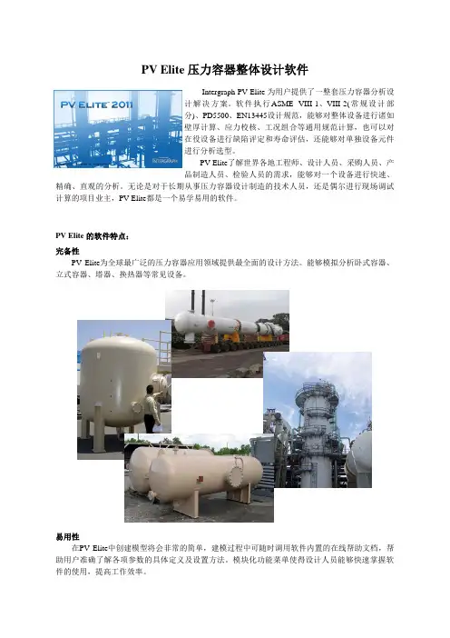
PV Elite 压力容器整体设计软件Intergraph PV Elite 为用户提供了一整套压力容器分析设计解决方案。
软件执行ASME VIII-1、VIII-2(常规设计部分)、PD5500、EN13445设计规范,能够对整体设备进行诸如壁厚计算、应力校核、工况组合等通用规范计算,也可以对在役设备进行缺陷评定和寿命评估,还能够对单独设备元件进行分析选型。
PV Elite了解世界各地工程师、设计人员、采购人员、产品制造人员、检验人员的需求,能够对一个设备进行快速、精确、直观的分析。
无论是对于长期从事压力容器设计制造的技术人员,还是偶尔进行现场调试计算的项目业主,PV Elite都是一个易学易用的软件。
PV Elite 的软件特点:完备性PV Elite为全球最广泛的压力容器应用领域提供最全面的设计方法。
能够模拟分析卧式容器、立式容器、塔器、换热器等常见设备。
易用性在PV Elite中创建模型将会非常的简单,建模过程中可随时调用软件内置的在线帮助文档,帮助用户准确了解各项参数的具体定义及设置方法。
模块化功能菜单使得设计人员能够快速掌握软件的使用,提高工作效率。
准确性PV Elite的三维图形显示功能确保了模型的准确性。
实时交互的分析计算功能指引您进一步找到最终结果。
全球性作为一款全球畅销的软件,PV Elite能够支持ASMEVIII-1、VIII-2(常规设计部分)、PD5500、EN13445等主流压力容器设计规范。
可靠性PV Elite经过全球众多用户多年的使用及定期的更新和升级,已经证明了软件的可靠性。
此外,PV Elite还通过了ASME质量认证(QA)考题测试,计算结果与标准答案相差无几。
周期性PV Elite每年都会按照压力容器设计规范和标准的最新规则进行更新,并提供成熟的设计分析技术。
使用PV Elite能够让您始终站在世界压力容器设计制造技术的最前沿。
软件功能PVelite基于人们熟悉的Windows界面,设计了各种便捷的工具栏和对话框,另外,PVelite的用户自定义功能还允许用户按照自己的工作习惯对功能键进行布局。
压力容器的强度计算压力容器是一种主要用于储存或输送气体、液体等在内部产生较高压力的装置。
它广泛应用于化工、石油、煤炭、电力、冶金等行业中。
为了确保压力容器的安全运行,需要对压力容器的强度进行计算。
1.壁厚计算:压力容器壁厚的计算是压力容器强度计算的基础。
壁厚设计应满足以下条件:①确保容器在内部压力作用下不会破裂;②具有足够的刚度以保证容器的稳定性;③合理分配应力,避免过度集中应力。
壁厚计算可采用多种方法,如薄壁理论、弹性理论、塑性理论等。
其基本原理是根据容器内部压力、容器几何形状、容器材料的力学性能等参数,计算容器受到的应力,并根据相应的材料强度参数确定壁厚。
2.焊缝强度计算:焊接是制造压力容器常用的连接方法之一、焊接连接的强度计算主要涉及焊缝的强度计算和热影响区的强度计算。
焊缝的强度计算包括焊缝的有效截面计算和焊缝应力计算。
焊缝的有效截面计算可采用T型焊缝强度的判定公式,根据焊缝的几何尺寸确定其有效截面积。
焊缝应力计算可采用焊缝剖面应力法或其他适用的方法,根据应力计算公式计算焊缝的应力。
热影响区的强度计算涉及焊缝附近材料的力学性能变化分析。
焊接过程中,受到焊接热源的加热作用,原有材料的晶体结构和性能会发生改变。
根据焊缝热影响区的材料力学性能参数,进行强度计算。
3.耐久性计算:压力容器的耐久性计算主要是考虑容器的疲劳寿命。
在容器内部压力交替作用下,会导致材料发生疲劳损伤。
耐久性计算主要涉及应力幅计算和疲劳寿命计算。
应力幅计算是根据容器的工作条件、材料疲劳强度参数等,计算容器内部压力作用下的应力幅度。
疲劳寿命计算是根据材料的疲劳性能参数,计算容器的疲劳寿命。
总之,压力容器的强度计算是确保容器安全运行的重要环节。
通过合理计算容器的壁厚、焊缝强度和耐久性,能够保证容器在内部压力作用下不会发生破裂和泄漏,从而确保生产过程的安全。
压力容器的强度计算精选文档TTMS system office room 【TTMS16H-TTMS2A-TTMS8Q8-第11章压力容器的强度计算本章重点要讲解内容:(1)理解内压容器设计时主要设计参数(容器内径、设计压力、设计温度、许用应力、焊缝系数等)的意义及其确定原则;(2)掌握五种厚度(计算壁厚、设计壁厚、名义壁厚、有效壁厚、最小壁厚)的概念、相互关系以及计算方法;能熟练地确定腐蚀裕度和钢板负偏差;(3)掌握内压圆筒的厚度设计;(4)掌握椭圆封头、锥形封头、半球形封头以及平板封头厚度的计算。
(5)熟悉内压容器强度校核的思路和过程。
第一节设计参数的确定1、我国压力容器标准与适用范围我国现执行GB150-98 “钢制压力容器”国家标准。
该标准为规则设计,采用弹性失效准则和稳定失效准则,应用解析法进行应力计算,比较简便。
JB4732-1995《钢制压力容器—分析设计标准》,其允许采用高的设计强度,相同设计条件下,厚度可以相应地减少,重量减轻。
其采用塑性失效准则、失稳失效准则和疲劳失效准则,计算比较复杂,和美国的ASME标准思路相似。
2、容器直径(diameter of vessel)考虑压制封头胎具的规格及标准件配套选用的需要,容器筒体和封头的直径都有规定。
对于用钢板卷制的筒体,以内径作为其公称直径。
表1 压力容器的公称直径(mm)如果筒体是使用无缝钢管直接截取的,规定使用钢管的外径作为筒体的公称直径。
表2 无缝钢管制作筒体时容器的公称直径(mm)3、设计压力(design pressure)(1)相关的基本概念(除了特殊注明的,压力均指表压力)✧工作压力P W:在正常的工作情况下,容器顶部可能达到的最高压力。
①由于最大工作压力是容器顶部的压力,所以对于塔类直立容器,直立进行水压试验的压力和卧置时不同;②工作压力是根据工艺条件决定的,容器顶部的压力和底部可能不同,许多塔器顶部的压力并不是其实际最高工作压力(the maximum allowableworking pressure)。
第11章压力容器的强度计算本章重点要讲解内容:(1)理解内压容器设计时主要设计参数(容器内径、设计压力、设计温度、许用应力、焊缝系数等)的意义及其确定原则;(2)掌握五种厚度(计算壁厚、设计壁厚、名义壁厚、有效壁厚、最小壁厚)的概念、相互关系以及计算方法;能熟练地确定腐蚀裕度和钢板负偏差;(3)掌握内压圆筒的厚度设计;(4)掌握椭圆封头、锥形封头、半球形封头以及平板封头厚度的计算。
(5)熟悉内压容器强度校核的思路和过程。
第一节设计参数的确定1、我国压力容器标准与适用范围我国现执行GB150-98 “钢制压力容器”国家标准。
该标准为规则设计,采用弹性失效准则和稳定失效准则,应用解析法进行应力计算,比较简便。
JB4732-1995《钢制压力容器—分析设计标准》,其允许采用高的设计强度,相同设计条件下,厚度可以相应地减少,重量减轻。
其采用塑性失效准则、失稳失效准则和疲劳失效准则,计算比较复杂,和美国的ASME标准思路相似。
2、容器直径(diameter of vessel)考虑压制封头胎具的规格及标准件配套选用的需要,容器筒体和封头的直径都有规定。
对于用钢板卷制的筒体,以内径作为其公称直径。
表1 压力容器的公称直径(mm)如果筒体是使用无缝钢管直接截取的,规定使用钢管的外径作为筒体的公称直径。
表2 无缝钢管制作筒体时容器的公称直径(mm)3、设计压力(design pressure)(1)相关的基本概念(除了特殊注明的,压力均指表压力)✧工作压力P W:在正常的工作情况下,容器顶部可能达到的最高压力。
①由于最大工作压力是容器顶部的压力,所以对于塔类直立容器,直立进行水压试验的压力和卧置时不同;②工作压力是根据工艺条件决定的,容器顶部的压力和底部可能不同,许多塔器顶部的压力并不是其实际最高工作压力(the maximum allowable working pressure)。
③标准中的最大工作压力,最高工作压力和工作压力概念相同。
Table of ContentsCover Sheet (3)Title Page (4)Warnings and Errors: (5)Input Echo: (6)XY Coordinate Calculations: (11)Jacket/VB Calcs: Jacket (12)Internal Pressure Calculations: (16)External Pressure Calculations: (20)Element and Detail Weights: (25)Nozzle Flange MAWP: (28)Natural Frequency Calculation: (29)Wind Load Calculation: (30)Earthquake Load Calculation: (33)Wind/Earthquake Shear, Bending: (34)Wind Deflection: (35)Longitudinal Stress Constants: (36)Longitudinal Allowable Stresses: (37)Longitudinal Stresses due to: (38)Stress due to Combined Loads: (40)Center of Gravity Calculation: (44)Sup. Lug Calcs: Ope: (45)Nozzle Summary: (48)Nozzle Calcs.: N1 (49)Nozzle Calcs.: N2 (54)Nozzle Calcs.: N3 (59)Nozzle Calcs.: N4 (64)Nozzle Calcs.: N5 (69)Nozzle Calcs.: N6 (75)Nozzle Schedule: (80)MDMT Summary: (81)Vessel Design Summary: (83)Cover Page 3DESIGN CALCULATIONIn Accordance with ASME Section VIII Division 1ASME Code Version : 2017Analysis Performed by : ZISHAN ENGINEERS (PVT.) LTD.Job File : C:\USERS\PUBLIC\DOCUMENTS\INTERGRAPH CAS\PVELITEDate of Analysis : May 31,2019 1:51pmPV Elite 2018 SP1, February 2018Title Page 4 Note:PV Elite performs all calculations internally in Imperial Unitsto remain compliant with the ASME Code and any built in assumptionsin the ASME Code formulas. The finalized results are reflected to showthe user's set of selected units.5 PV Elite 2018 SP1 Licensee: ZISHAN ENGINEERS (PVT.) LTD.FileName : JacketModelWarnings and Errors: Step: 0 1:51pm May 31,2019Class From To : Basic Element Checks.==========================================================================Class From To: Check of Additional Element Data==========================================================================There were no geometry errors or warnings.Note: Lug supports should be modeled on an element of their ownwhose length is just slightly greater than the height of the lugassembly. The vessel does not have to be constructed with this extraelement, just modeled this way. This is to insure there is propermass distribution for these types of models.Warning:This is a vertical vessel on support lugs and the earthquake type selectedis a building code. Building codes assume all of the mass is located abovethe point of support. This makes their use on lug supported vesselsquestionable. It is strongly suggested that based on the seismic zoneand applicable parameters, an appropriate lateral (Gx) and (+-) vertical(Gy) acceleration be applied using the G loading option.PV Elite is a trademark of Intergraph CADWorx & Analysis Solutions, Inc. 2018。
第11章压力容器的强度计算本章重点要讲解内容:(1)理解内压容器设计时主要设计参数(容器内径、设计压力、设计温度、许用应力、焊缝系数等)的意义及其确定原则;(2)掌握五种厚度(计算壁厚、设计壁厚、名义壁厚、有效壁厚、最小壁厚)的概念、相互关系以及计算方法;能熟练地确定腐蚀裕度和钢板负偏差;(3)掌握内压圆筒的厚度设计;(4)掌握椭圆封头、锥形封头、半球形封头以及平板封头厚度的计算。
(5)熟悉内压容器强度校核的思路和过程。
第一节设计参数的确定1、我国压力容器标准与适用范围我国现执行GB150-98 “钢制压力容器”国家标准。
该标准为规则设计,采用弹性失效准则和稳定失效准则,应用解析法进行应力计算,比较简便。
JB4732-1995《钢制压力容器—分析设计标准》,其允许采用高的设计强度,相同设计条件下,厚度可以相应地减少,重量减轻。
其采用塑性失效准则、失稳失效准则和疲劳失效准则,计算比较复杂,和美国的ASME标准思路相似。
2、容器直径(diameter of vessel)考虑压制封头胎具的规格及标准件配套选用的需要,容器筒体和封头的直径都有规定。
对于用钢板卷制的筒体,以内径作为其公称直径。
表1 压力容器的公称直径(mm)如果筒体是使用无缝钢管直接截取的,规定使用钢管的外径作为筒体的公称直径。
表2 无缝钢管制作筒体时容器的公称直径(mm)3、设计压力(design pressure)(1)相关的基本概念(除了特殊注明的,压力均指表压力)✧工作压力P W:在正常的工作情况下,容器顶部可能达到的最高压力。
①由于最大工作压力是容器顶部的压力,所以对于塔类直立容器,直立进行水压试验的压力和卧置时不同;②工作压力是根据工艺条件决定的,容器顶部的压力和底部可能不同,许多塔器顶部的压力并不是其实际最高工作压力(the maximum allowable working pressure)。
③标准中的最大工作压力,最高工作压力和工作压力概念相同。
压力容器的强度计算第11章压力容器的强度计算本章重点要讲解内容:(1)理解内压容器设计时主要设计参数(容器内径、设计压力、设计温度、许用应力、焊缝系数等)的意义及其确定原则;(2)掌握五种厚度(计算壁厚、设计壁厚、名义壁厚、有效壁厚、最小壁厚)的概念、相互关系以及计算方法;能熟练地确定腐蚀裕度和钢板负偏差;(3)掌握内压圆筒的厚度设计;(4)掌握椭圆封头、锥形封头、半球形封头以及平板封头厚度的计算。
(5)熟悉内压容器强度校核的思路和过程。
第一节设计参数的确定1、我国压力容器标准与适用范围我国现执行GB150-98“钢制压力容器”国家标准。
该标准为规则设计,采用弹性失效准则和稳定失效准则,应用解析法进行应力计算,比较简便。
JB4732-1995《钢制压力容器—分析设计标准》,其允许采用高的设计强度,相同设计条件下,厚度可以相应地减少,重量减轻。
其采用塑性失效准则、失稳失效准则和疲劳失效准则,计算比较复杂,和美国的ASME标准思路相似。
2、容器直径(diameterofvessel)考虑压制封头胎具的规格及标准件配套选用的需要,容器筒体和封头的直径都有规定。
对于用钢板卷制的筒体,以内径作为其公称直径。
表1压力容器的公称直径(mm)如果筒体是使用无缝钢管直接截取的,规定使用钢管的外径作为筒体的公称直径。
表2无缝钢管制作筒体时容器的公称直径(mm)3、设计压力(designpressure)(1)相关的基本概念(除了特殊注明的,压力均指表压力)工作压力PW:在正常的工作情况下,容器顶部可能达到的最高压力。
①由于最大工作压力是容器顶部的压力,所以对于塔类直立容器,直立进行水压试验的压力和卧置时不同;②工作压力是根据工艺条件决定的,容器顶部的压力和底部可能不同,许多塔器顶部的压力并不是其实际最高工作压力(themaximumallowableworkingpressure)。
③标准中的最大工作压力,最高工作压力和工作压力概念相同。
Table of Contents
Cover Sheet (2)
Title Page (3)
Warnings and Errors : (4)
Input Echo : (5)
XY Coordinate Calculations : (11)
Internal Pressure Calculations : (12)
External Pressure Calculations : (18)
Element and Detail Weights : (23)
Nozzle Flange MAWP : (26)
Conical Section : (27)
Center of Gravity Calculation : (29)
Nozzle Calcs. : Noz N1 Fr20 (30)
Nozzle Calcs. : Noz N1 Fr40 (32)
Nozzle Calcs. : Noz N1 Fr50 (34)
Nozzle Schedule : (41)
Nozzle Summary : (42)
MDMT Summary : (43)
Vessel Design Summary : (44)
Problems/Failures Summary : (47)
Cover Page 2
DESIGN CALCULATION
In Accordance with ASME Section VIII Division 1
ASME Code Version : 2010 Edition, 2011a Addenda
Analysis Performed by : ZISHAN ENGINEERS (PVT.) LTD.
Job File : C:\DOCUMENTS AND SETTINGS\ADMINISTRATOR\桌面\UNT
Date of Analysis : Oct 8,2014
PV Elite 2012, January 2012
Title Page 3
Warnings and Errors : Step: 0 2:56p Oct 8,2014
Class From To : Basic Element Checks.
==========================================================================
Warn. 30 40 Inconsistent external pressure definition. The given
external pressure was not the same as the internal pressure on the
following element.
Class From To: Check of Additional Element Data
==========================================================================
Warn 30 40 Check UG-32(j) and UG-81 for Crown Radius > OD
PV Elite is a trademark of Intergraph CADWorx & Analysis Solutions, Inc. 2012
Input Echo : Step: 1 2:56p Oct 8,2014 PV Elite Vessel Analysis Program: Input Data
Design Internal Pressure (for Hydrotest) 100.00 psig
Design Internal Temperature 200 F
Type of Hydrotest not Specified
Hydrotest Position Horizontal
Projection of Nozzle from Vessel Top 0.0000 in.
Projection of Nozzle from Vessel Bottom 0.0000 in.
Minimum Design Metal Temperature -20 F
Type of Construction Welded
Special Service None
Degree of Radiography RT 1
Miscellaneous Weight Percent 0.0
Use Higher Longitudinal Stresses (Flag) Y
Select t for Internal Pressure (Flag) N
Select t for External Pressure (Flag) N
Select t for Axial Stress (Flag) N
Select Location for Stiff. Rings (Flag) N
Consider Vortex Shedding Y
Perform a Corroded Hydrotest N
Is this a Heat Exchanger No
User Defined Hydro. Press. (Used if > 0) 0.0000 psig
User defined MAWP 0.0000 psig
User defined MAPnc 0.0000 psig
Load Case 1 NP+EW+WI+FW+BW
Load Case 2 NP+EW+EE+FS+BS
Load Case 3 NP+OW+WI+FW+BW
Load Case 4 NP+OW+EQ+FS+BS
Load Case 5 NP+HW+HI
Load Case 6 NP+HW+HE
Load Case 7 IP+OW+WI+FW+BW
Load Case 8 IP+OW+EQ+FS+BS
Load Case 9 EP+OW+WI+FW+BW
Load Case 10 EP+OW+EQ+FS+BS
Load Case 11 HP+HW+HI
Load Case 12 HP+HW+HE
Load Case 13 IP+WE+EW
Load Case 14 IP+WF+CW
Load Case 15 IP+VO+OW
Load Case 16 IP+VE+EW
Load Case 17 NP+VO+OW
Load Case 18 FS+BS+IP+OW
Load Case 19 FS+BS+EP+OW。