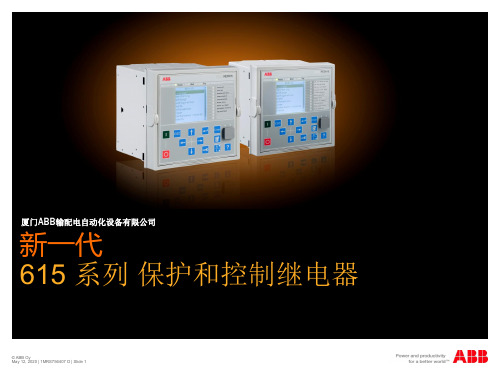
RED615线路差动保护继电器
- 格式:pdf
- 大小:1.16 MB
- 文档页数:2

继电保护装置RED670二次回路增加控制回路断线功能作者:张法胜来源:《电气传动自动化》2019年第05期摘要:通过研究ABB公司RED670线路差动保护装置,发现该装置不具备控制回路断线监视等功能,该功能实现必须外加元件。
关键词:线变组;保护装置;控制回路断线文章编号:1005-7277(2019)05-0213-02Abstract:Through the research on ABB RED670 line differential protection device, it is found that the device does not have control loop disconnection monitoring and other functions.Key words:Wire is set; Protective device; Control loop disconnected0 引言华北石化公司共有3座110kV变电站,110kV总变电站110kV侧为双母线分段接线,另外2座110kV变电站电源引自总变电站,采用线路变压器组接线。
总变电站110kV侧一次设备为ABB公司GIS设备,线路变压器组保护装置采用ABB公司RED670线路差动保护,保护構成见图1。
RED670集保护、测控于一体,具有保护功能配置灵活、硬件可扩展等特点,由电源模块、模拟量输入模块、开关量输入模块、开关量输出模块、通信模块、时间同步模块等组成。
但通过研究发现,该装置没有国内110kV线路保护装置自带控制回路断线监视功能的插件。
若直接应用,不能构成完整的保护测控装置,不满足国内有关设计规范。
1 控制回路断线问题在电力系统中,断路器是保证正常供电,切除故障的重要设备,为保证断路器可靠动作,通常设置断路器控制回路断线监视回路,监视断路器合、跳闸线圈及断路器控制回路的完好性,并在断路器控制回路断线时报警。
地铁供电故障处理措施探讨摘要:地铁用电量是非常巨大的,作为地铁正常运作的重要支撑部分,其故障发生带来一定的负面影响。
本文主要对A\B地铁线路的交流电故障进行分析,提出解决措施,避免往后此类故障的发生。
关键词:城市轨道;供电系统;交流送电;故障;措施前言地铁采用集中供电模式,环网电缆连接变电所逐所送电,不能越所带电,因此,中间任何一个环节出现故障均会影响到送电进程。
一、地铁各变电所送电流程二、地铁供电故障案例与措施(一)主变电站至正线变电所环网电缆相序(A相、B相电缆接反)错误故障:在B线A站主变电站向B站变电所电缆送电后核相,发现A相、B相电缆接反,当时送电组有人提议继续送电,可将此处的相序按错误的相序记住倒着核,但这将会引起相序混乱,尤其影响电源备投最终导致设备故障或威胁人身安全。
解决方案:暂停送电,做好防护措施,让施工人员倒完相序后再行送电。
此类问题应发现一处,纠正一处。
避免方法:试验人员完成电缆试验,并用油漆笔在电缆头1m外标示相序,安装人员严格按标示对应安装。
(二)电缆屏蔽层未接地故障A线从A站变电所2#馈线柜向B站变电所2#进线电缆送电时,A站35kV开关柜的电缆室听到有嗞嗞的异响,按程序立即分闸,经排查为电缆屏蔽层未接地。
根据《电力工程电缆设计规范》(GB50127-2007),第4.1.19条电力电缆金属护层必须直接接地。
4.1.11条规定交流系统单芯电力电缆金属层接地方式的选择,应符合下列规定:1线路不长,且能满足本规范第4.1.10条要求时,应采取在线路一端或中央部位单点直接接地。
2线路较长,单点直接接地方式无法满足本规范第4.1.10条要求时,水下电缆、35kV及以下电缆或输送容量较小的35kV及以上电缆,可采取在线路两端直接接地。
此次事故是因施工人员疏忽未按设计要求造成该端电缆屏蔽层未接地而引起的。
解决方案:做好停电作业防护措施,对电缆放电后,将该电缆屏蔽层做接地。
避免方法:除施工按设计要求规范作业外,还应加强复查、验收。
馈线保护测控装置REF615产品指南目 录1概述...............................................................12标准配置........................................................13保护功能........................................................34应用...............................................................75控制功能......................................................106测量.............................................................107故障录波......................................................108事件记录......................................................109故障数据记录...............................................1010断路器监视..................................................1011跳闸回路监视...............................................1112自检功能......................................................1113VT熔丝断线监视..........................................1114电流回路监视.. (1115)访问控制 (11)16输入和输出装置...........................................1217通信.............................................................1318技术数据......................................................1419显示选项......................................................3620安装方法......................................................3721外壳和插件单元...........................................3722选机及订货号...............................................3823配件及其订货号...........................................4224工具.............................................................4225ABB采用的解决方案....................................4426接线图..........................................................4527认证.............................................................4828参考资料 (4829)功能、代码和符号 (49)免责声明本文信息可能会更改,恕不另行通知。
馈线保护继电器REF615用户指南目 录1概述...................................42标准配置...............................43保护功能...............................54应用...................................75控制功能...............................96测量功能...............................97故障录波...............................98事件记录...............................99故障数据记录...........................910断路器监视.............................911跳闸回路监视..........................1012自检功能 (1013)访问控制 (10)14输入和输出............................1015通信..................................1116技术数据..............................1217显示选项..............................2818安装方法..............................2919继电器外壳和继电器插件单元............2920整机订货号............................3021配件订货号............................3322工具..................................3323端子图................................3524认证..................................3725参考资料 (3726)功能、代码和符号 (38)免责声明本文件中的信息可能会更改,恕不另行通知。
ABB馈线保护测控装置REF615集保护、控制、测量、通信、监视和弧光保护功能于一体,完全根据国际标准IEC 61850平台研发和设计,从而使产品从根本上支持站内智能设备的互操作与水平通信等特性。
馈线保护测控装置REF615全新615系列配置灵活 应用广泛REF615可作为配电网中架空线和馈线的主保护,也可作为变压器等设备的后备保护。
主要用于电力变电站、电厂等电力行业以及水泥、冶金、石化、汽车、半导体、造纸、烟草等工业用户,也可用于市政、机场、港口、房地产等行业。
为满足用户需要,REF615可以提供7种标准配置的应用。
保护逻辑和相关功能均针对中国市场需求进行了特别优化。
保护控制功能齐全 集成弧光保护REF615提供带方向或无方向过流和接地故障保护,同时也支持过压、低电压、零序电压保护、热过负荷保护、灵敏接地保护及速断接地保护(包括间歇性接地保护)。
此外,该装置还集成了灵活配置的多轮次重合闸功能,可实现重合闸前、后加速和手合加速功能。
REF615加装可选配件,还可直接集成三个弧光保护通道。
用户无需另外购置和安装弧光保护装置即可实现对开关柜断路器、电缆和母线室的弧光检测和快速保护。
REF615支持当地和远方控制功能。
用户通过装置面板上的控制按钮或者后台监控系统(SCADA)即可实现对断路器的分、合闸操作。
为防止未授权用户误操作并保证用户按照相应权限操作,该装置定义了四个级别的操作权限:浏览者、操作员、工程师和管理员。
不同级别用户使用不同的账号和密码登陆。
这些权限设置适用于各种访问方式,包括装置面板操作,web访问及使用PCM600装置配置工具。
基于IEC 61850设计 支持水平通信REF615支持IEC 61850规约从而真正实现站内智能设备间的相互5-103。
REF615按照IEC 61850 规约设计,包括与后台监控系统的通信和保护装置之间的GOOSE水平通信并符合IEC 61850-8-1的各项规范。
Line differential protection and control RED615Compact and versatile solution for utility and industrial power distribution systemsRelion ®615 seriesIdeal selectivity for two-end line differential protectionRED615 is a phase-segregated, two-end line differential protection and control relay for protection, control, measurement and supervision in utility and industrial power distribution systems, including radial, looped and meshed distribution networks, with or without distributed power generation. RED615 is also ideal for line differential applications with an in-zone transformer. RED615 relays communicate between substations either over a fiber-optic link or a galvanic pilot wire connection.ApplicationRED615 has been designed to be the main protectionfor overhead line and cable feeders, in either isolated neutral, resistance-earthed, compensated or effectively earthed distribution networks, depending on the standard configuration.RED615 is available in five standard configurations, one of which is a plain line differential protection with overcurrent backup protection two with added earth-fault protection functionality in particular, and another two further extended with directional overcurrent as well as phase-voltage and frequency-based protection. Switch on to fault is now introduced in all standard configurations and voltage unbalance in the two extended ones. They both also include a fault locator which locates short circuits in radial distribution networks and earth faults in effectively and low-resistance earthed ones. If the fault current is as high as or higher than the load current, earth faults in isolated neutral distribution networks will also be located. In addition, one of the two extended standard configurations includes support for three combi-sensor inputs for phase currents (Rogowski coil)and voltages (voltage divider), whereas the other supports conventional current and voltage instrument transformers as the rest of the standard configurations.Two RED615 relays interconnected over a communication link form an entirely selective unit protection scheme. Protection of ring-type and meshed distribution networks generally requires unit protection solutions, also applied in radial networks containing distributed power generation.The standard configurations can be tailored to meet application-specific requirements using the IEC 61850-compliant Protection and Control IED Manager PCM600. Human-machine interfaceAs a member of the Relion® product family, RED615 shares the same human-machine interface (HMI) look and feel as the other Relion protection and control relays and IEDs. The same look and feel includes the location of a push button with a certain function and the menu structure.RED615 is equipped with a large graphical display whichcan show customizable single-line diagrams (SLD) with position indication for the circuit breaker, disconnectors and the earthing switch. Also measured values provided by the chosen standard configuration can be displayed. The SLDs are customized using PCM600 and can have multiple pages for easy access to selected information. The SLDs can be accessed not only locally but also via the web browser-based HMI that has now been enriched with a number of usability enhancing features.Standardized communicationRED615 fully supports the IEC 61850 standard for communication and interoperability of substation automation devices, including fast GOOSE messaging and now alsoIEC 61850-9-2 LE and Edition 2, offering substantial benefits in terms of extended interoperability. The line differential relay further supports the DNP3, IEC 60870-5-103 and Modbus®protocols, now introducing also the parallel redundancy protocol (PRP) and the high-availability seamless redundancy (HSR) protocol. With the protocol adapter SPA-ZC 302, Profibus DVP1 can also be used. RED615 is able to use two communication protocols simultaneously.For redundant Ethernet communication, RED615 offers two optical Ethernet network interfaces. The redundant Ethernet solution can be built on the Ethernet-based IEC 61850, Modbus® and DNP3 protocols.The implementation of the IEC 61850 standard in RED615 covers both vertical and horizontal communication, including GOOSE messaging with both binary and analog signalsas well as parameter setting according to IEC 61850-8-1.In addition, IEC 61850-9-2 LE process bus with sending sampled values of both analog voltages and currents and receiving sampled values of voltages is introduced. The sampled values can also be used for synchro-check, bothin conventional instrument transformer and sensor-based applications, to ensure safe interconnection of two networks. For process bus applications, which require high-accuracy time synchronization, IEEE 1588 V2 is used, with a time stamp resolution of not more than four microseconds.IEEE 1588 V2 is supported in all variants with a redundant Ethernet communication module. In addition, RED615 supports synchronization over Ethernet using SNTP or over a separate bus using IRIG-B.Main benefits−Withdrawable plug-in unit design for swift installation and testing−Selective unit protection as phase-segregated two-end line differential protection, either with sensors or conventional2 Line-differential protection and control | RED615Protection function overview of the E configuration of RED615.instrument transformers−Ready-made standard configurations, including line differ-ential communication, for fast and easy setup with tailoring capabilities−Line differential communication between substations either over a fiber-optic link or a galvanic pilot wire connection−Ideal for line differential applications with an in-zone trans-former−IEC 61850 Edition 2 and Edition 1 support, including HSR and PRP, GOOSE messaging and IEC 61850-9-2 LE for less wiring and supervised communication−IEEE 1588 V2 for high-accuracy time synchronization and maximum benefit of substation-level Ethernet communica-tion−Large graphical display for showing customizable SLDs, accessible either locally or through a web browser-based HMI 615 seriesRED615 is a member of ABB’s Relion product family and part of its 615 protection and control series of relays, characterized by compactness and withdrawable plug-in unit design. In addition to RED615, the 615 series includes the following relays:−REF615 Feeder protection and control−RET615 Transformer protection and control−REU615 Voltage protection and control−REM615 Motor protection and control−REV615 Capacitor bank protection and controlLife cycle servicesLife cycle services ABB offers full support for all protection and control relays throughout their entire lifecycle. Our extensive life cycle services include training, customer support, maintenance and modernization.RED615 | Line-differential protection and control 34 Line-differential protection and control | RED615Supported functions, codes and symbols Functionality ProtectionThree-phase non-directional overcurrent protection, low stage Three-phase non-directional overcurrent protection, high stageThree-phase non-directional overcurrent protection, instantaneous stage Three-phase directional overcurrent protection, low stage Three-phase directional overcurrent protection, high stage Non-directional earth-fault protection, low stage Non-directional earth-fault protection, high stageNon-directional earth-fault protection, instantaneous stage Directional earth-fault protection, low stage Directional earth-fault protection, high stage Admittance based earth-fault protection Wattmetric based earth-fault protection Transient / intermittent earth-fault protection Harmonics based earth-fault protectionNon-directional (cross-country) earth fault protection, using calculated Io Negative-sequence overcurrent protection Phase discontinuity protection Residual overvoltage protection Three-phase undervoltage protection Three-phase overvoltage protection Positive-sequence undervoltage protection Negative-sequence overvoltage protection Frequency protectionThree-phase thermal protection for feeders, cables and distribution transformers Three-phase thermal overload protection for power transformers, two time constants Binary signal transferCircuit breaker failure protection Three-phase inrush detector Switch onto fault Master tripMulti-purpose protection Fault locatorLine differential protection with in zone power transformer High impedance fault detectionStandard configurations DescriptionLine differential protectionLine differential protection with directional earth-fault protection and circuit breaker condition monitoring Line differential protection with non-directional earth-fault protection and circuit breaker condition monitoring Line differential protection with directional overcurrent and earth-fault protection, voltage and frequency based protection and measurements, synchro-check and circuit-breaker condition monitoring (RTD option, optional power quality and fault locator)Line differential protection with directional overcurrent and earth-fault protection, voltage and frequency based protection and measurements, circuit-breaker condition monitoring (sensor inputs, optional power quality, fault locator and synchro-check with IEC 61850-9-2LE)Standard configurationA B CD E Standard configurationsRED615 | Line-differential protection and control 5B 121-----21)1 1)(3) 1) 3)(3) 1) 3)1 4)(1) 3) 4) 1213 1)- - --- 111111218 -11E - -121 - - -2 2)1 2)(3) 2) 3)(3) 2) 3)1 2) 4)(1) 3) 4) 1213 2)33114111111218(1)1-A 121-----------2---------11 5)11218-11D - - 121-- - 21(3) 3)(3) 3)1 4)(1) 3) 4) 121333114111111218(1)11IEC-ANSI 51P-151P-250P/51P 67-167-251N-151N-2 50N/51N 67N-167N-221YN 32N 67NIEF 51NHA 51N-24646PD 59G 275947U+47O-8149F 49T/G/C BST51BF/51NBF 68SOTF 94/86MAP 21FL 87L HIZC 121--211-----(1) 3) 4) -21- -- -- - 111111218 -11IEC 606173I>3I>> 3I>>>3I> ->3I>> -> Io>Io>> Io>>>Io> ->Io>> ->Yo> ->Po> ->Io> -> IEF Io>HA Io>>I2>I2/I1>Uo>3U<3U>U1<U2>f>/f<,df/dt 3Ith>F 3Ith>T/G/C BST 3I>/Io>BF 3I2f>SOTF Master Trip MAP FLOC 3Id/I>HIFIEC 61850PHLPTOC PHHPTOC PHIPTOC DPHLPDOC DPHHPDOC EFLPTOC EFHPTOC EFIPTOC DEFLPDEF DEFHPDEF EFPADM WPWDE INTRPTEF HAEFPTOC EFHPTOC NSPTOC PDNSPTOC ROVPTOV PHPTUV PHPTOV PSPTUV NSPTOV FRPFRQ T1PTTR T2PTTR BSTGGIO CCBRBRF INRPHAR CBPSOF TRPPTRC MAPGAPC SCEFRFLO LNPLDF PHIZ1, 2,... = number of included instances / I/Os( ) = optionalSupported functions, codes and symbolsFunctionalityPower QualityCurrent total demand distortionVoltage total harmonic distortionVoltage variationVoltage unbalanceControlCircuit-breaker controlDisconnector controlEarthing switch controlDisconnector position indicationEarthing switch indicationAuto-reclosingSynchronism and energizing checkCondition MonitoringCircuit-breaker condition monitoringTrip circuit supervisionCurrent circuit supervisionFuse failure supervisionProtection communication supervisionRuntime counter for machines and devicesMeasurementDisturbance recorderLoad profile recordFault recordThree-phase current measurementSequence current measurementResidual current measurementThree-phase voltage measurementResidual voltage measurementSequence voltage measurementThree-phase power and energy measurementRTD/mA measurementFrequency measurementIEC 61850-9-2 LE sampled value sending 7) 8)IEC 61850-9-2 LE sampled value receiving (voltage sharing) 7) 8) 6 Line-differential protection and control | RED615RED615 | Line-differential protection and control 7B ----12132(1)121-11111111-1------D (1) 6)(1) 6)(1) 6)(1) 6)12132(1)11211111111112111(1)1(1)(1)A ----12132--21-1111111---------IEC 61850CMHAI VMHAI PHQVVR VSQVUB CBXCBR DCXSWI ESXSWI DCSXSWI ESSXSWI DARREC SECRSYN SSCBR TCSSCBR CCRDIF SEQRFUF PCSRTPC MDSOPT RDRE LDPMSTA FLTRFRC CMMXU CSMSQI RESCMMXU VMMXU RESVMMXU VSMSQI PEMMXU XRGGIO130FMMXU SMVSENDER SMVRCVIEC-ANSI PQM3I PQM3V PQMV PQMUBV I ↔ O CB I ↔ O DCC I ↔ O ESC I ↔ O DC I ↔ O ES 7925CBCM TCM MCS 3I 60PCS OPTM DFR LOADPROF FAULTREC 3I I1, I2, I0In 3V Vn V1, V2, V0P , E X130 (RTD)fSMVSENDER SMVRCVIEC 60617PQM3I PQM3U PQMU PQMUBU I ↔ O CB I ↔ O DCC I ↔ O ESC I ↔ O DC I ↔ O ES O → I SYNC CBCM TCS MCS 3I FUSEF PCS OPTS DR LOADPROF FAULTREC 3I I1, I2, I0Io 3U Uo U1, U2, U0P , E X130 (RTD)fSMVSENDER SMVRCVC ----12132(1)121-11111111--------E (1) 6)(1) 6)(1) 6)(1) 6)12132(1)(1) 7)1211111111211 (2) 7)-11-1(1)(1)1) “Uo measured” is always used.2)“Uo calculated” is always used.3)One of the following can be ordered as an option: admittance-based E/F, wattmetric-based E/F or harmonics-based E/F.4)“Io measured” is always used.5)“Io calculated” is always used.6)Power quality option includes current total demand distortion, voltage total harmonic distortion, voltage variation and voltage unbalance.7)Available only with IEC 61850-9-28)Available only with COM0031-00371, 2,... = number of included instances / I/Os( ) = optionalContact us1M R S 756489 H , 5.0 F P 1 © C o p y r i g h t 2015 A B B . A l l r i g h t s r e s e r v e d .For more information, please refer to RED615 Product Guide, or contact us:ABB Oy, Medium Voltage Products Distribution Automation P .O. Box 699FI-65101 VAASA, Finland Phone: +358 10 22 11Fax: +358 10 22 41094ABB India Limited, Distribution Automation Maneja WorksVadodara – 390013, India Phone: +91 265 272 4402Fax: +91 265 263 8922/mediumvoltage/substationautomation。