霍尼韦尔6500说明书
- 格式:pdf
- 大小:112.61 KB
- 文档页数:1

6500/6100English 6简体中文 18繁體中文 356EnglishImportantRead this user manual carefully before you use theappliance and save it for future reference.Danger-Keep the charger away from water. Do not place orstore it over or near water contained in a bathtub,washbasin, sink etc. Do not immerse the charger inwater or any other liquid. After cleaning, make surethe charger is completely dry before you connect it tothe wall socket.Warning-The mains cord cannot be replaced. If the mains cordis damaged, discard the charger.-Always have the charger replaced with one of theoriginal type in order to avoid a hazard.-Do not use the charger outdoors or near heatedsurfaces.-If the appliance is damaged in any way (brush head,toothbrush handle or charger), stop using it. Thisappliance contains no serviceable parts. If theappliance is damaged, contact the Consumer CareCenter in your country (see chapter 'Warranty andsupport').-This appliance can be used by children and personswith reduced physical, sensory or mental capabilitiesor lack of experience and knowledge if they havebeen given supervision or instruction concerning useof the appliance in a safe way and understand thehazards involved. Cleaning and user maintenanceshall not be made by children without supervision.-Children shall not play with the appliance. Caution-Do not clean the brush head, the handle or thecharger in the dishwasher.-If you have had oral or gum surgery in the previous 2months, consult your dentist before you use thetoothbrush.7English-Consult your dentist if excessive bleeding occurs afterusing this toothbrush or if bleeding continues to occurafter 1 week of use. Also consult your dentist if youexperience discomfort or pain when you use thePhilips Sonicare.-The Philips Sonicare toothbrush complies with thesafety standards for electromagnetic devices. If youhave a pacemaker or other implanted device, contactyour physician or the device manufacturer of theimplanted device prior to use.-If you have medical concerns, consult your doctorbefore you use the Philips Sonicare.-This appliance has only been designed for cleaningteeth, gums and tongue. Do not use it for any otherpurpose. Stop using the appliance and contact yourdoctor if you experience any discomfort or pain.-The Philips Sonicare toothbrush is a personal caredevice and is not intended for use on multiplepatients in a dental practice or institution.-Stop using a brush head with crushed or bent bristles.Replace the brush head every 3 months or sooner ifsigns of wear appear. Do not use other brush headsthan the ones recommended by the manufacturer.-If your toothpaste contains peroxide, baking soda orbicarbonate (common in whitening toothpastes),thoroughly clean the brush head with soap and waterafter each use. This prevents possible cracking of theplastic.Electromagnetic fields (EMF)This Philips appliance complies with all applicablestandards and regulations regarding exposure toelectromagnetic fields.Radio Equipment Directive-Radio Equipment in this product operates at 13.56MHz-Maximum RF power transmitted by the RadioEquipment is 30.16dBm8EnglishIntroductionCongratulations on your purchase and welcome toPhilips! To fully benefit from the support that Philipsoffers, register your product at/welcome.Your Philips Sonicare (Fig. 1)1Hygienic travel cap2Smart brush head(s)*3Handle4Power on/off button5Intensity light6Mode/intensity button7Mode light8Brush head replacement reminder light9Battery indication10Charging base11Travel case (specific types only)**Note: The content of the box may vary based on themodel purchased.Brush headsYour Philips Sonicare comes with one or more brushheads which are designed to deliver superior results foryour oral care needs.Philips Sonicare BrushSync TechnologyYour brush head(s) are enabled with BrushSynctechnology. This technology enables 2 features with thistoothbrush:1Brush head mode pairing (see 'Features andAccessories')2Brush head replacement reminder (see 'Features andAccessories')This symbol indicates the brush head is equipped withBrushSync technology. (Fig. )Brushing modesYour power toothbrush is equipped with 3 differentmodes to accommodate all your oral care needs.9EnglishTo change modes, press the mode/intensity button whilethe toothbrush is off.The following modes are available:Clean modeClean is a 2-minute mode, recommended to be used withintensity level 3. It gives you a thorough and completeclean and is recommended to be used with the C2Optimal Plaque Control brush head.White modeWhite is a 2-minute 30-seconds mode, recommended tobe used with intensity level 3 and the W2 Optimal Whitebrush head.Gum Care modeGum Care is a 3-minute mode, recommended to be usedwith intensity level 3 and the G2 Optimal Gum Care brushhead.Intensity settingsYour power toothbrush gives you the option to choosebetween 3 different intensity levels: low, medium andhigh. (Fig. ) Based on the brush head you attach, theintensity will be selected. The intensity can be changed bypressing the mode/intensity button while brushing. Foroptimal results it is recommended to use theautomatically selected intensity. The intensity cannot bechanged as long as the handle is powered off or paused. Using your Philips SonicareBrushing instructions1Press the brush head onto the handle in such a waythat the bristles will face the front of the handle. (Fig. )2Firmly press the brush head down onto the metalshaft until it stops.Note: It is normal to see a slight gap between thebrush head and the handle.3Wet the bristles. (Fig. )10English4Apply a small amount of toothpaste on the bristles.(Fig. )5Place the toothbrush bristles against the teeth at aslight angle (45 degrees), pressing firmly to make thebristles reach the gumline or slightly beneath thegumline. (Fig. )Note: A change in vibration (and a slight change insound) alerts you when you apply too much pressurewhile brushing.Note: Keep the center of the brush in contact with theteeth at all times.6Press the power on/off button to turn on the PhilipsSonicare. (Fig. )7Gently keep the bristles placed on the teeth and in thegumline. Brush your teeth with small back and forthmotion so the bristles reach between the teeth. (Fig. )Note: The bristles should slightly flare. Do not scrub.8To clean the inside surfaces of the front teeth, tilt thebrush handle semi-upright and make several verticaloverlapping brushing strokes on each tooth. (Fig. )9To make sure you brush evenly throughout themouth, divide the mouth into 4 sections using theQuadpacer feature. (Fig. ) The quadpacer featurebeeps after 30 seconds.10Brush for the full 2 minutes following the Quadpacer.(Fig. ) After 2 minutes, the toothbrush willautomatically shut off.In white mode, after 2 minutes the handle willcontinue to brush for 30 seconds so that you canbrighten and polish your front teeth. During theextra time, the Quadpacer beeps every 15 seconds.In gum care mode, after 2 minutes the handle willcontinue to brush for an additional minute so youcan gently stimulate and massage your gums.During the extra time, the Quadpacer beeps every15 seconds.-After you have completed the brushing cycle, you canspend additional time brushing the chewing surfacesof your teeth and areas where staining occurs. (Fig. )11EnglishNote: Your Philips Sonicare toothbrush is safe to useon:- Braces (brush heads wear out sooner when used onbraces)- Dental restorations (fillings, crowns, veneers)Note: When the Philips Sonicare toothbrush is used inclinical studies, it must be used in the Clean mode (forplaque and gum health claims) or in White mode (forwhitening claims) at high intensity with EasyStartturned off.Features-EasyStart-Brush head replacement reminder-Pressure sensor-Brush head mode pairing-QuadpacerEasy-startThis Philips Sonicare model comes with the EasyStartfeature deactivated. The EasyStart feature gentlyincreases the power over the first 14 brushings to helpyou get used to the brushing with the Philips Sonicare.Brush head replacement reminderYour Philips Sonicare is equipped with BrushSynctechnology that tracks the wear of your brush head. (Fig.)1When attaching a new smart brush head for the firsttime the brush head replacement reminder lightblinks green three times. This confirms you have aPhilips brush head with BrushSync technology.12English2Over time, based on the pressure you apply and theamount of time used, the handle will track brush headwear in order to determine the optimal time tochange your brush head. This feature gives you theguarantee for the best cleaning and care of yourteeth.3When the brush head replacement reminder lightPressure sensorYour Philips Sonicare is equipped with an advancedsensor that measures the pressure you apply whilebrushing. If you apply too much pressure, the toothbrushwill provide immediate feedback to indicate that youneed to reduce the pressure. This feedback is given by aBrush head mode pairingAn RFID chip inside the brush head communicates withthe toothbrush handle. When you attach a brush head,the handle automatically recognizes the brush head andselects the right mode and intensity level to optimizeyour brushing performance.QuadpacerThe Quadpacer is an interval timer that has a short beepand pause to remind you to brush the different sectionsof your mouth. Depending on the brushing mode youhave selected (see 'Brushing modes'), the Quadpacerbeeps at different intervals during the brushing cycle. Activating or deactivating featuresYou can activate or deactivate the following features ofyour toothbrush:-EasyStart-Brush head replacement reminder-Pressure sensor13EnglishTo activate or deactivate these features, follow theinstructions below:EasyStart1Put the handle on the plugged-in charger.2Press and hold the power on/off button while thehandle remains on the charger.3Keep the power on/off button pressed until you heara single short beep (after 2 seconds).4Release the power on/off button.-Triple tone of low-med-high means the EasyStartfeature has been activated. The brush headreplacement light and battery light will also blinkgreen 2 times in unison to confirm activation.-Triple tone of high-med-low means the EasyStartfeature has been deactivated. The brush headreplacement light and battery light will also blinkamber 2 times in unison to confirm deactivation.Note: To achieve clinical efficacy, EasyStart needs to bedeactivated.Brush head replacement reminder1Put the handle on the plugged-in charger.2Press and hold the power on/off button while thehandle remains on the charger.3Keep the power on/off button pressed until you heara series of two short beeps (after 4-5 seconds).4Release the power on/off button.-Triple tone of low-med-high means the Brushhead replacement reminder feature has beenactivated. The brush head replacement light andbattery light will also blink green 2 times in unisonto confirm activation.-Triple tone of high-med-low means the Brushhead replacement reminder feature has beendeactivated. The brush head replacement lightand battery light will also blink amber 2 times inunison to confirm deactivation.Pressure sensor1Put the handle on the plugged-in charger.14English2Press and hold the power on/off button while thehandle remains on the charger.3Keep the power on/off button pressed until you heara series of three short beeps (after 6-7 seconds).4Release the power on/off button.-Triple tone of low-med-high means the pressuresensor feature has been activated. The brush headreplacement light and battery light will also blinkgreen 2 times in unison to confirm activation.-Triple tone of high-med-low means the pressuresensor feature has been deactivated. The brushhead replacement light and battery light will alsoblink amber 1 time in unison to confirmdeactivation.If you continue holding the power on/off button afterthe three short beeps, the activate/deactivate sequencerepeats.Battery status and charging1Put the plug of the charger in an electrical outlet.2Place the handle on the charger.-The charger will emit 2 short beeps to confirm thatthe handle is placed properly.-The flashing light of the battery level indicatorshows that the toothbrush is charging.-When handle is fully charged on the charger, thebattery light shows solid green for 30 seconds andswitches off.Note: Your toothbrush comes pre-charged for first use.After first use, charge for at least 24 hours.Battery status (when handle is not on charger)When removing the Philips Sonicare from the charger,the battery light at the bottom of the toothbrush willindicate the status of the battery life.-Solid green LED: full battery-Flashing green LED: medium battery-Flashing amber LED and three beeps: low battery15English-Flashing amber LED and two sets of five beeps: Nobrushing sessions left (charge toothbrush) CleaningNote: Do not clean the brush head, handle or travel casein the dishwasher.Toothbrush handle1Remove the brush head and rinse the metal shaft areawith warm water. Make sure you remove any residualtoothpaste (Fig. ).Note: Do not push on the rubber seal on the metalshaft with sharp objects, as this may cause damage.2Wipe the entire surface of the handle with a dampcloth.Note: Do not use isopropyl rubbing alcohol, vinegar orbleach to clean handle as this may causediscoloration.Brush head1Rinse the brush head and bristles after each use (Fig. ).2Remove the brush head from the handle and rinse thebrush head connection with warm water at least oncea week.Charger1Unplug the charger before you clean it.2Wipe the surface of the charger with a damp cloth.Make sure you remove any toothpaste or otherresidue from the charger surfaces.StorageIf you are not going to use your Philips Sonicare for anextended period of time, unplug the charger from thewall socket, clean it and store it in a cool and dry placeaway from direct sunlight.Locating the model numberLook on the bottom of the Philips Sonicare toothbrushhandle for the model number (HX684x/HX685x).16EnglishRecycling-Do not throw away the product with the normalhousehold waste at the end of its life, but hand it in atan official collection point for recycling. By doing this,you help to preserve the environment.-This product contains a built-in rechargeable batterywhich shall not be disposed of with normal householdwaste. Please take your product to an officialcollection point or a Philips service center to have aprofessional remove the rechargeable battery.-Follow your country’s rules for the separate collectionof electrical and electronic products and rechargeablebatteries. Correct disposal helps prevent negativeconsequences for the environment and humanhealth.Removing the rechargeable batteryWarning: Only remove the rechargeable battery whenyou discard the appliance. Make sure the battery iscompletely empty when you remove it.To remove the rechargeable battery, you need a towel orcloth, a hammer and a flat-head (standard) screwdriver.Observe basic safety precautions when you follow theprocedure outlined below. Be sure to protect your eyes,hands, fingers, and the surface on which you work.1To deplete the rechargeable battery of any charge,remove the handle from the charger, turn on thePhilips Sonicare and let it run until it stops. Repeat thisstep until you can no longer turn on the PhilipsSonicare.2Remove and discard the brush head. Cover the entirehandle with a towel or cloth (Fig. ).3Hold the top of the handle with one hand and strikethe handle housing 0.5 inch above the bottom end.Strike firmly with a hammer on all 4 sides to eject theend cap (Fig. ).Note: You may have to hit on the end several times tobreak the internal snap connections.4Remove the end cap from the toothbrush handle. Ifthe end cap does not release easily from the housing,repeat step 3 until the end cap is released (Fig. ).17English5Holding the handle upside down, press the shaftdown on a hard surface. If the internal componentsdo not easily release from the housing, repeat step 3until the internal components are released (Fig. ).6Remove the rubber battery cover.7Wedge the screwdriver between the battery and theblack frame at the bottom of the internalcomponents. Then pry the screwdriver away from thebattery to break the bottom of the black frame (Fig. ).8Insert the screwdriver between the bottom of thebattery and the black frame to break the metal tabconnecting the battery to the green printed circuitboard. This will release the bottom end of the batteryfrom the frame (Fig. ).9Grab the battery and pull it away from the internalcomponents to break the second metal battery tab(Fig. ).Caution: Be aware of the sharp edges of thebattery tabs so as to avoid injury to your fingers.10Cover the battery contacts with tape to prevent anyelectrical short from residual battery charge. Therechargeable battery can now be recycled and therest of the product discarded appropriately (Fig. ). Warranty and supportIf you need information or support, please visit/support or read the internationalwarranty leaflet.Warranty restrictionsThe terms of the international warranty do not cover thefollowing:-Brush heads.-Damage caused by use of unauthorized replacementparts.-Damage caused by misuse, abuse, neglect, alterationsor unauthorized repair.-Normal wear and tear, including chips, scratches,abrasions, discoloration or fading.18简体中文注意事项使用本产品之前,请仔细阅读本使用说明书,并妥善保管以备日后参考。

HONEYWELL™ Wind TurbineModel WT6500Master Installer’s GuideThis manual is intended for the use of a licensed contractor. If you are alicensed and insured contractor who would like to become an AuthorizedInstaller, please send your request to Installer@.The HONEYWELL™ trademark is used under license from HoneywellInternational Inc.Honeywell International Inc. makes no representations, or warranties withrespect to this product or service.Safety InformationImportant Safety Instructions1. This Master Installer’s Guide contains important instructions for the HONEYWELL™ Wind Turbineinstallation and maintenance. Please save it.2. Read the entire Master Installer’s Guide prior to installation and follow all warnings and cautionsincluded on the Master Installer’s Guide and/or attached to the HONEYWELL™ Wind Turbine.3. Improper installation, adjustment, alteration, service maintenance, or use can cause fire, electricalshock, or other conditions which may cause death, personal injury or property damage.4. Choose a very calm, nearly no wind, day for the installation.5. Follow the installation procedures contained within this Guide and all safety codes. Follow theNational Electric Code (NEC) and your local building zoning codes. In Canada, follow the CanadianElectrical Code (CEC).6. Only licensed and trained personnel should move and lift the HONEYWELL™ Wind Turbine. Theturbine should only be moved using standard hoists and hydraulic lifts.7. Appropriate protective personal equipment such as hard hat, work gloves, safety glasses, andclosed toe work shoes should be worn when installing the HONEYWELL™ Wind Turbine.8. Only licensed and trained personnel can perform the following maintenance functions on thisHONEYWELL™ Wind Turbine:• Open and work on the SMARTBOX™ Controller• Open and work on the Junction Box at the turbine• Apply any torque to any of the turbine’s fasteners9. The installation directions include recommendations of a variety of options. These must beapproved and certified by your local Professional Engineer (PE). The installer must acquire all thenecessary permits from the local authorities prior to installation.The HONEYWELL™ Wind Turbine is manufactured by WindTronics. Please contact WindTronics at:621 Sprucewood AvenueWindsor, OntarioN9C 0B3877-946-3898The Honeywell Trademark is used under license from Honeywell International Inc.Honeywell International Inc. makes no representations or warranties with respect to this product.Manufacturer reserves the right, without notice or liability, to change design and specifications at anytime.Evaluation and Installation ListPermitsState:Permit#_______________ Date_____________County:Permit#_______________ Date_____________ City:Permit#_______________ Date_____________HOA: Permit#_______________ Date_____________Site evaluation (go to page #5 for requirements)Distance from Turbine to Smart Box (max 200 ft (60m))__________Height to center of Turbine______________________________Draw all obstructions on site mapDraw site map (view from above - use space below for your drawing)Prevailing wind directionLocation of:ObstaclesTurbineSmart BoxBattery enclosure (max 10ft (3m) from Smart Box)Mounting Hardware(choose one – see pages 5-10 for drawings - see Owner’s Manual for more details)Flat roof: QUADPOD™ Mount and Ballast (need drawing)Pitched roof: QUADPOD™ Mount and ROOFBOX™ MountPole: height____________ material_______________(example on page 7)Accessories(Supplied by Installer)Batteries: TWO-12V, 100Ah, flooded, deep cycle, marine grade batteries.Battery enclosure(2) Fused disconnects (see page #12)(1) Non-fused disconnect (see page #12)Sub panelConnection:¾” Conduit1” ConduitBattery terminal lugsCAT5E or CAT6 stranded cable#4 THWN - 2 red#4 THWN - 2 black#4 THWN - 2 green#6 THWN - 2 green#8 THWN - 2 black#8 THWN - 2 red#8 THWN - 2 white#10 THWN - 2 black#10 THWN - 2 white#10 THWN - 2 red#12 THWN - 2 greenUnpacking(refer to instructions in package)Smart Box: Serial #___________________Owner’s ManualTurbine crate:Turbine: Serial #____________________(2) Deflectors and mounting hardwareTurbine interface enclosureOwner’s ManualMount and Level Turbine– refer to lift point on page 10Assembly– refer to page 12 for wiring diagramCommissioning– follow menus on Smart Box display (refer to pages 14-15)Site SurveyPersonal Injury and Property Damage HazardImproper installation, alteration, service or maintenance may result in death,serious bodily injury or property damage. Installation or repairs made byunqualified persons could result in hazards to you and others. Installationmust conform with all safety and other codes of all governmental authoritieshaving jurisdiction.The information contained in this owners manual is intended for use bylicensed and trained professionals that are experienced in installing andservicing the HONEYWELL™ Wind Turbine, are familiar with all precautionsand safety procedures required in such work, and are equipped with theproper tools and machinery.When selecting the best location for the wind turbine, consider the following:1. Wind – is the area windy enough to support the installation of a wind turbine?2. Height – install as high as possible. Ideally, the height should be greater than 33’.3. Obstructions – place the turbine in the location furthest away from all obstacles (buildings, trees,parapits, HVAC units, rooftops, etc.)4. Prevailing Wind – as a general guide, place the turbine in a location that can best take advantage ofprevailing winds (if you do not know, you can find historical “wind rose” information on the Internet).IMPORTANT: PLEASE TAKE NOTEIf the prevailing wind has to travel across a rooftop before passing through the turbine it will be lesseffective than if the turbine was placed where the wind would come into contact with the turbine first. Mounting OptionsPersonal Injury and Property Damage HazardDo not install the HONEYWELL™ Wind Turbine in a location that isaccessible to children or pets. Failure to follow this warning may result indeath, personal injury or property damage.Personal Injury and Property Damage HazardThe HONEYWELL™ Wind Turbine must be mounted by licensed andtrained personnel only, with the use of all appropriate hardware. Failure tofollow this warning could cause the HONEYWELL™ Wind TurbineWhichever mounting option is chosen should be approved by a local ProfessionalEngineer (PE). All of the options listed have been rated by our Professional Engineer.Please refer to the following designs and their included specifications.Failure to follow proper installation practices for any of themounting options could result in death, serious injury and/or property damage.WHEN MOUNTING ON OR OVER A COMBUSTIBLE SURFACE, A FLOOR PLATE OF AT LEAST 1.43 mm GAL-VANIZED OR 1.6 mm UNCOATED STEEL EXTENDED AT LEAST 150 mm BEYOND THE EQUIPMENT ON ALL SIDES MUST BE INSTALLED.Ballast MountFigure 1 Ballast MountPoleMountFigure 2 Pole MountROOFBOX™ Mount Extended QUADPOD™ MountFigure 4ROOFBOX™ with QUADPOD™ MountingLift PointLift Point: The recommended lift point is shown in the photograph below:WiringELECTRIC SHOCK HAZARDDisconnect turbine and battery circuits before wiring. Turn off allpower before wiring. Failure to follow safety warning could result inserious injury and/or death.PROFESSIONAL INSTALLATION requiredInstallations must meet all local electrical codes. Installations for the equipment shouldonly be performed by a qualified electrician or a licensed and trained WindTronicsinstaller.The wiring connections between a mounted HONEYWELL™ Wind Turbine, BatteryBox and SMARTBOX™ Controller is relatively simple. The following diagram detailsand specifies the wire gauges required in this installation. It is strongly recommendedthat a certified and trained electrician performs all the electrical connection. Allelectrical systems must be grounded in accordance to the National Electric Code(NEC) (or, in Canada, the Canadian Electric Code (CEC)) and local standards. Pleaserefer to the SMARTBOX™ Controller Manual for full details on wiring, connecting andcommissioning of the HONEYWELL™ Wind Turbine.Illustration of Turbine System ConnectionsFigure 5 System ConnectionJunction BoxPurpose: Interface between the turbine and the SMARTBOX™ Controller which houses the safetybraking circuitry to limit the maximum turbine speed. The cylinder attached to the junction box housesthe resistor used to brake the turbine and dissipate excess energy as heat. The anemometer sendswind speed and direction signals to the SMARTBOX™ Controller.Mounting: The junction box comes hard wired to the turbine. It should be mounted high enough off the ground to ensure the anemometer will be able to function through all seasons (i.e. will not be coveredwith snow in the winter). The junction box can be mounted through two pre-drilled holes in the blackbars on the back of the junction box. The QUADPOD™ Mount has pre-drilled holes for mounting ofthe junction box. Mounting hardware is supplied by the Installer.Figure 7Junction Box EnclosureCommissioningEXPLOSION OR FIRE HAZARDEntering battery information incorrectly may result in explosion or fire.During commissioning, the controller and turbine must be setup. In the controller, very importantsystem information such as the battery type, number of battery banks and battery capacity must besetup. Ensure you have this system information prior to commissioning.See the SMARTBOX™Controller Manual for proper set up.In addition to controller setup, the turbine’s components will also need to be tested. This testing can be done via the controller’s display.The following is the proper procedure to commission the HONEYWELL™ Wind Turbine. Do notproceed with commissioning until ALL DISCONNECTS are in the OFF position and the turbine bladesrotate freely.1. Check all connections for polarity.2. Apply the battery power to the unit with the disconnect or selector switch inside the battery enclosure.3. The LCD display will light up and prompt a display:Display DescriptionWINDTRONICS RX.XX FIRST POWER UP The SMARTBOX™ will display this for 5 seconds and then move to the required setup information.4. The system will automatically walk you through the commissioning process. All steps must becompleted before the turbine will operate. If problems are found during this process, you can turn off the battery disconnect at any time to restart the power up process. All of the settings will be saved, but you must start over and step through all the steps until complete.For optimal performance it is IMPORTANT to enter OPTIMAL battery information (steps 5-7).We highly recommend using two 12V deep cycle/flooded/marine 100Ahr batteries. For this selection please enter the following optimal settings for best performance.5. At the first prompt screen, select the battery type by using the arrow keys. Press ENTER whenfinished.Display Description OptimalENTER BATTERY TYPEFLOODED Set the battery type Enter FLOODED forflooded battery6. Select the battery Amp hour rating for ONE battery by using the arrow keys. Press ENTER whenfinished.Display Description OptimalENTER BATTERY AHr100Set the battery Amp hour rating for ONEbatteryEnter 140 for100Ahr battery7. Select the number of battery banks in parallel by using the arrow keys.Press ENTER when finished.Display Description OptimalENTER BATTERYBANKS1Set the number of battery banks Enter 3 for one bank of2-12V batteries8. At this point the batteries are all set up. Now we will move to the turbine setup and check itscomponents for operation. This requires two people: one at the turbine and one at the SMARTBOX™ Controller.9. Testing the turbine: Turn on the turbine disconnect.10. Observe Turbine Blades:• If turbine blades are rotating and display reads GREATER than 0V, press ENTER to continue.• If turbine blades are rotating and display reads 0V, turn off battery disconnect, check wiring, and restart commissioning process.[NOTE: If wind is not causing turbine wheel to spin, gently spin the wheel by hand to determine if the Smart Box is detecting a voltage.]Display DescriptionTURBINE INPUTOKShows if a turbine voltage was found.11. Testing the AC grid connection: Turn on the AC disconnect from the Grid input.12. Check the display and make sure the AC voltage is OK. Range should be 110V ±5% (or 220V ±10%). Ifthere is no grid connection, press ENTER to skip.Display DescriptionAC Grid 120V OK?? (or 230V OK??)Checks the AC voltage.Press ENTER to skip if there is no grid connection or if voltage is within range. If not within range,re-start commissioning.13. Test AC load connection: Turn on AC disconnect to the load. Turn on all items on the sub panel load tomake sure turbine inverter can handle the load.14. The system commissioning is now complete. Press ENTER to start the turbine. In the technician menu,you can force this process over again if required.Display DescriptionCOMMISSIONCOMPLETEPress ENTER to Start the Turbine.Manufacturer reserves the right, without notice or liability, to change design and specifications at any time.The Honeywell Trademark is used under licensefrom Honeywell International Inc.and makes no representations or warranties with respect to this product. WindTronicsHoneywell International Inc.621 Sprucewood AvenueWindsor, Ontario N9C 0B3Tell: 877-946-3898。
Honeywell Model WT6500 SpecificationsEnclosed Blade Tip Power System (BTPS)Wide Wind Acceptance – Auto Directional Connects to building, utility or battery charge controller BTPS Permanent Magnet Electric Generator Cut in wind speed 0.5 mph (0.2 m/s)Optional Controllers included:Aurora ®, OutBack TM , SmartBox or DC Charger ETL Listed, Conforming to UL 1741 &Acoustic Noise Emissions < 35dB at 10 feet (3.1 m)CAN/CSA C22.2 No. 107.1Designed to withstand winds up to 140 mph (62.6 m/s) 5 Y ear Limited WarrantyBlades – Glass Filled Nylon CompositeShut down wind speed 38 mph (17.0 m/s)Annual CO2 Displacement 2.2 TonsTip to Tip Blade Dimension 5.7’ (1.7 m)Electromagnetic Braking SystemDescriptionProduct DimensionsPart NumberGTIN / UPC (Sellable Unit)Weight (All Weights in lbs)Dimensions (All in Inches)Unit Shipping UnitShippingHoneywell WT6500 Wind T urbineWT6500824309100014 185**40078.7 W x 85 H x 19.5 Deep 85 W x 89 H x 21 Deep SmartBox™ 120V/50Hz NGT (Non-Grid Tie) SB650012050NGT 824309200127586620 L x 20.125 W x 9.0 Depth 25 L x 25 W x 23.76 H SmartBox™ 120V/60Hz NGT (Non-Grid Tie) SB650012060NGT 824309200028586620 Lx 20.125 W x 9.0 Depth 25 L x 25 W x 23.76 H SmartBox™ 230V/50Hz NGT (Non-Grid Tie)SB650023050NGT 824309200073586620 L x 20.125 W x 9.0 Depth 25 L x 25 W x 23.76 H SmartBox™ 230V/60Hz NGT (Non-Grid Tie)SB650023060NGT824309200097586620 L x 20.125 W x 9.0 Depth25 L x 25 W x 23.76 HAurora ® Inverter 3.0kW (Grid Tie)POGT6500***824309500***384528.5 L x 15.5 W x 15 H 24.5 L x 12.75 W x 8.25 HOutBack TM Inverter 3000W120/60Hz w/ Battery Backup (Grid Tie)OBGTFX3048824309400022626916.25 L x 8.25 W x 14 H 22 L x 13 W x 22 H DC Charge Controller 12/24/48V DCCC650082430940001513.214.9614.7 L x 11.9 W x 6.6 H 18.15 L x 12.441 W x 12.441 HQuadPod™ Fixed Mount MQP650082430930004916517072 L x 46 W x 12 H 74 L x 48 W x 12 H QuadPod™ Ballast AttachmentMQP6500B82430930005637437446 L x 45 W x 6 H46 L x 45 W x 6 HPole Coupler MPT6500824309******10010531 L x 33 W x 19 H 32 L x 34 W x 20 HWindTronics TM380 W. Western Suite 301Muskegon, MI 49440toll free 877.946.3898local 231.332.1200fax231.726.5029********************WIND-02-2011 February 2011Printed in Canada© 2011 WindTronics TM Inc.Blade Tip Power SystemWT6500 Wind TurbineA WIND TURBINE LIKE NO OTHER – ALWAYS TURNINGEnergy Management SystemThe SmartBox Control Systemincorporates a proprietary control system that is specifically designed to capture the most efficient power from wind at its unpredictable patterns and dynamics. It functions as a sophisticated energy management system and also provides a simple and seamless interconnection to the grid. The Honeywell Wind Turbine and the SmartBox offers cutting-edge turbine technology to the individual, enabling each to harness, utilize and managethe energy at their local wind zone. The SmartBox is the control system that consists of a charge controller and a non-grid tie 1.5 kW inverter. Included within the charge controller is an automatic AC transfer switch that will automatically switch between your AC grid and power generated via the turbine. The Honeywell Wind Turbine works seamlessly with grid tie or DC Charge controllers.Refer to items A through D on prior page under Connection Options.Utility Grid Tie SystemThe Honeywell Wind Turbine can also be configured with the Aurora® grid tie inverterfor simple connectivity to any utility or building (F .I.T . or net metering).Aurora ® inverters operate at 96% efficiency and comply with standards set for grid tied operation, safety, and electromagnetic compatibility including: UL1741/IEEE1547 & CSA-C22.2 N.107.1-01, VDEO126, CEI 11-20, DK5940, CEI64-8, IEC 61683, IEC 61727, EN50081, EN61000, CE certification,El Real Decreto RD1663/2000 de España.SmartBoxControl System incorporates:• Optimal Power Transfer Controller • True SineWave Inverter • Battery PowerManagement System • Wind Direction & Speed Measurement Control SystemWIND SPEEDP O W E R (W )0101520253035400 4.552.2 6.78.911.213.415.617.9WIND SPEED 2500500750100012501500175020002250Cut in Wind SpeedRated PowerPlate Power Cut Off Wind Speedm/s mph Power Output• 1,500 Watts at 31 mph • 2,200 Watts at 38 mph Peak RatingEnergy Output• 2752 kWh/yr maximum output constant wind (Class 4 DOE)Power CurveThe Honeywell Trademark is used under licensefrom Honeywell International Inc. Honeywell International Inc. makes no representation or warranties with respect to this product.Turbine PackageDimension in inches: 85 W 89 H 21 Deep Gross weight: 400 lbsAddresses:• Size (Small 6 feet – 1.8 m)• Weight (Light 185 lbs – 84 kgs)• Noise (Quiet 35 dB at 10 feet - 3.1 m)• Blades (Shrouded, Enclosed)• Vibration (Negligible, No Central Gear Box or Generator)**T urbine weight does not include the weight of connection box, mounts or directional fins. ***Part number for Aurora Grid Tie Inverter and Pole Coupler are dependent on model selection.A Wind Turbine Like No Other In...• Residential • Commercial • Agricultural • Remote • T owers • Energy Recovery• Education • Design • Size• Startup speed • Ease ofPermitting • Efficiency • QuietOperationT oday’s wind energy...like no other.The Honeywell Wind Turbine is a gearless wind turbine that measures just 6 feet (1.8 m) in diameter , weighs 185 lbs (84kgs) and produces up to 1500 kWh per year depending on height and location. The Honeywell Wind Turbine’s BTPS perimeter power system and unique design of multi-stage blades allows the system to react quickly to changes in wind speed. This ensures that the maximum wind energy is captured without the typical noise and vibration associated with traditional wind turbines. The Honeywell Wind Turbinehas an increased operating span over traditional turbines with a start-up speed as low as 0.5 mph (0.2 m/s), with an auto shut off at 38 mph (17.0 m/s), traditional gearbox turbines require minimum wind speeds of 7.5 mph (3.5 m/s) to cut in and start generating power. The Honeywell Wind Turbine is designed to be installed by a licensed electrician wherever energy is consumed, turning homes and businesses from points of total consumption to distributed energy sources, in a cost effective and efficient manner.2009 UNIDO Top Ten New Technologiesfor Renewable Energy UtilizationOne of the Most Brilliant Products of 2009by Popular Mechanics MagazineEdison Awards Gold Winner in the Energy & Sustainability categoryBuilt like no other - Automated assembly lines.QuadPodRoof Box1 Wheel2 Hub3 Blades4 Spokes1 Blades2 Rotor3 Pitch4 Brake5 Slow Speed Shaft6 Gear Box7 Generator8 Controller9 Anemometer 10 Rotor 11 Nacelle 12 High Speed Shaft 13 Yaw Drive14 Yaw Motor 15 Tower 5 Voltage Generation 6 Magnets 7 Stators 8 FinsTraditionalDirectional Fins & BrakingThe directional fins continuously guide the turbine for maximum wind exposure. The system starts turning at 0.5 mph (0.2 m/s), automatically shuts down in high winds (+38 mph [+17.0 m/s]) through itselectromagnetic braking system and is designed to withstand winds up to 140 mph (62.6 m/s).FAQ’sMany factors will affect the output of the turbine at each location depending onplacement. Y our location can be affected by trees, terrain and obstructions.• Always seek the highest elevation and lowest obstruction field as possible (33 feet (10.0 m) minimum, the higher the better).• You may advise your city, town or neighbors that you’re installing a new generation wind turbine, but at 185 lbs (84 kgs), 6 feet (1.8 m), 35 dB at 10 feet (3.1 m), it may be not necessary. We’re here to help you.• An average annual wind rating of 12 mph (5.4 m/s) is recommended as a good minimum wind speed to keep in mind, off grid locations might consider less.• The Honeywell Wind Turbine is designed for all environments from hot to cold temperatures and from coastal locations to mountaintops.• Electrical connection is very similar to abackup generator connected to the building or solar power to the grid. Refer to connection options A through D.• The system is designed to be installed by a licensed electrical contractor.Product CertificationETL listed, conforming to UL 1741 and CAN/CSA C22.2 No.107.1.Award Winning TechnologyGearless Blade Tip Power System –the future of wind powerThe innovative Blade Tip Power System (BTPS) is the patented technology created by WindTronics TM. The Honeywell WindTurbine utilizes a system of magnets and stators surrounding its outer ring capturing power at the blade tips where speed is greatest, practically eliminating mechanical resistance and drag. Rather than forcing the available wind to turn a generator, the perimeter power system becomes the generator by swiftly passing the blade tip magnets through the copper coil banks mounted onto the enclosed perimeter frame. The Blade Tip Power System addresses past constraints such as size, noise, vibration and output. The enclosed perimeter shrouds the system and is more distinguishable to wildlife. WindTronics’ proprietary systems are breaking traditional technological barriers across multiple markets, for homes and businesses, for both energy generation and energy recapture even in moderate winds.Introducing a breakthrough wind energy system for home and businessTurbine Mounting Options: At 185 lbs (84 kgs) and 6 feet (1.8 m) versatile – like no other.Flat Roof (Commercial)QuadPod and Ballast MountCell Tower Mount (Commercial)Pitched RoofQuadPod and Roof Box Pole Mount(Commercial or Residential)• Our Smart Swap warranty program allows contractors to replace components easily.• The roof box QuadPod system is designed for pitched or flat roof tops. As roof construction and roof lines vary, pole mounted installations are recommended for residential environments for optimal cost, flexibility and performance.WindTronics TM has created a range of tools to assist in identifying proper site selection based on wind, rates and rebates.Easy look up of US and Canada wind rates, electrical rates, rebates and incentives.Global wind statistic, predominant wind direction and wind strength analysis.Turbine Technology ComparisonTraditional Wind Turbine VS Blade Tip Power SystemTurning a wind turbine into a wind generator by eliminating the gear box.Sub-PanelDC Charger48 VDC / 1000W24 VDC / 500W12 VDC / 250WDC Charger DC Charger DC Charger48 VDC / 3000W120 V/60 Hz – 3.0 kW OutBack TM Grid Tie Inverter *Grid*120 V/60 Hz – 3.0 kW Grid Tie Inverteris ETL listed for US and Canada.Grid Tie utility connection - up to 3 turbines per OutBack ™ Inverter, operational during power failureDirect DC 12/24/48 V battery charging24 VDC / 1.5 kWSub-PanelSmart BoxNon-Grid Tie connects to the building subpanelJunctionBox Junction BoxMain House Electrical PanelGrid Tie easy connection to utility – up to 2 tubines per Aurora ® Inverter, no batteries requiredGridPower One ®: Aurora ® Grid TieInverterABCDJunction BoxNote: Aurora® Grid Tie Inverter can connect to 1 or 2 turbines.Connection OptionsConnect to Building/House, Utility or 12/24/48V BatteriesConverts your wind – like no other.。

Kinetix 6200 和 Kinetix 6500 模块化多轴伺服驱动器目录号 2094-BCxx-Mxx-M, 2094-BMxx-M 2094-SE02F-M00-Sx, 2094-EN02D-M01-Sx,2094-BSP2, 2094-PRF, 2094-SEPM-B24-S用户手册用户重要须知在安装、配置、操作或维护本产品之前,请阅读本文档以及“其他资源”章节所列的文档,了解关于安装、配置和操作该设备的信息。
除了所有适用的条例、法律和标准的要求之外,用户还必须熟悉安装和接线说明。
包括安装、调整、投入运行、使用、装配、拆卸和维护等在内操作必须由经过适当培训的人员根据适用的操作守则来执行。
如果未遵照制造商所指定的方式使用该设备,将可能导致该设备提供的保护失效。
任何情况下,对于因使用或操作本设备造成的任何间接或连带损失,罗克韦尔自动化有限公司概不负责。
本手册中包含的示例和图表仅用于说明。
由于任何具体安装都涉及众多变数和要求,罗克韦尔自动化有限公司对于依据这些示例和图表所进行的实际应用不承担任何责任和义务。
对于因使用本手册中所述信息、电路、设备或软件而引起的专利问题,罗克韦尔自动化有限公司不承担任何责任。
未经罗克韦尔自动化有限公司的书面许可,不得复制本手册的全部或部分内容。
在整本手册中,我们在必要的地方使用了以下注释,以提醒您注意相关的安全事宜。
标签可能位于设备表面或内部,以提供特定警示。
警告:标识在危险环境下可能导致爆炸,进而导致人员伤亡、物品损坏或经济损失的操作或情况。
注意:标识可能导致人员伤亡、物品损坏或经济损失的操作或情况。
注意符号可帮助您确定危险情况,避免发生危险,并了解可能的后果。
重要信息标识对成功应用和了解本产品有重要作用的信息。
触电危险:位于设备 (例如,驱动器或电机) 表面或内部的标签,提醒相关人员可能存在危险电压。
灼伤危险:位于设备 (例如,驱动器或电机) 表面或内部的标签,提醒相关人员表面可能存在高温危险。

HoneywellDC1000系列通用调节器简要说明书(中文版)注意:使用本手册前,请检查量程,输入,输出是否符合您的要求.1.面板说明1.1显示说明PV: 过程值(process value),四位显示(红色)SP: 设定值(set point),四位显示(绿色)1.2LED指示灯说明OUT1: 第一路输出(OUTPUT1), 绿色灯OUT2: 第二路输出(OUTPUT2), 绿色灯AT: 自整定,黄色灯PRO: 程序运行中,黄色灯AL1: 第一路报警(ALARM 1),红色灯AL2: 第二路报警(ALARM 1),红色灯AL3: 第三路报警(ALARM 1),红色灯 (DC1010无此功能)MAN: 手动控制,黄色灯 (DC1010无此功能)1.3 按键SET: 模式&设定键(切换模式和写入设定值)Y:移位键▽:减少键△:增加键A/M:自动/手动切换键2.自整定功能2.1 将AT设置为‘YES’,即启动自整定功能2.2 自整定完成后,PID参数将被自动设定。
(P值一般为11~14, I值一股为40~50, D值一般为40~60。
)2.3 ATVL=自整定偏移量,由SP值推导出来(它在自整定时,可防止振荡超过设定点)SP-ATVL=自整定设定值, ATVL=自整定偏移量例如: SP=200℃, ATL=5, 则自整定点是195℃*ATVL务必自整定点在程序类型模式中(195℃)2.4 自整定点失败2.4.1 ATVL值太大→如果不能确定,则设定ATVL=02.4.2系统时间太长→单独设定PID参数3. 故障信息(注意)当有“*”标记的故障发生时,控制器需要维修4.操作流程各阶层进出及参数的锁定4.1.1按移位键(Y)改变参数。
按下移位键,第一位数开始闪烁。
按增加键(△)或减少键(▽)对此数值作增加或减少,再按移位键到第二位数,当所有数值设定好后,按SET键完成数值设定。
4.1.2SET键也有转换模式的功能,按下SET键会显示下一种模式4.1.3按SET键持续5秒可进入LEVEL2,或同样可返回LEVEL1。
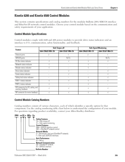
Kinetix 6200 and Kinetix 6500 Modular Multi-axis Servo Drives Chapter 5Kinetix 6200 and Kinetix 6500 Control ModulesThis section contains specifications and catalog numbers for the modular Bulletin 2094 SERCOS interface and EtherNet/IP network control modules. Choose your control module based on the communication and safety requirements of your application.Control Module SpecificationsControl modules couple with IAM and AM power modules to provide drive status indicators and an interface to I/O, communication, safety functionality, and feedback.Control Module Catalog NumbersCatalog numbers consist of various characters, each of which identifies a specific option for thatcomponent. Use the catalog numbering table chart below to understand the configuration of your module. For questions regarding product availability, contact your Allen-Bradley distributor.Feature Safe Torque-offSafe Speed Monitoring2094-EN02D-M01-S02094-SE02F-M00-S02094-EN02D-M01-S12094-SE02F-M00-S1Ethernet ports 2121SERCOS ports –Rx/Tx –Rx/Tx DC Bus status indicator √√√√Network status indicator √–√–Module status indicator √–√–Drive status indicator –√–√Comm status indicator –√–√Safety lock status indicator ––√√PORT 1 status indicator √√√√PORT 2 status indicator √–√–IOD connector for I/O, safety, and auxiliary feedback√√√√MF connector for motor feedback√√√√Axis Performance 02 = 500 µsBulletin NumberControl FeaturesM00 = SERCOS interface control M01 = EtherNet/IP network control Safety Features S0 = Safe torque-offS1 = Safe speed monitoring Network MediaD = Twisted pair, dual port (EtherNet/IP network)F = Fiber optic (SERCOS interface)Network Communication EN = EtherNet/IP network SE = SERCOS interfaceChapter 5Kinetix 6200 and Kinetix 6500 Modular Multi-axis Servo DrivesKinetix 6200 and Kinetix 6500 General System SpecificationsThis section contains environmental, weight, power dissipation, circuit breaker/fuse, transformer, and contactor specifications.Environmental SpecificationsWeight SpecificationsAttributeOperational Range Storage Range (nonoperating)Ambient temperature 0…50 °C (32…122 °F)-40…70 °C (-40…158 °F)Relative humidity 5…95% noncondensing 5…95% noncondensing Altitude 1000 m (3281 ft)3000 m (9843 ft) with derating3000 m (9843 ft) during transportVibration 5…***********(0.014in.)doubleamplitude,continuousdisplacement;55…**********************acceleration (10 sweeps in each of 3 mutually perpendicular directions)Shock15 g, 11 ms half-sine pulse (3 pulses in each direction of 3 mutually perpendicular directions)IAMPower Module Cat. No.Weight, approx.kg (lb)AMPower ModuleCat. No.Weight, approx.kg (lb)IAM (460V)2094-BC01-MP5-M 5.67 (12.5)AM (460V)2094-BMP5-M 3.18 (7.0)2094-BC01-M01-M 5.67 (12.5)2094-BM01-M 3.18 (7.0)2094-BC02-M02-M5.90 (13.0)2094-BM02-M3.40 (7.5)Kinetix 6200 Control Module Cat. No.Weight, approx.kg (lb)Kinetix 6500 Control Module Cat. No.Weight, approx.kg (lb)SERCOS interface2094-SE02F-M00-S00.68 (1.5)EtherNet/IP network 2094-EN02D-M01-S00.68 (1.5)2094-SE02F-M00-S12094-EN02D-M01-S1Chapter 12Motion Control AccessoriesInterface Cable CombinationsCable length xx or x-x is in meters. Refer to Standard Cable Lengths beginning on page 393.Cat. No.Cable Description Drive Compatibility 2090-UXPC-D09xx Serial cable to computer, 9-pinUltra3000/5000 drives2090-U3CC-D44xx (1)(1)This cable does not carry the unbuffered motor encoder signals (CN1 pins 10-15). Contact your Allen-Bradley sales representative if these signals are required for yourapplication.CN1 connector to flying leads for 1756-M02AE module, 44-pin, single-axis cableUltra3000, Ultra3000 with indexing drives andUltra3000-DN, Ultra3000-DN withindexing drives 2090-U3AE-D44xx (1)CN1 connector to premolded 1756-M02AE module connector, 44-pin, two-axis cable 2090-SCEP x-x SERCOS fiber optic plastic cables suitable only for use inside an enclosure. Connectors are provided at both ends.ControlLogix 1756-M xx SE modules toKinetix 2000, Kinetix 6000, Kinetix 6200, Kinetix 7000, and Ultra3000-SE drives 2090-SCVP x-x SERCOS fiber optic plastic cables suitable for use outside an enclosure. Connectors are provided at both ends.2090-SCNP x-x SERCOS fiber optic plastic cables suitable for use outside an enclosure in harsh duty applications. Connectors are provided at both ends.2090-SCVG x-x SERCOS fiber optic glass cables suitable for use outside an enclosure. Connectors are provided at both ends.2090-S-BLHD SERCOS fiber optic cable bulkhead adapter (2 per pack).1202-C02Drive-to-drive safety cable for connecting single-wide Kinetix 6000 axis modules.Kinetix 6000 drives with safe-off feature (2094-BC xx -M xx -S and 2094-BM xx -S) and Kinetix 7000 drives (2099-BM xx -S)1202-C03Drive-to-drive safety cable for connecting double-wide Kinetix 6000 axis modules.1202-C10Drive-to-drive safety cable for connections between two Kinetix 6000 power rails, two Kinetix 7000 drives, or from the Kinetix 6000 power rail to Kinetix 7000 drive.1585J-M8CBJM-x Double-ended (shielded) Ethernet cables for use when programming the safety configuration and the Logix EtherNet/IP network module.2094-SE02F-M00-S0 or 2094-SE02F-M00-S1Kinetix 6200 control modules and 2094-EN02D-M01-S0 or2094-EN02D-M01-S1Kinetix 6500 control modules1585J-M8CB-x Single-ended (shielded) Ethernet cables for use when programming the safetyconfiguration and the Logix EtherNet/IP network module.1585J-M8CC-H RJ45 insulation displacement connector (IDC) for use when making your own cables.1585-C8CB-S xxx Shielded Ethernet (bulk) cable for use when making your own cables.2090-DAPC-D09xx Ultra1500 serial interface to computer Ultra1500 drives 2090-DAIO-D50xxx Ultra1500 control interface to flying leads2090-U5PM-D09xx Ultra5000 to PanelView 300 Micro, 1761-NET-ENI, and MicroLogix DF-1Ultra5000 drives2090-U5PV-D09xx Ultra5000 to PanelView 300 Keypad 500/600/1000 Standard DF-12090-XXNRB-10F0P5Resistive Brake Module (RBM) to drive interface cable, 10 AWGKinetix 6000/Kinetix 6200/Kinetix 6500 drives 2090-UXNRB-10F1P3Ultra3000 drives2090-XXNRB-8F0P6Resistive Brake Module (RBM) to drive interface cable, 8 AWG Kinetix 6000/Kinetix 6200/Kinetix 6500 drives 2090-UXNRB-8F1P4Ultra3000 drives 2090-UXNRB-6F1P5Resistive Brake Module (RBM) to drive interface cable, 6 AWG Ultra3000 drives。
United KingdomAgriculture Automotive and Part Manufacturer AviationBuilding and Construction Chemical Industries Foundry General Industry Glass Industries Green SpacesIndustrial Cleaning Iron and steel industry Laboratory Maintenance Medical and Pharmaceutical Metal steel Paper Industries Ship Building Textile Industries Utilities Water treatment Welding Wood IndustriesReference NumberN06575003LProduct TypeRespiratory ProtectionRangeReusable APRLineFilterBrandHoneywellBrand formerly known asNORTHIndustryProduct UseControls before useUsers must:• Ensure that the level of protection offered by the respirator is sufficient for the type and concentration ofcontaminant(s) in the work area.• Respect the shelf life figuring on the filter.• Check the seal points.OverviewFeaturePerformance requirements for gas above standard.BenefitExcellent filtration efficiency over extensive period of time.FeatureLower profile and lightweight.Features & BenefitsHoneywell class 1 plasticcartridge A1B1E1PRODUCT NUMBER: N06575003LThe A1B1E1 cartridge is part of the wide choice ofcartridges offered to protect against many hazardousgases, vapors in many applications. The Honeywellrange provides high quality and a cost-effectiveprotection. The cartridges of class 1 Honeywell rangeare tested against the European standards EN14387.BenefitOptimal comfort.FeatureLow profile.BenefitDo not obstruct the field of vision.FeatureThreaded connector.BenefitEasy to attach.FeatureSmall opening.BenefitEasy check up.ReusableFilter Cartridge Connection TypeN-SeriesWeight103.9 g (80 x 50 mm)E.C. Declaration of ConformityEC Category PPE3Quality AssuranceISO 9001 / 2000EC Certificate Number2259EC AttestationCE certificate - Honeywell class 1 cartridgesEC Attestation Number2259CertificationsEN 2259Class 1 Honeywell cartridges/supplementary/documents_and_downloads/respiratory_protection /reusable_respirators/4294979140/1033.aspxUser ManualUser instructions Honeywell Class 1 cartridges - multilingualLife Cycle6 yearsService life :The useful life of filters depends on the absorbent, the concentration in the contaminated air,the relative humidity, the ambient temperature and the type of work being done.• All gas and combination filters should be discarded no longer than six months after opening, irrespective of the number of periods of use.• Particle and combination filters must be replaced when breathing becomes difficult.Storage InformationFilters should be stored in their original packaging in a cool, dry, non contaminated atmosphere. Storage under conditions other than those specified by the manufacturer may affect the shelf life.Temperature range of storage conditions: -10°C/+40°CMaximum humidity of storage conditions: 90% RHCare InstructionsConditions of use (temperature range, maximum humidity, etc.) :Temperature range : -10°C/+40°CMaximum humidity : 90% RHRestrictions of use :In an explosive atmosphere.• In highly toxic atmosphere. Refer to AS/NZS1715 or EN 529.• If the concentration of oxygen is less than 19.5% by volume or in an oxygen enriched environment.• If the package unsealed or damaged.• If the concentration exceeds Maximum Usage Concentration. Refer to governing standardAS/NZS1715 or EN 529.Quantity per Box/Pack/CaseShipping box (6 pairs/12 units) / Shipping case (8 bx/96 u.) - 11.53 KgCountry of OriginUnited States© Honeywell International Inc.。


Sensors and Switches for Valves and Flow Meters An Application NoteBackgroundFlow meters can measure and regulate volumetric flow, velocity from which the volumetric flow is determined, and mass flow. Valves control or regulate the flow of gases or fluids by partially obstructing, opening or closing the pipeline that carries the media. In many applications, they are operated manually by a lever, pedal, or wheel. Valves are often used in oil and gas, chemical manufacturing, water reticulation and mining applications. Automatic valves with diaphragms or pistons are often actuated by changes in pressure, temperature or flow.SolutionsHoneywell manufactures a wide range of sensors and switches, from simple on/off switches to electronic sensors designed to deliver system control, fluid level indication, temperature regulation, along with protection from overheating and starting/stopping the compressor. Honeywell components provide enhanced reliability, minimize down time, and improve robustness in most harsh environments.Various package options are available, including stainless steel, and those designed for hazardous and harsh-duty applications.Hazardous-location limit switches – These specialized switches perform a number of functions, including monitoring the position ofthe valve stem, actuator or wheel position, providing on-off position on manual process valves, providing real-time valve status information for improved productivity and safety. As these limit switches are enclosedin an explosion-proof housing, any flame path is extinguished inside which mitigates the risk of causing an explosion at the switch part.These switch components provide feedback for the user to take actionin order to prevent explosions in hazardous environments. Hazardous-location switches are employed in valves in outdoor, above-ground, potentially explosive environments such as oil and gas or water treatment applications.Limit Switches – Employed to monitor the position of the valve stemor actuator, limit switches are primarily used on valves in non-explosive environments such as waste water treatment plants, power generation plant or other factory applications. They also allows users to remotely monitor the valve stem, actuator lever, or wheel position for improved productivity and reduced total installed cost in hazardous locations.Figure 1. Industrial Valve ApplicationValves serve a variety of purposes in industrial applications, although their main purpose is to control media through a system.Wireless Limit Switches – Allows users to remotely monitor valve stem, actuator lever, or wheel position for improved productivity and safety, while reducing total installed cost with an economical wireless point-to-point solution.Basic Switches –Snap-action switches monitor the position of the valve handle by indicatingif the switch is actuated. These switches are employed on valves used in both non-explosive environments such as waste water treatment plants and/or other factory applications and also explosive/hazardous applications. Invalve monitoring applications, basic switches perform position sensing on cams with no power consumption. In addition to valves, Honeywell’s V15W2 Series is suitable for use in hazardous environments such as refrigeration, HVAC,appliances, and paint booths.Hall-effect Speed Sensors and Sensor ICs – In flow meter applications Honeywell’s speed sensors measure flow by monitoring revolutions of the impeller (an inside propeller). Eachrevolution of the impeller equates to the delivery of a certain amount of fluid. For example, if the user sets a fluid level of five gallons per minute,the speed sensor counts the impeller rotation so that the correct amount of fluid is delivered. Invalve monitoring application, Hall-effect sensor ICS measure position sensing on cams.Position Sensors – In flow meter applications, Hall-effect magnetic position sensors are usedto determine valve position. In valve monitors, position sensors deliver continuous position status with enhanced reliability and accuracy.Pressure Transducers and Switches – In valve actuator applications, pressure transducers and switches measure the pressure of the diaphragm to help regulate and control the flow within the pipeline. The sensors can measure differential pressure by comparing values across the valve. They can also give an indication of valve position related to opening and closing by measuring the pressure value at that time.Snap-Action SwitchPosition SensorSMART Position SensorHall-Effect Position Sensor ICwith Actuatorsin hazardous locationsLimit SwitchLearn more aboutthe XYR6000OneWireless™ SensorClick here to view Hazardous Area Limit SwitchesRead more about MICRO SWITCH Limit Switches12Explosion-Proof Valve Position IndicatorMICRO SWITCH VPX • Valve position indicator in explosion-proof housing2334Basic SwitchMICRO SWITCH BZ, V7, V15, V15W2, and ZW Series • Large, miniature, and subminiature basic switchesHazardous Location Limit SwitchMICRO SWITCH LSX, CX, and BX Series • Premium limit switches in explosion-proof housingLimit SwitchMICRO SWITCH HDLS, GL, and Double Break Series • Premium heavy duty and standard global limit switches14Figure 4. Switches in Valve Actuators and PositionersClick here to view VPX Series Valve Position IndicatorsGet details on the SMART PositionSensor familyFigure 5. Sensing and Switching Products Used in Valve ActuatorsHazardous Location Position Sensor XYR6000 OneWireless™ SeriesAllows users to remotely monitor valve stem, actuator lever, or wheel position for improved productivity and safety, while reducing total installed cost in hazardous locations; part of a scalable ISA100 mesh networkHazardous Area Limit SwitchMICRO SWITCH™ LSX/CX/BX/EX SeriesMonitors valve stem, actuator lever, or wheel position, providing real-time position status for improved productivity and safety in hazardous locationsLimit SwitchMICRO SWITCH™ HDLS, GLS, and Double Break SeriesMonitors valve stem, actuator lever, or wheel position, providing real-time position status for improved productivity and safetyPosition SensorSMART Position Sensor, SPS Series 75 mm Linear Monitors valve stem or actuator position1234Stainless Steel Media Isolated Pressure Sensor or Pressure Switch MLH, PX2, or PX3 Series Pressure Sensor or HP, HE, ME, LP, or LE Series Pressure SwitchMeasures diaphragm pressure6Valve Actuator(Kammer valve actuator photoused with permission of Flowserve.)Wireless Limit SwitchMICRO SWITCH™ HDLS and GLS SeriesAllows users to remotely monitor valve stem, actuator lever, or wheel position for improved productivity and safety, while reducing total installed cost with an economical wireless point-to-point solution5Learn more about MICRO SWITCH Basic SwitchesReview Limitless™ Wireless SwitchesFind out more on Hall-effect Speed SensorsFigure 6. Sensing and Switching Products Used in Valves and Flow MetersSMART Position Sensor SPS Series75mm analog and 225 mm analog and digital linear configuration Position Sensor SR SeriesDigital position sensorHall-Effect Sensor LCZ or 3000 SeriesSingle, zero speed sensor (LCZ) or high resolution VRS sensor (3000)Basic SwitchMICRO SWITCH BZ, V7, V15, V15W2, and ZW SeriesLarge, miniature, and subminiature basic switchesHazardous Location Limit Switch MICRO SWITCH VPX, CX, LSX, and BX SeriesPremium limit switches in explosion-proof housingLimit SwitchMICRO SWITCH HDLS, GLS,and Double Break SeriesPremium heavy duty and standard global limit switchesFlow MeterClick here to view Pressure TransducersMore information available here on Hall-effect Sensor ICsTypes of ValvesSpecifically, there are several main types of valves: 1) Manual process valves, 2) Valve actuators/positioners, 3) Valve monitors/indicators, 4) Valves and flowmeters, and 5) Sanitary and food/beverage valves.Manual Process Valves – Manual process valves in industrial facilities control the flow of liquid, gas, slurry, or steam. Eighty percent require operators to manually open, close, or otherwise control the valve. At any given time, users may not know the actual position of the valve. Process plants, including refineries, chemical, pharmaceutical, and water treatment plants as well as power generation installations, all need a better way to verify status with or without human intervention, especially in hazardous or hard-to-reach locations. (See Figures 2 and 3)Valve Actuators/Positioners – A valve actuator is a pneumatic or electric mechanism used in process control systems to automatically open or close valves. Actuators can be used with either linear or rotary valves in industrial, medical, food/beverage, and transportation applications. In standard valves, when the valveis given a command to open to a certain point, there is no feedback to verify that it has opened to that position. Valve positioners utilize a source of power to operate and continuously adjust a valve. The power source can be a manual gearbox or an electronic device with control and measuring devices; Available with hydraulic, pneumatic, and electric operating mechanics, these are often used in pipelines, process plants and in remote areas. Postioners can be used for opening or closing a valve to control the rate of fluid flow based on a signal from a central control system. With a valve positioner, the command is given and the valve positioner reads the opening, verifies position, and readjusts (if necessary) to the exact position needed which allows for excellent precision in the valve setting. (See Figures 4 and 5)Valve Monitors/Indicators – Mechanical or electrical valve monitors and indicators are used in process control to show valve position. They provide an electrical signal, and sometimes visual feedback, to accurately monitor and verify that a valve is in the correct position. Valve monitors are mostly used in conjunction with a valve positioner/actuator to provide information from remote locations that are not easilyaccessed, or where power isn’t readily available. Potential applications include chemical, pharmaceutical, power generation and oil and gas processes. (See Figures 4 and 5)Valves and Flowmeters – Valves control or regulate the flow of gasses or fluids by partially obstructing, opening or closing the pipeline that carries the media. Valves are often usedin oil and gas, chemical manufacturing, water reticulation and mining applications. In many of these applications, the valves are operated manually by a lever, pedal or wheel. Automatic valves with diaphragms or pistons are often actuated by changes in pressure, temperature or flow.Flow meters can measure and regulate volumetric flow, velocity from which the volumetric flow is determined, and mass flow. The turbine flow meter translates the mechanical action of the turbine rotating in the liquid flow around an axis into a user-readable rate of flow (gpm, lpm, etc.). The turbine wheel is set in the path of a fluid stream. The flowing fluid impinges on the turbine blades, imparting a force to the blade surface and setting the rotor in motion. Nearly all flow meters mustbe installed so that there is a significant runof straight pipe before and after the locationof the flow meter. This is intended to allow the straight pipe run to “smooth out” any turbulence produced by the presence of valves, chemical injectors and diffusers, and changes in pipe direction. (See Figure 5)Sanitary and Food/Beverage Valves – Sanitary and food and beverage valves are engineered for pressure control in sanitary (or “clean”) environments. They are usually manufactured with stainless steel for sanitary and high-purity applications. These valves are often constructed as a ball valve around a fullbore design that ensures the product passes through the valve with no restrictions on the flow with minimal pressure drop.Sanitary and food and beverage valves are often found in pharmaceutical, biotechnology, food and beverage, cosmetics, chemical and other industries where sanitary process control is required for steam, gases, and liquids such as water-for-injection systems.000697-7-EN | 7 | 04/21© 2021 Honeywell International Inc.Honeywell Advanced Sensing Technologies830 East Arapaho Road Richardson, TX 75081 /astFor more informationHoneywell Advanced Sensing Technol-ogies services its customers through a worldwide network of sales offices and distributors. For application assistance, current specifications, pricing or the nearest Authorized Distributor, visit /ast or call:Asia Pacific +65 6355-2828Europe +44 (0) 1698 481481USA/Canada+1-800-537-6945Warranty/RemedyHoneywell warrants goods of its manufacture as being free of defective materials and faulty workmanship during the applicable warranty period. Honeywell’s standard product warranty applies unless agreed to otherwise by Honeywell in writing; please refer to your order acknowledgment orconsult your local sales office for specific warranty details. If warranted goods are returned to Honeywell during the peri-od of coverage, Honeywell will repair or replace, at its option, without charge those items that Honeywell, in its sole dis-cretion, finds defective. The foregoing is buyer’s sole rem-edy and is in lieu of all other warranties, expressed or implied, including those of merchantability and fitness for a particular purpose. In no event shall Honeywell be liable for consequential, special, or indirect damages.While Honeywell may provide application assistance per-sonally, through our literature and the Honeywell web site, it is buyer’s sole responsibility to determine the suitability of the product in the application.Specifications may change without notice. The information we supply is believed to be accurate and reliable as of this writing. However, Honeywell assumes no responsibility for its use.m WARNINGPERSONAL INJURYDO NOT USE these products as safety or emergency stop devices or in any other application where failure of the product could result in personal injury.Failure to comply with these instructions could result in death or serious injury.m WARNINGMISUSE OF DOCUMENTATION• The information presented in this product sheet is for reference only. Do not use this document as a product installation guide.•Complete installation, operation, and maintenance information is provided in the instructions supplied with each product.Failure to comply with these instructions could result in death or serious injury.。

IS-6500培训文档第一章设备总概IS-6500是霍尼韦尔最新推出的一款数字可视对讲主机,使用7寸电容式触摸屏。
外观简洁大方,安装方便,可以搭配各种装修风格的家居设计。
使用TCP/ip的网络进行通讯,最大程度上简化了传统可视对讲在综合布线上的复杂程度。
但此款设备没有自动化控制功能,如果在设计单户型智能家居时可以配合HRIS-1000使用。
●设备参数如下:系统内核:WIN CE电源:DC 12V尺寸:260(H)*160(V)*18(D)重量:650g使用温度:-10~40摄氏度环境湿度:0~80%功耗:平时4W,最大25W●安装环境网络接口:普通TCP/ip网络接口,RJ45接口,与园区对讲网络通讯。
第二章设备外观及名称1、正面各部分的介绍2、背面各个接口的介绍第三章 设备安装此设备为壁挂式安装,所有线缆可以从预埋的86盒中穿出,也可以使用比较大的底盒。
注意:如果配合无线数字门锁使用时,注意预留出无线门锁的无线发射器的位置。
1、 将挂机板的左侧或右侧箭头顶点对准86盒左侧或右侧边缘,箭头朝上放置挂机板,在挂机版的4个安装孔处做标识。
2、在标识的位置钻4个孔,然后敲入膨胀螺丝管3、将膨胀螺丝穿过挂机板的安装孔敲入膨胀螺丝管,并拧紧螺丝,紧固挂机板4、随机附带的接线端子接好后预留在86盒的外面,随时可以接到机器上。
5、将主机挂装在挂机板上。
第四章系统功能本部分将要系统的介绍6500系统实现的各个功能,主要分为访客记录功能、通话功能、物业管理功能、电梯控制功能、家居安防功能。
一、访客记录功能访客记录是通过单户门口和单元门口机抓拍的图像生成的,6500与单元门口机是通过TCP/IP的网络通讯的,而与单户门口机是通过模拟信号通讯,下图是6500后背板的单户门口机的接口及释义:RJ45的水晶头使用568B的线序接线,此接口可以连接前后门两个小门口机,如果使用HONEYWELL数字门锁的话可以分别开启前/后两个入户门;但是如果使用电控锁开门的话只能开启前门。
PA/V A SOLUTIONSVARIODYN D1Digital Public Address andVoice Alarm System2 | Voice Alarm is increasingly important in the safe management of buildings. A voice message informs occupants exactly what to do in an emergency and it is a long established fact that people respond more quickly and are more likely to take the correct action during an evacuation if voice messages are used instead of tone sounders.THE ROLE OF VOICE ALARM• Clear directions to people in the building• Live messages giving exactinstructions to people whoare not familiar with the surroundings • Customised pre-recordedmessages (available inmultiple languages)• Up to 20 minutes shorter response time to fire alarm• Serial Interface toHoneywell fire panels for EVAC guidance and time-controlled evacuation • High-end non-emergency features such asequalizing, automatic volume control and multi-channel announcements as well as backgroundmusic • Alarm cancellation and manual evacuation override controlBENEFITS | 3PUBLIC ADDRESS -MORE THAN VOICE ALARMVoice Alarm systems are more frequently used as public address and entertainment systems than only as automatic evacuation system inpublic buildings with a high number of visitors.• Paging and evacuation with zone-dependent messages • Integration with airport/train station managementsystems• Multiple channel/zone music broadcasting • Sport/concert hall and stadium sound systemintegration • Time-scheduled announcements• Touch screen operation panels• Operation from intuitive computer management systems • High quality background music for high class shopping experienceFEATURES PUBLIC ADDRESS PROVIDES ADDITIONALL Y:4 |Selecting, designing and commissioning a PA/VA system can be challenging. At Honeywell we have a team of experts that will help you build the most suitable system for your building.The first step is to decide exactly what type of PA/VA system you will need. This will largely depend on the size and functional complexity of your building.The following two types of systems are available that start from small ‘Compact Solution’ packages suitable for single storey buildings such as shops and offices and move up to a custommade ‘Modular System’ that will consist of a number of distributed systems linked together for large structures such as exhibition fairgrounds and airports.VOICE ALARMCOMPETENCE FOR YOU• Controlling and indicating equipment certified to EN 54-16 and EN 54-4• Complete range of EN 54-24 certified loudspeakers • Flexible systems that supports both simple and the most complex communication needs • High quality digital audio matrix• Intuitive touchscreen Graphical User Interface that manages the entire system • Phased evacuation scenarios • Situation, location & evacuation phasedependent voice messages • Exact guidance regarding evacuation routes• Freely configurableevacuation scenarios with logical dependencies • Dedicated Honeywelldesign and project supportSYSTEMS KEY FEATURES |5 LEISURE COMPLEXES SCHOOLS SMALL HOTELS OFFICESTHE COMPACT SOLUTION:COMPRIO D1An easy-to-install PA/VA system.Suitable for small to medium buildingswith up to 24 loudspeaker zones.APPLICATIONS• Leisure complexes• Supermarkets• Schools• Hotels• OfficesBENEFITS• Amplifier with build-in PSU available• ‘Off the Shelf’ Package• Installation within two hours• Only 8 HU rack space incl. amplifier,charger and batteries• Ensured compliance to ENstandards• Complete solution for up to 24zones• max. 2000 W output powerexpandable with additional DOM/AMPs6 | Our PA/VA systems can be distributed and networked together to deliver the most comprehensive and powerful solution for a wide range of applications. Suitable for mid to large and complex sites.THE MODULAR SOLUTION V ARIODYN D1• Industrial facilities • Universities• Airports and transport hubs • Stadiums• Exhibition halls and fairgrounds • Mega Shopping Malls • Large Office buildingsAPPLICATIONS• Scalable and modular to adapt to constant changes and demands• Supports a large number of evacuation and/or paging zones • Manages complicated evacuation strategies in the event of an emergency • IP connectivity tolink multiple nodes (VARIODYN D1 DOM)BENEFITS• Up to 120 announcements at the same time• Pre-recording and playbackof messages• Secured data link to various Honeywell Fire Alarm Systems• Decentralized and redundant system architecture• Interface to BuildingManagement Systems (e.g. Honeywell EBI)• Redundant network and Call Stations linksComputer Management Station (PAMMI)Decentralized | 7STADIUMS AIRPORTS SHOPPING MALLS RAILWAY STATIONSCUSTOMISED CONTROLThe PAMMI (Public Announcement Man Machine Interface) software provides monitoring and control of the Honeywell Voice Alarm System via a graphical user interface on a Microsoft Windows® based personal computer.PERFECT SYMBIOSIS VOICE ALARM AND FIRE ALARMAREA BY AREA, TARGETED AND ORDERL Y:EVACUATION PROCEDURE EXAMPLE AT THE AIRPORT• There is a short-circuit in the baggage sortingarea on the 1st sub-level,section B of the airport. • The fire detector detects the formation of smokeand transmits theinformation to the firealarm control panel.• The fire alarm system simultaneously initiatesalarms to the securityservices and the voicealarm system.• The security inspectorassesses the situation viathe video camera installedon-site and then activatesa stored a nnouncementto the personnel with thepush of a button.• Due to the increasingformation of smoke,the fire alarm systemautomatically closes thefire door in the affectedarea.Synergies arise through digital coupling of the fire alarm system with the voice alarm system, thus facilitating an orderly, area-specific evacuation during emergencies: If a fire is detected by the connected fire detectors and then received by the fire alarm control panel, this automatically activates the voice alarm system. The endangered areas are then selected automatically and informed via the PA/VA system, while at the same time the fire alarm control panel activates fire protection systems, for example, fire doors, air-conditioning and ventilating systems, elevator controls or smoke dampers.The combination of voice alarm and fire alarm technology not only offers functional advantages, there are economical advantages as well: PA/VA reduces the total EVAC time significantly, a PA/VA system is not much more expensive than standard sounders, while it adds valuable support by increasing productivity of building occupants.8 | | 9VARIODYN D1 AND COMPRIO PA/VA SYSTEM DIAGRAM Thanks to its modular construction and the varioussystem components, the VARIODYN D1 system can easily DCS Digital Call Station DSCF DSC for Firefighter Fire Alarm Control PanelInterfaceDOMAMP PSUDCSF 1/12Configuration via LaptopCD playerETCSDCS PlusCentral Operating Terminal(PAMMI, WINMAG, Honeywell EBI etc)Loop Isolator ModuleAdvanced,Automatic Volume Control10 | WINMAGPLUSONE MANAGEMENT SYSTEM FOR ALLPERFORMANCE FEATURES OF THE VARIODYN D1 INTERFACE WINMAGPLUS DRIVER• System configuration readout of a VARIODYN D1 network to take it over via import files to WINMAGplus application.• Fault and status indication of the VARIODYN D1 system components: • DOM, SCU, DAL bus devices like DCS and • UIM, Amplifiers (each channel)• Audio and control contact inputs and outputsThe WINMAGplus hazard management system lets you create a scalable software solution with superb levels of integration with different sub-systems.In case of Voice Alarm system, VARIODYN D1 is connected via Ethernet/RJ45 to the same network as the WINMAGplus server. This enables the VARIODYN D1 integration with systems such as: fire alarm, fire extinguishing, smoke and heat control, escape routes, CCTV, access control, intrusion detection, emergency lighting as well as BMS and others via open protocols.• Call station function: • Microphone switched to pre-selectable or fixed targets for live-spoken announcements• Playback of pre-recorded announcements onselectable or fixed targets• Display, update and controlof: • Volume• Volume presettings (min., max., alarm)• Audio signal levels • Control contacts | 11Client Ma chinesHazardManagementVideo SystemsIntrusion Detection SystemsAccess ControlPublic Address & Voice AlarmFire AlarmFireExtinguishingFireControlsEmergency LightingBuildingManagement Systems12 | CHALLENGING PROJECTS REQUIRE BEST DESIGN AND EXPERTISEBY CEN/TS 54-32 EUROPEAN STANDARD VA SYSTEM CAN BE DESIGNED IN 2 WAYS TO ACHIEVE REQUIRED INTELLIGIBILITY: 1. Simplified, prescriptive method, requiring loudspeakers mounted every 6 meters or less.2. Detailed method, requiring in practice acoustics simulations as VA system design base regarding spacing, location, type selection, audio equalizing and proper orientation of loudspeakers.Acoustic simulations are paramount for a proper PA/VA system design in complex, tough and large areas. EN 50489 and CEN/TS 54-32 require minimum intelligibility level from installed VA systems. Installing and planning VA systems bears a risk of failure during intelligibily measurements in the handover phase. Toprevent such critical situations and underbudgeting of VA systems acoustic simulations are the only guarantee. |13EXAMPLE OF THE ACOUSTIC SIMULATION OF AN AUDITORIUM Acoustic simulation software provides to precisely and reliably assess sound pressure level (dB) and intelligibility level (STI/CIS). The software calculates the simulatedroom as a space map in 3D, enabling the user to verify the selected type, location and setting of loudspeakers.Voice Alarm system design for acoustically challenging areas must be based on professional, quality simulations,prepared by experienced acoustic experts.Our Technical Support Team provides expertise, experience, tools and wide portfolio of certified VA loudspeakers to assure our partners and system designers that Variodyn D1 system designs will pass acceptance tests.14 | VARIODYN D1 PRODUCT FAMIL YAll of the components of the VARIODYN D1 product family are compatible, interchangeable and optimally adapted to the customers growing needs. As varied as the requirements may be, all of the components are modular designed andcan be combined with each other quick and easy.ComprioComprio is a voice alarm system optimised for small and medium-size facilities such as schools,hotels, leisure centres and offices. It's characterised by its compact design, wide performance range and its flexibility.Digital Output Module (DOM)The Digital Output Module (DOM) is the heart of the Honeywell Voice Alarm and Public Address system. Managing either 8 or 24 zones the DOM routes up to 4 channels of audio from amplifiers to any individual zone or group of zones.Class D Power AmplifiersCombining the latest in digitalaudio technology with the integrity necessary for emergency Voice Alarm systems to satisfy the requirements of EN54 part 16.Direct Drive Power Amplifier4-channel Direct Drive Amplifier 4 x 300 W or 4 x 500 W power outputs or unit providing 4 x 125 W or 4 x 250 W power outputs with integral EN 54-4 certified battery charger.Paging Microphone DCSPlus The paging microphone allows for the selection of loudspeakerzones, and the transmission of voice announcements via programmable buttons.Ethernet Touch Call Station (ETCS)This EN 54-16 certified touch screen call station provides a user friendly, multilingual and multi-user interface support with high failure safety due to redundant transmission routes via Ethernet (PoE possible). It includes audio memory up to 27 hour and a USB stick can be connected to play audio files as well.Universal Interface Module (UIM)Interface module enables audio or control connection to third party systems such as CD players, security systems and other PA/VA or building management control systems.System Communication Unit (SCU)The System Communication Unit (SCU) is an integrated digital audio memory source able to simultaneously record and play back multiple audio data streams.PAMMI PublicAnnouncement User Interface The PAMMI software provides connection and control of the Honeywell Voice Alarm System via a graphical user interface on a Microsoft Windows ® based PC.Emergency Microphones Emergency Microphone used to select and broadcast pre-programmed alarm messages and live voice announcements during emergency situations by security operator or fire brigade commander. | 15LOUDSPEAKERSHoneywell offers loudspeakers, specially designed to meet various requirements and specifications in many project types e.g.Excellent acoustic performance to realize clear, understandable voice announcements or high quality background music.• Cost-effective types• Well designed, modern appearance• Easy for installation to reduce time, efforts and costs • Robust material to offer long lifetime•Models with ceramic terminal block and thermofuseCeiling Loudspeaker• Metal or plastic ceilingloudspeakers• Several power tappings withsimple setting• Partly dual-cone speaker toensure best audio performance • Appropriate for indoorapplications such as offices, warehouses, schools etcHorn Speaker• Clear voice messagereproduction for open and outside areas• Offers a high sound pressureand long-lasting weather resistanceSound Projector• Wide frequency response range,low distortion• Robust aluminum housing • IP65 rating• Best option for applicationssuch as corridors and railway platformsColumn Loudspeaker • Flat, directed soundpropagation, minimized reverberation• Intelligible voice and superiorsound reproduction • IP65 rating• Great choice for theme parks ,exhibition halls and any open, high-volume rooms with high reverberation time.Cabinet Loudspeaker• Simple power setting and easyinstallation• Practicable for wall mountapplication• Plastic, MDF or metal vandal-proof cabinetSpherical Loudspeaker• Where wall mount or ceilingmounting is not possible • Variable hanging height • 360° sound propagationSpecial Loudspeaker for tunnels• Specially designed and EN 54-24certified for tunnel applications • Boundary effect and loudspeakerphasing for best intelligibility inextremely difficult tunnel projectsEXTRACT FROM OUR EXTENSIVE PRODUCT OFFERINGS:00-0000 | DI | 01/ 21© 2021 Honeywell International Inc.Honeywell Building Technologies 715 Peachtree St. NE Atlanta, GA 。
Instrucciones de instalaciónJuegos de conectores de perfil bajo para señales de E/S, seguridad y retroalimentación auxiliarNúmero de catálogo 2090-K6CK-D44MAcerca de los juegos de conectores de perfil bajoEste juego de conectores de 44 pines ofrece puntos de terminación para E/S, conexiones de retroalimentación auxiliar y de seguridad para el conector IOD de las unidades Kinetix® 6200 y Kinetix 6500.El juego también incluye un puente habilitador de movimiento que se puede instalar cuando no se desea activar la funcionalidad de desconexión de par segura de los módulos de control 2094-xx02x-M0x-S0. El puente no es apto para los módulos de control 2094-xx02x-M0x-S1. Estos documentos contienen información adicional sobre el cableado de E/S, la seguridad y las conexiones de retroalimentación auxiliar para las unidades de servovariadores Kinetix 6200 y Kinetix 6500.2 Juego de conectores de perfil bajo para señales de E/S, seguridad y retroalimentación auxiliarRockwell Automation Publicación 2090-IN021D-ES-P - Enero 2015Cómo instalar el juegos de conectores de perfil bajoATENCIÓN: Este juego de conectores contiene piezas delicadas a descargas electrostáticas (ESD),que pueden sufrir daños si no se cumplen los procedimientos de control de ESD. Si no conoce los procedimientos de control de descargas electrostáticas (ESD), consulte la publicación n.º8000-4.5.2, Guarding Against Electrostatic Damage, o bien, cualquier otro manual de protección contra ESD que corresponda.1.Coloque el blindaje del cable expuesto en el canal.2.Conecte los cables a los terminales.3.Coloque la abrazadera de blindaje sobre el blindaje expuesto.4.Apriete los tornillos con un par de 0.4 N•m (3.5lb•pulg.).abrazadera para que los cables pequeños queden bien sujetos.Utilice abrazaderas de blindaje (3) para maximizar el contacto con el blindaje del cable en conexiones equipotenciales de alta frecuencia.Utilice sujetacables (4) para reducir la fatiga mecánica.Juego de conectores de perfil bajo para señales de E/S, seguridad y retroalimentación auxiliar 3Rockwell Automation Publicación 2090-IN021D-ES-P - Enero 2015Datos de los conectores(1)Los indicadores que se encuentran entre paréntesis hacen referencia al relé de seguridad Guardmaster® MSR57P y a los terminales de opción de seguridad serie 750 de PowerFlex®.(2)Utilice este suministro para alimentar la entrada de seguridad de 24 V (SPWR/SCOM). No conecte esta entrada de 24 V a ningún dispositivo de seguridad externo. Estos pines no son aptos para los módulos de control 2094-xx 02x -M0x S1.Instalación de puente habilitador de movimiento (aplica a los módulos de control 2094-xx 02x -M0x -S0).La numeración de pines del juego corresponde al conector IOD. Se asignan varios terminales a los pines 27, 28, 39 y 40 para que puedan adaptarse conexiones adicionales.Publicación 2090-IN021D-ES-P - Enero 2015© 2015 Rockwell Automation, Inc. Todos los derechos reservados. Impreso en EE.UU.Allen-Bradley, CompactLogix, Kinetix, MicroLogix, Rockwell Software y Rockwell Automation son marcas comerciales de Rockwell Automation, Inc.Las marcas comerciales que no pertenecen a Rockwell Automation son propiedad de sus respectivas empresas.Rockwell Automation mantiene información ambiental actualizada sobre los productos en su sitio web en/rockwellautomation/about-us/sustainability-ethics/product-environmental-compliance.page .Datos de los conectores (continuación)(1)Los indicadores que se encuentran entre paréntesis hacen referencia al relé de seguridad Guardmaster MSR57P y a los terminales de opción de seguridad serie 750 de PowerFlex.(2)Utilice estas señales como fuente de 24 VCC para operar las entradas digitales (máximo de 50 mA por entrada).Instalación de puente habilitador de movimiento (aplica a los módulos de control 2094-xx 02x -M0x -S0).La numeración de pines del juego corresponde al conector IOD. Se asignan varios terminales a los pines 27, 28, 39 y 40 para que puedan adaptarse conexiones adicionales.。
If you need detailed product information, or help choosing the right product for your application, see our Interactive Catalog . Use the Interactive Catalog to access the most complete and up-to-date information available.The Interactive Catalog provides an extensive collection of product specifications, application data, and technical literature that can be searched based on criteria you select.This PDF catalog information was published in November 2000.Sensing and ControlHoneywell Inc.11 West Spring StreetFreeport, IL /sensingSensing and Control Interactive Catalog...Click this icon to try the Interactive Catalog.Interactive Catalog Supplements Catalog PDFsBZG/BZH switches have a neoprene seal gasket between the housing halves, elas-tomer boot actuators, sealed conduit con-nectors, and die cast aluminum housing. Mounting holes are located outside the switch cavity and accept No. 10 screws. A neon pilot light can be added to switches having two conduit openings to indicate contact status.FEATURESɀPilot light (optional)ɀCast aluminum housingɀSide or flange mountACCESSORIESPilot Light 110-220 VAC (complete with seal) ............................................15LT1 Wiring Seal (for No. 14 type ‘‘S’’ rubber jacketed cord) ....................................2PA1 ELECTRICAL RATINGCircuitry Electrical RatingA UL Rating15 amp, 125, 250 or 480 VAC;2 amp, 600 VAC;MOUNTING DIMENSIONS(For reference only)PLUNGERSide mount Flange mount Roller plunger ROLLER LEVERSide mountFlange mount(2 conduit openings)RODFlange mount Side mount。
霍尼韦尔honeywell VISTA120中文说明书(上)1.产品以及系统的技术指标以及功能VISTA-120可以划分为8个子系统,最多支持128个由有线、总线或无线设备组成的防区,主要性能如下:· 对于5800EU系列无线设备,可以监测无线干扰,支持无线警号,监测时间缩短。
·通过对4101SN 和 4208UXM Mk3 的支持,继电器数量从32个增加到96个。
·增加了和PASSPOINT门禁系统的互动功能。
·支持自驱动警号。
·支持最终触发布防。
·系统布防时可选下载限制。
·防区9可用于电话线监测处理。
·可选择布撤防期间键盘的不同显示。
·对于序列号式总线设备支8倍的数据处理速度。
·防区列表数量从8个扩展到15个。
·可选择每个子系统可以被旁路的防区数量。
基础接线防区•防区2-8可选末端电阻监测,支持NO或 NC探测器•可以划分到任一子系统•防区1可以支持最多16个烟感探测器•防区1-8都可以使用4线烟感探测器•防区 8最多支持50个玻璃破碎探测器总线防区扩展:支持119个总线防区,最大电流128mA:•必须使用总线模块(RPM)•受主机监视•可以划分到任一子系统无线防区扩展:用5800系列无线设备最多可以有128个无线防区(若同时接有有线或总线防区,无线防区相应减少):•发射器发送安全信号供主机监视•可以监测发射器的电池状态•可以划分给任意一个子系统特殊监视防区J7 触发器输出防区 973无线接收机防区988, 990总线回路防区 997 外围设备支持最多32 和6139/5839EU 键盘混合连接的可编址设备,如无线接收机、继电器模块、4285电话模块等:•与键盘接在同一接线柱•每个设备一个唯一的地址•在设备编程中编程使用某个设备可选语音接口模块支持4286模块,以允许通过音频电话监控系统•获得系统状态信息•布撤防系统•控制系统继电器8个子系统整个主机分为8个子系统,每个子系统相当于一台主机•其中最多可以划分3个公共子系统,这3个公共子系统随相关子系统的布撤防状态而布撤防•主控子系统9可以通过一只键盘察看所有子系统状态•每个键盘可以指定给任意子系统•继电器也可以划分到子系统中•特定系统选项也可以按子系统分别设定用户密码整个系统可以设定150个密码,并且一个密码可以指定给多个子系统。