10000m_3球罐整体热处理强度及刚度计算_姚志燕
- 格式:pdf
- 大小:847.45 KB
- 文档页数:7


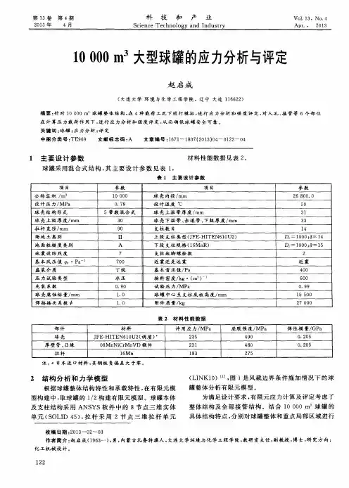
大型球罐整体热处理增效方法摘要:由于大型球罐在企事业单位的普遍应用,基于消除对球罐焊接后产生破坏性应力,本文从球罐热处理的原理及要点,利用数值分析对球罐加装导流装置前后的热处理效果进行比较分析,确定大型球罐整体热处理的增效方法。
关键词:大型球罐热处理数值分析导流装置引言随着化工产业的发展,大型球罐的需用量也随之增大。
然而大型球罐焊接完成后焊缝留有焊接残余应力,有的可达到材料屈服极限,危害极大。
为此大型球罐通常在焊后进行整体热处理[1]以稳定结构尺寸改善焊缝、热影响区的组织,使淬火组织软化,从而改善焊接接头的性能,降低硬度、提髙塑性、断裂韧度及疲劳强度。
工程中,球罐进行整体热处理时,壁面最大温差须控制在一定范围内。
目前对体积> 2000m?的球罐采用内部燃烧加热整体热处理很难达到工艺要求。
文献[2]研究表明,在球罐采用整体热处理时,髙温燃烧产物中的一部分直接由下人孔沿球罐中心轴对称从上人孔排出,对球罐壁面的传热几乎没有作贡献;而另一部分沿中心轴到达上人孔附近后,再沿球罐内壁向下人孔方向流动,同时与壁面发生热交换使壁面温度升高,并损失部分热量,使其向球罐下部流动时与罐壁面的热交换量逐步减少,导致球罐壁面温度从上向下依次降低,从而产生壁面温差。
对体积较大的球罐,上述热处理方法会使其壁面最大温差加大而超过工艺要求的范围。
由此可知,要尽可能消除壁而温差,需加强罐内燃烧产物的循环以及与球罐壁面的对流传热过程,并尽可能降低燃烧产物的直接排出。
通过在球罐内部添加导流板等装置以增加燃烧气流在罐内回转的强度形成良好循环,并使回转气流与壁而发生尽可能多的热量交换减小能量损失,从而降低壁面温差提髙热效率。
一、改进方法在文献[2]的基础上,改进球罐内部喷射燃烧整体热处理,用计算流体力学模型对其内部流场结构进行数值模拟,结果表明,热流控制装置是热处理成功的关键。
温控装置的使用避免了通常情况下整体现场热处理球体上部温度高于下部温度的难点。

球罐整体热处理温度场的非稳态计算及应用以球罐整体热处理温度场的非稳态计算及应用为标题球罐是一种常见的储存设备,常用于石油、化工等行业。
在球罐的制造过程中,为了提高其强度和耐久性,常常需要进行热处理。
而球罐整体热处理温度场的非稳态计算及应用是一个关键问题,本文将对其进行探讨。
我们来了解一下球罐整体热处理的过程。
球罐在制造过程中,通常会通过加热使其达到一定温度,然后再通过冷却使其温度下降。
这个过程是一个非稳态过程,即温度随时间的变化而变化。
为了确保球罐的质量和性能,需要对整个热处理过程进行全面的分析和计算。
在球罐整体热处理温度场的非稳态计算中,需要考虑多个因素的影响。
首先是球罐的几何形状和材料特性。
不同形状和材料的球罐在受热和冷却过程中会有不同的温度分布和变化规律。
其次是热源的温度和热传导等热学参数。
热源的温度和热传导对球罐的温度分布和变化速率有重要影响。
此外,还需要考虑外界环境的影响,如环境温度和风速等因素。
为了对球罐整体热处理温度场进行非稳态计算,可以采用数值模拟的方法。
数值模拟可以通过建立数学模型和求解偏微分方程来模拟和计算球罐的温度场。
这种方法可以有效地预测和分析球罐在不同条件下的温度变化规律,从而指导实际生产中的热处理过程。
除了计算球罐整体热处理温度场外,这个问题还有一些实际应用。
首先,通过对球罐整体热处理温度场的计算,可以优化热处理工艺参数的选择。
通过调整加热和冷却的温度和时间等参数,可以使球罐的温度分布更加均匀,从而提高其质量和性能。
其次,可以通过计算球罐的温度变化规律,来预测球罐在使用过程中的温度变化。
这对于球罐的设计和维护具有重要意义。
球罐整体热处理温度场的非稳态计算及应用是一个关键问题。
通过对球罐的几何形状、材料特性、热源温度、热传导等热学参数以及外界环境的考虑,可以通过数值模拟的方法进行非稳态计算。
这个问题的应用包括优化热处理工艺参数和预测球罐的温度变化规律。
通过对这个问题的研究,可以提高球罐的质量和性能,为实际生产提供指导。

球罐整体热处理[摘要]本文概述了球罐焊后进行整体热处理的目的、方法,并详细说明了为保证球罐整体热处理效果,采用燃油内燃法对球罐进行整体消除应力热处理的一般施工过程,以及进行整体热处理时的工艺控制。
[关键词]球罐、焊接、燃油内燃法、整体热处理中图分类号:tg162 文献标识码:a 文章编号:1009-914x(2013)05-0007-01球罐是指容积为200-10000m3的大型储存球形压力容器,其内径一般达7-26m左右,由于其体积庞大不便于运输,建造过程需分两个步骤进行,首先在工厂压制好球壳板,再将球壳板运到使用现场进行组焊而成。
由于球罐所盛装的介质大多为易燃易爆气体或液化气体,长期在较高的工作压力状态下运行,一旦发生爆破事故,将带来重大损失。
组焊时焊件的约束度较大以及现场组焊条件恶劣等原因,现场组焊后会产生较大的焊接应力,这是焊缝产生裂纹的基本因素之一。
为了消除焊接残余应力引发的裂纹,采用整体退火的热处理措施来消除焊接残余应力,目的是改善焊缝及热影响区的应力分布状态,降低或消除焊接残余应力,降低表面硬度,提高材料的韧性、塑性及球罐的耐疲劳强度,防止延迟裂纹的出现,保证球罐的使用安全。
1.球罐整体热处理方法球罐主体材料一般为低合金碳素钢,焊后整体热处理就是让焊接构件置于再结晶温度以上、临界温度acl点以下100-200℃(500-650℃)的条件下保温一定的时间后缓冷。
国内外对球罐整体热处理的施工方法有电加热法、燃油内燃法、爆炸法、以及化学加热法等,目前在我国电加热法及燃油内燃法的技术工艺较为成熟。
由于电加热法只适用于400m3以下的小型球罐,而燃油内燃法以热处理时间短、现场施工方便、成本低及适应性强等优点而被施工单位所普遍采用。
2.燃油内燃法热处理技术球罐整体热处理采用燃油内燃法进行,施工时将燃烧器安装在球罐的下人孔位置,以球罐本身为燃烧室,选用柴油为燃料,通过鼓风机送风和喷嘴将柴油喷入并雾化,由电子点火器点燃,随着燃油不断燃烧而产生的高温气流在球罐内壁对流传导和火焰热量辐射作用,使球罐不断升温至热处理工艺所要求的温度,同时球罐外表面包保温材料防止热量的散失。


10000 m3真空球罐的外压稳定性分析吴晓红;郭春光;李永泰;陈永东;倪利刚【摘要】通过对10000 m3真空球罐光壳和带加强肋不同方案的外压稳定性分析,结合经济性对比分析,确定10000 m3真空球罐球壳结构采用光壳结构;阐述了该球罐的外压工况的有限元分析结果。
%By analyzing the stability of external pressure of the 10000 m3 vacuum spherical tank without strengtheningribs and with different strengthening ribs,then comparing with the expense of the different constructions,reaching a conclusion that designing a 10000 m3 vacuum spherical tank without stiffening ribs is a better plan than designing with ribs;elaborating finite element analysis results of external pressure of this spherical tank.【期刊名称】《压力容器》【年(卷),期】2014(000)007【总页数】8页(P41-48)【关键词】真空球罐;加强肋;稳定性分析;有限元【作者】吴晓红;郭春光;李永泰;陈永东;倪利刚【作者单位】合肥通用机械研究院国家压力容器与管道安全工程技术研究中心,安徽合肥230031;合肥通用机械研究院国家压力容器与管道安全工程技术研究中心,安徽合肥 230031;合肥通用机械研究院国家压力容器与管道安全工程技术研究中心,安徽合肥 230031;合肥通用机械研究院国家压力容器与管道安全工程技术研究中心,安徽合肥 230031;合肥通用机械研究院国家压力容器与管道安全工程技术研究中心,安徽合肥 230031【正文语种】中文【中图分类】TH49;O343.90 引言风洞是飞机和火箭等航空航天飞行器研制过程中重要的地面试验设施,用以研究飞行器的空气动力学特性。
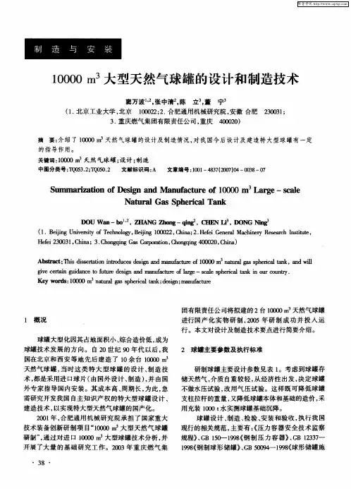
论10000m3天然气大型球罐基础设计方案朱 虹(北京市煤气热力工程设计院 100032)(Beijing Gas and Heating Project Institute) 摘要 本文采用有限元结构分析程序对大型球罐基础连同其上部结构进行了空间整体结构分析,揭示了基础结构的静动力特性,为基础结构设计提供了一种思路与方法。
关键词 有限元分析 沉降 空间结构体系ABSTRAC T This pape r offe re d space integrate d structure analysis to a foundation for the large sphe re with the uppe r structure by using the static and dynamic finite element structure analysis program.It showe d the static and dynamic charac te ristic of the foundationa and provid-ed a method for the foundation de sign.KEY WORDS Finite eleme nt analysis Settle ment Space integrate d structure system 引言本文针对10000m3天然气大型球罐基础结构设计,以基础和球罐作为整体结构模型,对其进行有限元空间结构静力及动力分析,揭示了结构的静力及动力性能,为基础结构的设计提供了全面可靠的设计依据。
球罐属于乙类构筑物,为重要的构筑物,球罐内存储高压天然气,如遭遇地震破坏会产生一系列灾难性后果。
一个球罐的经济投入约为US $3,000,000,所以其基础必须具有良好的安全可靠性,既要满足球罐正常工作时的各项要求,同时又应具备必要的抗震能力和安全储备。
3rd International Conference on Machinery, Materials and Information Technology Applications (ICMMITA 2015) LabVIEW Application to Heat Balance Calculation of Thermal Treatmentfor Large Spherical TankTingting Li1, a, Songling Ma1, b and Zhongbao Lu2, c1 Xi’an University of Architecture and Technology, Shanxi 710055, China2 Wuhan Yi Ye Steel Structure Co. Ltd, Hubei 430080, Chinaa****************,b***************,c****************Keywords: LabVIEW, Large spherical tank, Thermal treatment, Heat balance calculation.Abstract. Based on the basic formula of heat balance calculation, a computational simulation system is developed by LabVIEW, which is of thermal treatment for large spherical tank. This system takes full account of the size and material of spherical tank, and calculates the total quantity of heat and the consumption of oil for thermal treatment process of different spherical tank. This system solves these hard problems such as complex heat balance calculation process, a large amount of date calculation, dependence of personal experiences and so on. This system has been used for thermal treatment of spherical tank in practice. The calculation process is fast and reliable. In addition, the results can provide a strong help for the burner project bidding.1.IntroductionWith the formal establishment of the Asian Infrastructure Investment Bank (AIIB), as the second largest country of producing oil and chemical products, China need to promote the petrochemical products to the international. In petroleum refining industry and petrochemical industry, large spherical tanks are used for storage and transportation of liquid or gaseous materials widely, such as liquefied petroleum gas, liquid ammonia, oxygen, nitrogen. According to the production standards of the steel spherical tank, large spherical tank is manufactured by welding with arc steel plates [1]. So residual stress exists between these steel plates, which will reduce the rigidity and stability of structure. In order to eliminate the residual stress, the thermal treatment must be carried after welding [2].The key of post-weld thermal treatment of spherical tank lies in obtaining the theoretical value of combustor oil consumption in advance. Given that if the temperature of sphere shell fluctuates drastically in warming stage and thermal insulation stage during thermal treatment process, thermal treatment stress shall definitely generate [3]. As a consequence, researchers shall calculate some theoretical value. Chen [4] had summarized the steps of thermal calculation. However, owing to multiple influencing factors such as size, material and environment, thermal treatment technique complicates thermal calculation simultaneously, there is no complete mathematical models concerning thermal calculation aiming at simplifying calculation process. At present, thermal calculation of large-scale spherical can only depend on manual calculation, but such kind of calculation is time-consuming, labor-consuming and inaccurate.In conclusion, this paper adopts graphical programming (G language) and takes LabVIEW as the development platform software, which is a strong graphical user interface with various functions, constructing a system of simulation applied in thermal calculation during post-weld thermal treatment of large-scale spherical tank.[5]2.Functions of Thermal Calculation SystemThermal calculation of large-scale spherical tank is the premise of reasonable selection of thermal treatment device, pipe specification and process control parameters. According to the requirements of process development, the thermal calculation system should have following functions:Firstly, it shall select size of spherical tank independently and configure material of spherical tank randomly in order to satisfy different requirements of thermal calculation and realize universality.Secondly, it can store relevant standard data into the data base, and consequently, the system shall automatically retrieve relevant data in data base according to parameters such as size of spherical tank and material set by users. Thereafter, the system can formulate corresponding thermal treatment process and thereby saving time.Thirdly, it shall calculate thermal consumption amount and oil consumption amount during thermal treatment under complete working conditions and accordingly make consequences reports of thermal calculation. In accordance with calculation consequences, operators can reasonably control oil combustion amount during thermal treatment. In addition, designers can also set thermal treatment effects through controlling oil supply system fit for large-scale spherical in order to avoid thermal treatment stress.3.Design and Realization of Thermal Calculation SystemAt present, the thermal balance basic formulation is the most common thermal calculation method [2]. Based on thermal balance basic formulation method, this paper completes software development through LabVIEW platform. LabVIEW is a software developed by American National Instruments Corporation characterized by explicit graphical programming language (G language) and ideal programming code, and simultaneously, its graphical source code is similar to data flow chart to some degree. That is why LabVIEW graphical source code is also known as program chart code [6]. This thermal calculation system integrates three function modules in user interface, including parameter setup module, automatic calculation module and automatic generation reporting module. Modules realize thermal calculation function through internal parameter transmission or iteration.3.1Technological Route.As shown in Fig.1, this paper shall build a data base and store relevant standard data such as specific heat capacity and heat conductivity of various materials. The main program automatically selects relevant data as inline parameters according to user options, and further carries on thermal calculation based on parameters of thermal treatment set up by users as well as overall thermal calculation by calling subroutine.This system has a binary structure, among which the upper level is the user interface developed by LabVIEW working for parameter setup and display, and the lower level finishes thermal calculation report according to superior orders and relevant data.Fig. 1 System flow chart3.2Front Panel Design.(1) Parameter setting module of spherical tank. Large-scale spherical tanks mainly refer to tank with a volume over 5000 cubic meter, such as spherical tank of 50003m, 60003m, 80003m and 100003m volume. As shown in Fig.2, users can select common specifications from menu in the interface. This module also offers other shell steel plates with materials such as 20R, 16MnR, Q345R, Q370R, and 07MnNiMoDR as well as materials of insulating layer such as micro-glass fiber and alumina silicate fiber. In addition, the paper designs user input parameters such as thickness of spherical shell and thickness of insulating layer.Fig. 2 Parameter setting area of front panel(2) Inline parameter display module. When the material of the tank is set, the system shall automatically represent reasonable thermal treatment process according to common-used steel types mentioned in Welding Specification for Pressure Vessels (NB/T 47015-2011) such as target temperature, holding time, average warming rate in each temperature range and warming time as shown in Fig.3. At the same time, the system will generate the curve of specific heat and heat conductivity of shell materials and automatically display the inner diameter, outer diameter and quality of the tank according to Steel Spherical Tanks Type and Dimension Data Base (GB/T17261-2011).Fig. 3 Display Area of Inline Parameters in the front panel(3) Display module of calculation results. Pursuant to input design parameters and data base search results, the system shall automatically calculate data and display results as soon as users operate the program. Specifically, thermal value required in combustion process and oil consumption amount inunit time of each stage can be calculated and converted into overall oil combustion amount as shown in Fig.4. Then the system will generate thermal calculation report with user demands.Fig. 4 Display area of calculation results 3.3 Main Program Design.First of all, data including thermal conductivity and specific heat capacity of different materials shall be filled in spreadsheet files. The main program will retrieve file content through “File I/O” function panel to further screen out required data and combine them in the form of array as inline parameters. Fig.5 reveals partial program chart.Fig. 5 Read and screen data of Excel fileSecondly, researchers shall determine theory and experience equation in light of literature [2]. All necessary theories and experience equations in thermal calculation are all deduced on the basis of thermal balance basic formulation. During large-scale sphere post weld thermal treatment, overall thermal amount in unit time ∑Q shall be calculated by the following equation: ∑+++++=654321Q Q Q Q Q Q Q (1) Where 1Q refers to effective thermal amount in unit time when large-scale sphere shell material is heated, 2Q refers to missing thermal amount in unit time of insulating layer during thermal treatment, 3Q refers to missing thermal amount in unit time of insulation layer during storing thermal amount process, and 4Q and 5Q refer to missing thermal amount in unit time of combustor fuel during incompelete combustion, and respectively represent chemical incomplete combustion thermal losses and mechanical incomplete combustion thermal losses. 6Q refers to missing thermal amount in unit time during smoke extraction from sphere entrance. All above values and ∑Q take kJ/h as the unit. Calling subroutine shall be utilized in the calculation of values ranging from 1Q to 6Q as well as n B .Thirdly, researchers shall complete calculation display function of front panel through display control as shown in Fig.4. Thereafter, “reporting generation” button shall be set up in front panel. Researchers can generate Excel reports through “reporting generation” function panel in program chart.Finally, compiled programs have to be operated in upper computers in two ways. The first kind is to install LabVIEW, relevant driver and kit on target upper computers and then copy complete programs on them. The second one is to compile LabVIEW programs into independent executable programs (.exe file) on developing computers and thereby generating installation programs of executable programs and some relevant components [7]. In the second way, programs can be operated in target computers once the system is installed.3.4 Subroutine Design.Calling subroutine shall be utilized in the calculation of values ranging from 1Q to 6Q as well as n B . Take the 1Q calculation for example: ()mi i i i t T c T c m Q −=++1111 (2) Where 1m refers to the mass of spherical tank, kg; i T ,1+i T respectively refer to minimum and maximum temperature of i th range in the process of thermal treatment, 3,2,1=i ,C °; m t refers to the time from minimum temperature to maximum temperature in the i th temperature range, h ; i c ,1+i c respectively refer to specific heat when the temperature is i T and 1+i T , )/(C kg kJ °⋅. What should be paid attention to is that when 1=i , e i t T =. e t refers to the ambient temperature.Subroutine design is as shown in Fig.6, where three input ends and one output end are outlined by ligature panel on the front panel. Supposing that elected i T and i c exist in a form of array, then subroutine requires index array for further calculation in order to display calculation consequences in an integer. In comparison, the main program can directly adopt 1Q to calculate subroutine.Fig. 6 Program block diagram for 1Q calculationIn consideration of the fact that the design method of subroutine 2Q , 3Q , 4Q , 5Q and 6Q is similar to 1Q and all of them utilize literature [1] as basic calculation formulation, the following sections shall not repeat such content.4. Application ExamplesTaking a 60003m large spherical tank for example, select "6000" from "volume of spherical tank" menu in setting district, "Q370R" from "material of spherical tank" menu, and "Micro-glass fiber" from “the material of insulating layer” menu. In addition, the thickness of insulating layer has to be set up as 100mm, the thickness of the spherical shell 50mm, the ambient temperature 10C ° and wind speed 3m/s in the setting district. With the tank heat treatment parameters setting finished, run the program to get the inline parameter table and the thermal treatment process table of spherical tank as shown in figure 7.After users selecting and inputting parameters, this design platform will calculate required thermal amount in each stage by iterative calculation during opening the “Calculate” page, as shown in Figure8. Thereafter, required oil combustion amount under all working conditions can be calculated and calculation consequence reports can be generated. Calculation consequences are as follows: The calculation consequence of 1Q is h Kcal /106194×. The calculation consequence of 2Q is h Kcal /10924×. The calculation consequence of 3Q is h Kcal /10134×. The calculationconsequence of 4Q is h Kcal /10654×. The calculation consequence of 5Q is h Kcal /10254×. The calculation consequence of 6Q is h Kcal /103014×. The calculation consequence of B is kg 4286. Excel chart recording thermal treatment calculation consequences will automatically generate once clicking “report generation” button. Consequently, researchers can print large-scale sphere thermal calculation consequence reports if they input operator, company and table numbers in Office software or they just modify table form according to user demands.Fig. 7 User interface of parameters setting and inline parameters display5. SummaryIn this paper, a system of simulation, which is used for thermal calculation of large spherical tank, is designed based on the heat balance calculation formula. This simulation system can get the same calculation results as the conventional thermal calculation methods do [8, 9]. No matter what capacity or material the spherical tank is, this system can calculate the total calories per unit time and total fuel consumption accurately and rapidly, which are important parameters in the process of heat treatment, with the process, thickness of the shell plate, material and thickness of the thermal insulation layer into consideration. This system possess good generality, scalability and adaptability, providing accurate theoretical reference for the automatic control in heat treatment of spherical tank. Literature References[1]. Xingqing Yan, Jianliang Yu, Jian Wang. Flammable gas clouds resulted from the leakage anddiffusion of methane in a spherical tank. Journal of Safety and Environment. Vol. 15 (2015) No. 1, p. 83-87.[2]. Xiaoming Li, Baoguo Zhu, Feng Ji, et al. Heat balance calaulation of postweld heat treatment forcompleted spherical tank. Petro-chemical Equipment. Vol. 37 (2008) No. 4, p. 35-38.[3]. Jianqun Tang, Jianming Gong, Lijing Zhang. Failure analysis of a liquefied petroleum gasspherical tank made of 16MnR steel. Corrosion Science and Protection Technology. Vol. 17 (2005) No. 6, p. 432-434.[4]. Taiwei Chen. Post weld heat treatment technologies of pressure vessel. China PetrochemicalPress, 2002, p. 111-122.[5]. Wei Zhan, Jizhen Liu, Yanjun Li, et al. LabVIEW application to economic efficiency calculationfor thermal power plant. East China Electric Power. Vol. 39 (2011) No. 11, p. 1862-1865.[6]. .Ruilin Chen, Tianpeng Xi, Jinzhu Tan, et al. On neural network PID temperature control systembased on LabVIEW. Computer Applications and Software. Vol. 30 (2013) No. 12, p. 262-264.[7]. Zhou Jiang, Bo Peng, Liwen Wang, et al. Design and implementation of standardized designplatform for gas cooler. Dongfang Electric Review. Vol. 28(2014) No. 111, p. 1-11.[8].Liping Qu, Yongyin Qu, Zhonglin Li, et al. Computer monitor and control system of sphericaltank heat treatment. Control Engineering of China. Vol. 13 (2006) No. 13, p. 7-9.[9].Xiaoxiao Lv, Yihong Zhao, Huafeng Lu, et al. Numerical simulation and experiment research onheat treatment temperature field of 100003m spherical tank. Mechanical Engineering & Automation. Vol. 191 (2015) No. 4, p. 63-64。
1万立方球罐焊后热处理的工艺实验目录4焊后热处理(江都安大热处理工程公司和大学合作编写)4. 1焊后热处理工艺验证性试验14.1.1球罐主要设计参数14.1.2热处理方法及工艺规14. 1.2. 1热处理方法14.1.2.2热处理工艺规24. 1.3 热工计算24. 1.4热处理现场工艺设计74.1.4.1热处理工艺系统74. 1.4.2 保温方法104. 1.4.3试板与球罐壁板同步热处理114.2焊后热处理用燃烧装置及辅助装置(球罐温度均匀性与稳定性控制)114.2.1改造燃烧气流出口喷咀,保证燃气流螺族式上升114.2.2强制燃烧气流在球罐部的流动轨迹114. 2.3 适时维持球罐部正压力124. 3焊后热处理的技术保障措施134.4需要提供的数值、图表和照片144.4.1球罐焊后热处理总体照片144.4.2焊后热处理燃烧器照片144. 4. 3焊后热处理测温及控制照片144. 4. 4现场参加1万立方球罐焊后热处理的团队照片156 10000m3球罐焊后热处理结果156. 1 10000m3球罐焊后热处理报告156.2焊后热处理巡检记录151万立方球罐焊后热处理的工艺实验4焊后热处理(江都安大热处理工程公司和大学合作编写)4. 1焊后热处理工艺验证性试验10000m3球罐属III类压力容器。
根据设计要求和GB50094-2010,名义厚度大于30mm(当焊前预热100°C及以上时,名义厚度大于34mm)的Q345和Q370R钢制球形储罐必须经过焊后热处理。
本次热处理工程采用燃油法进行热处理,为确保热处理工程质量按技术要求顺利进行,特制定如下热处理实施方案。
4. 1.1球罐主要设计参数热处理依据及目的:本次热处理按设计图纸、GB 50094-2010和ASME相关标准进行整体热处理。
为了消除罐体组装与焊接时产生的残余应力,减缓介质对钢板的应力腐蚀,改善焊接接头和热影响区的组织和性能,达到降低硬度,提高塑性和韧性的目的,进一步释放焊缝中的有害气体,防止焊缝的氢脆和裂纹的产生,从而稳定容器的几何尺寸提髙设备的使用寿命。
大型球罐整体热处理改进方法与数值模拟
陈志华;涂善东;王正东
【期刊名称】《金属热处理》
【年(卷),期】2004(29)3
【摘要】大型球罐常用内部喷射燃烧的方法进行整体热处理 ,然而当球罐体积大于2 0 0 0m3时 ,此方法不能满足球罐整体热处理工艺的要求。
对加装反射板后的大型球罐进行整体热处理的过程进行了数值模拟 ,结果显示由于反射板的安装 ,球罐内部气流循环得到加强 ,球罐上下壁面温差降低 ,提高了大型球罐整体热处理质量 ,并能满足大型球罐整体热处理工艺要求。
【总页数】3页(P43-45)
【关键词】大型球罐;反射板;数值模拟;热处理
【作者】陈志华;涂善东;王正东
【作者单位】华东理工大学机械学院
【正文语种】中文
【中图分类】TG162.8
【相关文献】
1.基于瞬态数值模拟方法的球罐热处理温度场分布研究 [J], 姚志燕;吴晓红;李永泰
2.大型球罐整体热处理 [J], 薛公尧
3.导流伞位置对球罐焊后整体热处理影响数值模拟与分析 [J], 王荣;马容忠;贾尚谊;赵有伟;赵毅红
4.大型球罐整体热处理数值模拟 [J], 陈志华;涂善东;王正东
5.大型球罐整体热处理增效方法 [J], 罗涛
因版权原因,仅展示原文概要,查看原文内容请购买。