DS1232 看门狗芯片
- 格式:docx
- 大小:14.14 KB
- 文档页数:1

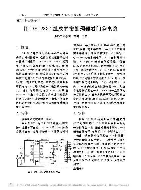
-44-《国外电子元器件》1998年第2期1998年2月●实用电路介绍用DS12887组成的微处理器看门狗电路后勤工程学院郭凌王丰图1DS12887硬件电路构成图1.概述DS12887是美国达拉斯半导体公司生产的实时时钟芯片,它作为微处理器的实时时钟被广泛使用。
IN T EL 8031、89C51系列单片机没有自身的看门狗电路。
使用DS12887作为它们的时钟芯片时可与单片机构成看门狗电路,能降低系统的成本。
原理在于利用DS12887的方波输出口(SQ W ,23脚),输出定时方波,该方波的频率最小可设定为2Hz ,可作为数字计数器的时钟输入,看门狗周期设定为 1.5s ,如果在DS12887产生2个方波之前不对计数器进行复位,则数字计数器输出一高电平作为单片机的复位信号,这样即可达到微处理器的看门狗功能。
2.硬件硬件电路构成如图1所示。
单片机8031与DS12887的微处理机接口这里不再重述。
DS12887的SQ W 脚为方波输出脚,它给计数器4017提供定时时钟脉冲,单片机的P10口与4017复位脚RST 相接(高电平有效),一旦P10口输出高电平脉冲,则4017被复位,Q 0端为1,Q 1~Q 9均输出低电平,4017重新开始计数。
4017的Q 3端输出的信号经二极管D1后到达单片机8031的复位端R ES 。
由于是Q 3输出复位信号,则4017的CL K 只需3个脉冲,Q 3即输出高电平信号,可预设DS12887的输出方波周期为0.5s ,那么,该电路的看门狗周期为1.5秒。
如果在1.5秒内,P10端不能输出高脉冲复位4017,则整个电路将被复位一次。
SQ W 端一旦开始允许方波输出,不管单片机是否死机都可输出定时方波,这样,通过DS12887的SQ W 端,外加一片廉价的4017就可以构成单片机的看门狗电路。
3.软件利用DS12887的更新中断来完成对4017的定时复位。
DS12887的更新中断为每秒钟发生一次,当出现更新中断时,IRQ 端输出低电平,单片机8031中断响应,P10口输出一次高脉冲信号复位4017计数器,计数器重新开始计数。
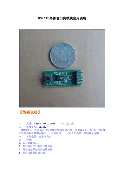
DS1232外部看门狗模块使用说明
【简要说明】
一、尺寸:35mm X15mm X10mm长X宽X高
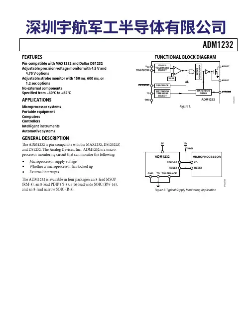
二、主要芯片:DS1232
DS1232是一个具有看门狗功能的电源监测芯片,在电源上电、断电、电压瞬态下降和死机时都会输出一个复位脉冲,十分适合作为单片机的复位电路。
三、工作电压:直流5伏;
四、特点:
1、具有电源指示。
2、具有高电平有效复位输出端
4、具有高电平有效复位输出端
5、具有按钮复位输入端
6、精确的10%电源供电监视;
7、输入给看门狗的脉冲的时间间隔小于1.2S
8、具有看门狗功能,可以防止单片机系统死机;
9、芯片内含温度补偿电路
五、有详细使用说明书
适用场合:单片机学习、电子竞赛、产品开发、毕业设计。
【标注图片】
【原理图】产品淘宝有售
【PCB尺寸图】
【产品展示】。
SmartFusion2 MSS Watchdog Timer ConfigurationSmartFusion2 MSS Watchdog Timer Configuration Table of ContentsConfiguration Options . . . . . . . . . . . . . . . . . . . . . . . . . . . . . . . . . . . . . . . . . . . . . . . . . . . . . . . . . . . . . . 3 Configuration Options . . . . . . . . . . . . . . . . . . . . . . . . . . . . . . . . . . . . . . . . . . . . . . . . . . . . . . . . . . . . . . . . . . . . . . . 3A Product Support. . . . . . . . . . . . . . . . . . . . . . . . . . . . . . . . . . . . . . . . . . . . . . . . . . . . . . . . . . . . . . . . . . . 5Customer Service . . . . . . . . . . . . . . . . . . . . . . . . . . . . . . . . . . . . . . . . . . . . . . . . . . . . . . . . . . . . . . . . . . . . . . . . . . 5 Customer Technical Support Center . . . . . . . . . . . . . . . . . . . . . . . . . . . . . . . . . . . . . . . . . . . . . . . . . . . . . . . . . . . . 5 Technical Support . . . . . . . . . . . . . . . . . . . . . . . . . . . . . . . . . . . . . . . . . . . . . . . . . . . . . . . . . . . . . . . . . . . . . . . . . . 5 Website . . . . . . . . . . . . . . . . . . . . . . . . . . . . . . . . . . . . . . . . . . . . . . . . . . . . . . . . . . . . . . . . . . . . . . . . . . . . . . . . . . 5 Contacting the Customer Technical Support Center . . . . . . . . . . . . . . . . . . . . . . . . . . . . . . . . . . . . . . . . . . . . . . . . 5 ITAR Technical Support . . . . . . . . . . . . . . . . . . . . . . . . . . . . . . . . . . . . . . . . . . . . . . . . . . . . . . . . . . . . . . . . . . . . . . 6Configuration OptionsThe Watchdog Timer is an Advanced Peripheral Bus (APB) slave that guards against system crashes by requiring that it is regularly serviced by the ARM® Cortex™-M3 microcontroller or by a bus master in the field programmable gate array (FPGA) fabric. For complete details please refer to the MicrosemiSmartFusion2 User's Guide.Configuration OptionsEnabling/Disabling the watchdog - The Watchdog Timer can be enabled or disabled by using Flash Bits or by using the ARM® Cortex™-M3 microcontroller firmware. Once disabled, the Watchdog Timer can only be re-enabled as a result of a power-up reset. On the MSS canvas, you can enable/disable the watchdog instance (Figure 1).Timeout - A control bit in the WDOGCONTROL register is used to determine whether the Watchdog Timer generates a reset or an interrupt, if a counter timeout occurs (Figure 2). The default setting is reset generation on timeout. When interrupt generation is selected, the WDOGTIMEOUTINT output isasserted on timeout and remains asserted until the interrupt is cleared. When reset generation is selected, the Watchdog Timer does not directly generate the system reset signal. Instead, when the counter reaches zero, the Watchdog Timer generates a pulse on the WD_TIMEOUT output and this is routed to the reset controller to cause it to assert the necessary reset signals.The pulse on the WD_TIMEOUT output is generated in the RCOSCCLK domain and has duration of one clock cycle. Use the Timeout behavior option to set the WDOGCONTROL register value loaded (Flash Bits) at POR and/or when the device is reset (DEVRST_N is asserted/de-asserted).Interrupt Port - If the Timeout behavior option has been set to Interrupt (Figure 2) you can expose the WD_TIMOUT port the FPGA fabric by checking the Expose WD_TIMEOUT port to Fabric check box.Refresh Count - The WDOGLOAD register is used to store the value that is loaded into the counter each time the Watchdog Timer is refreshed (Figure 3). The six least significant bits of the WDOGLOAD register are always set to 0x3F, irrespective of what value is written to it. This effectively means that there is a lower limit on the value that can be written to the counter. Use the Refresh Count option to set theFigure 1 • Disabled WatchdogFigure 2 •Timeout ConfigurationWDOGLOAD register value loaded (Flash Bits) at POR and/or when the device is reset (DEVRST_N is asserted/de-asserted).Counter Threshold - The Watchdog Timer counter is refreshed by writing the value 0xAC15DE42 to the WDOGREFRESH register (Figure 4). This causes the counter to be loaded with the value in theWDOGLOAD. An appropriate value must be written to the WDOGLOAD System register before writing to the WDOGREFRESH register. Forbidden and permitted windows in time regulate when refreshing can occur.The size of these windows is controlled by the value in the WDOGMVRP System register. When the counter value is greater than the value in the WDOGMVRP , refreshing the Watchdog Timer is forbidden. If a refresh is executed in these circumstances, the refresh is successful, but a reset or interrupt(depending on Operation mode selected) is also generated. When the counter value falls below the level programmed in the WDOGMVRP , refreshing of the Watchdog Timer is permitted.It is possible to avoid having forbidden and permitted windows by ensuring that the value in theWDOGMVRP is greater than the value in the WDOGLOAD. Use the Refresh Count option to set the WDOGLOAD register value loaded (Flash Bits) at POR and/or when the device is reset (DEVRST_N is asserted/de-asserted).Figure 3 • Refresh Count ConfigurationFigure 4 •Counter Threshold ConfigurationA – Product SupportMicrosemi SoC Products Group backs its products with various support services, including CustomerService, Customer Technical Support Center, a website, electronic mail, and worldwide sales offices.This appendix contains information about contacting Microsemi SoC Products Group and using thesesupport services.Customer ServiceContact Customer Service for non-technical product support, such as product pricing, product upgrades,update information, order status, and authorization.From North America, call 800.262.1060From the rest of the world, call 650.318.4460Fax, from anywhere in the world, 408.643.6913Customer Technical Support CenterMicrosemi SoC Products Group staffs its Customer Technical Support Center with highly skilledengineers who can help answer your hardware, software, and design questions about Microsemi SoCProducts. The Customer Technical Support Center spends a great deal of time creating applicationnotes, answers to common design cycle questions, documentation of known issues, and various FAQs.So, before you contact us, please visit our online resources. It is very likely we have already answeredyour questions.Technical SupportVisit the Customer Support website (/soc/support/search/default.aspx) for moreinformation and support. Many answers available on the searchable web resource include diagrams,illustrations, and links to other resources on the website.WebsiteYou can browse a variety of technical and non-technical information on the SoC home page, at/soc.Contacting the Customer Technical Support CenterHighly skilled engineers staff the Technical Support Center. The Technical Support Center can becontacted by email or through the Microsemi SoC Products Group website.EmailYou can communicate your technical questions to our email address and receive answers back by email,fax, or phone. Also, if you have design problems, you can email your design files to receive assistance.We constantly monitor the email account throughout the day. When sending your request to us, pleasebe sure to include your full name, company name, and your contact information for efficient processing ofyour request.The technical support email address is **********************.© 2012 Microsemi Corporation. All rights reserved. Microsemi and the Microsemi logo are trademarks of Microsemi Corporation. All other trademarks and service marks are the property of their respective owners.Microsemi Corporation (NASDAQ: MSCC) offers a comprehensive portfolio of semiconductor solutions for: aerospace, defense and security; enterprise and communications; and industrial and alternative energy markets. Products include high-performance, high-reliability analog and RF devices, mixed signal and RF integrated circuits, customizable SoCs, FPGAs, and complete subsystems. Microsemi is headquartered in Aliso Viejo, Calif. Learn more at .Microsemi Corporate HeadquartersOne Enterprise, Aliso Viejo CA 92656 USAWithin the USA: +1 (949) 380-6100Sales: +1 (949) 380-6136Fax: +1 (949) 215-4996My CasesMicrosemi SoC Products Group customers may submit and track technical cases online by going to My Cases .Outside the U.S.Customers needing assistance outside the US time zones can either contact technical support via email (**********************) or contact a local sales office. Sales office listings can be found at /soc/company/contact/default.aspx.ITAR Technical SupportFor technical support on RH and RT FPGAs that are regulated by International Traffic in Arms Regulations (ITAR), contact us via ***************************. Alternatively, within My Cases , select Yes in the ITAR drop-down list. For a complete list of ITAR-regulated Microsemi FPGAs, visit the I TAR web page.。

看门狗芯⽚MAX708的⼯作原理及数据保护系统设计MAX708是⼀种微处理器电源监控和看门狗芯⽚,可同时输出⾼电平有效和低电平有效的复位信号。
复位信号可由VCC电压、⼿动复位输⼊,或由独⽴的⽐较器触发。
域值为1.25 V、⽤于电源失效或低电源警告的独⽴⽐较器可⽤于监视第2个电源信号,为处理器提供电压跌落的预警功能。
这⼀功能是为器件发出复位信号前的正常关机、向操作者发送警报或电源切换及数据保护⽽考虑的。
MAX708提供有3种复位域值电平可供选择,这3种域值为:2.63 V、2.93 V、3.08 V。
同时提供⼿动复位输⼊信号,在VCC=1 V时能提供有效的RESET复位信号。
MAX708内部由上电⽐较器、复位信号发⽣器、反相器以及失电⽐较器组成。
它们的引脚及功能分别说明如下。
引脚1:MR,⼿动复位输⼊。
当MR输⼈信号低于0.8 V时,产⽣复位脉冲信号输出。
当MR输⼊低电平时,会有250µA的内部拉出电流,该拉出电流可以驱动连接在MR端的TTL或CMOS逻辑门,也可以由开关短路到地。
⼀般在MR输⼊的⼿动复位信号由开关或逻辑门产⽣,这时,⼿动开关应接到地,或逻辑门应输出低电平。
所以,MAX708内部拉出电流会作为外部逻辑门的灌⼊电流,或开关短路到地的电流。
引脚2:VCC,+5 V电源。
引脚3:GND,信号地。
引脚4:PFI,电源电压下降监视输⼊端。
当PFI端输⼊低于1.25 V时,就会使PFO端输出低电平。
如果PFI端不⽤时,把其接到GND或VCC端。
引脚5:PFO,电源电压下降监视输出端。
当PFI端输⼊低于1.25 V时,就会使PFO端输出低电平,同时接收灌⼊电流,其他状态PFO输出⾼电平。
引脚6:空脚,不⽤。
引脚7:RESET,低电平复位输出脉冲端,脉冲宽度为200 ms。
如果电源VCC低于复位门槛4.65 V时,则保持输出低电平⽽不是脉冲。
接通VCC时,由于VCC从0→5V,故会产⽣200 ms的复位脉冲输出。
带看门狗喂狗功能的TMS320F2812远程加载技术蒋炯炜;雷志军;于鹏【摘要】为了提高系统可靠性,外部硬件看门狗电路的应用越来越广泛,但多数情况下,更新程序的同时无法完成喂狗操作,致使芯片不断复位,无法完成软件升级.在此基础上提出了一种基于RS232的带喂狗功能的TMS320F2812程序的远程加载方案,并详细阐述了实现过程.该方案不仅摆脱了Flash编程时对JTAG接口的依赖,而且对底层Flash API函数进行了修改,加入了喂狗程序,灵活性高,非常适用于军用领域,具有较大的实用价值.【期刊名称】《电子与封装》【年(卷),期】2016(016)010【总页数】4页(P23-26)【关键词】F2812;RS232;看门狗;远程更新【作者】蒋炯炜;雷志军;于鹏【作者单位】中国电子科技集团公司第58研究所,江苏无锡214072;中国电子科技集团公司第58研究所,江苏无锡214072;中国电子科技集团公司第58研究所,江苏无锡214072【正文语种】中文【中图分类】TN402随着科学技术的进步,系统的可靠性越来越受到重视,特别是军用领域的要求更苛刻。
看门狗电路就是提高系统可靠性的一种关键技术,在出现死机、程序跑飞、程序有BUG导致不受控等情况出现时,可以起到复位系统的作用。
看门狗电路分为内部看门狗(集成在处理器内部)和外部看门狗(基于硬件)。
内部看门狗便于设计但容易失效,在程序运行失效时会禁止看门狗,导致系统的进一步混乱。
而外部看门狗虽然需要占用额外的电路板空间,但其不仅可以监测VCC电源,在电压跌落到指定的门限以下时触发系统复位,而且完全不受内部程序失效的影响,对于可靠性要求较高的设计是不可或缺的。
在大多数控制场合两者互相配合一起使用。
在系统可靠性提高的同时也带来一个新的问题。
由于大多数自动化设备安装在野外或整机内部,若已安装的设备出现程序缺陷或用户提出新的需求,就需要对程序进行远程更新。
以F2812为例,更新Flash程序的过程是个先擦后写的步骤。
目录摘要: (1)第一章抽油烟机的方案设计 (3)§1.1 吸油烟机的两种设计方案 (3)§1.2 方案比较 (4)§1.3 方案概述 (4)第二章各检测电路设计 (6)§2.1电源电路 (6)§2.2 煤气检测 (6)§2.3 油烟蒸汽检测 (7)§2.4 按键输入 (8)§2.4.1 按键说明 (8)§2.4.2 按键接口电路 (9)§2.5 系统自动复位电路 (10)第三章主控制电路设计 (11)§3.1 单片机最小系统 (11)§3.2 抽油烟机的开关控制电路 (11)§3.3 自动照明控制 (12)§3.4 定时显示电路 (13)§3.5 报警电路 (14)第四章程序设计 (15)§4.1 主程序的设计 (15)§4.2 中断键盘扫描 (16)§4.3 显示子程序 (17)§4.4 INTI中断报警服务程序 (17)参考文献 (18)智能油烟机控制电路摘要:智能油烟机控制电路不仅具有油烟机基本的开关功能,而且还能根据厨房在烧菜做饭的过程中产生的油烟温度高,而泄漏的燃气温度低的特点,采取不同的传感器件进行检测。
当厨房的油烟或可燃有害气体达到一定浓度的值时,经传感器进入单片机的分析,使电机电路自动启动并发出声音报警,吸油烟机迅速将有害气体抽走。
本设计还设有定时功能,可对抽油烟机进行时长的设定。
论文的硬件部分主要设计了油烟机的烟气、燃气检测模块,按键输入模块,显示模块,执行电路模块等。
智能油烟机控制电路主要靠单片机进行控制,通过软件设计来自动控制油烟机的开关,所以具有自动检测和智能控制的功能。
关键词:AT89C51 MQ-5 DS1232Intelligent Hood Control CircuitAbstract: Intelligent Hood Control Circuit not only has lampblack machinebasic switch function, and still can according to the kitchen is in the process of cooking oil produced in high temperature, the gas leak of low temperature characteristic, take different sensors detect thing. When the kitchen lampblack or flammable harmful gas reaches a certain concentration of value, the sensor into SCM analysis, make motor circuit automatically start and sound alarms, oil absorption rapidly take the harmful gas siphoned off. This design also is equipped with timing function, may to the smoke lampblack machine when carried out long setting. The paper mainly designed hardware components of smoke lampblack machine, gas detection module, key input module, timing display module, executive circuit module, etc. Intelligent Hood Control Circuit controlled mainly by MCU, through software designed to automatic control lampblack machine switches, so has the automatic detection and intelligent control function.Key Words:AT89C51,MQ-5,DS1232第一章抽油烟机的方案设计在现代电子技术领域中,实现抽油烟机的控制电路的方法多种多样,可以通过纯硬件电路来实现,也可以采用硬件和软件结合的电路来完成。
DS1232 看门狗芯片
●结构及特点
DS1232是一个具有看门狗功能的电源监测芯片,在电源上电、断电、电压瞬态下降和死机时都会输出一个复位脉冲
⊙具有看门狗功能,可以防止单片机系统死机;
⊙输入给看门狗的脉冲的时间间隔可以设置;
⊙具有5%或10%的两种电源监测精度(芯片内含温度补偿电路)。
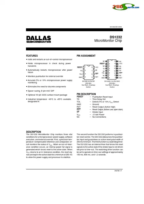
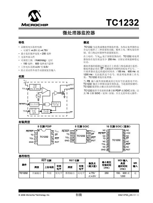
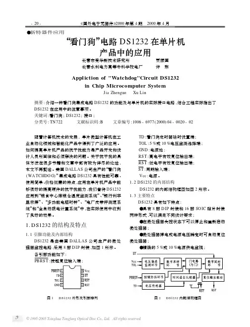
RESTE ——复位键连接引脚,直接连接复位键。
TD ——看门狗定时器延时设置。
如果连接到地,输入给看门狗的脉冲间隔不得大于150毫秒;如果不连接,脉冲间隔不得大于600毫秒;如果连接到电源,脉冲间隔不得大于1.2秒。
TOL ——选择5%或10%的电源监测精度。
如果这个引脚连接到地,当电源下降到4.75V时芯片将输出一个复位脉冲;如果这个引脚连接到5V,只有当电源下降到4.5V时芯片才输出一个复位脉冲。
GND ——地线。
RST ——复位高脉冲输出引脚。
RST/ ——复位低脉冲输出引脚.
ST/ ——看门狗脉冲输入,低脉冲有效。
VCC ——5V电源。
芯片DS1232在系统工作时,必须不间断的给引脚7输入一个脉冲系列,这个脉冲的时间间隔由引脚2设定,如果脉冲间隔大于引脚2的设定值,芯片将输出一个复位脉冲使单片机复位。
一般将这个功能称为看门狗,将输入给看门狗的一系列脉冲称为“喂狗”。
这个功能可以防止单片机系统死机。
●DS1232的应用电路
DS1232的应用原理图,其中TD连接到5V电源,因此输入给看门狗的脉冲间隔不可以超过1.2秒;TOL 连接到地,因此电源电压下降到4.75V时就会引起DS1232输出复位脉冲;图中使用一个复位键;把51单片机的P1.1引脚连接到,因此在程序中必须从P1.1引脚输出一个脉冲系列,否则将引起系系统复位。
注意:(1)ST除了和单片机的ALE相连外还可以和其他信号相连,但必须保证在看门狗定时计数溢出前复位看门狗定时器。
(2)DS1232的6脚没有上拉电阻,如果其他外围芯片需要用到低电平复位信号,那么必须在引脚上外接上拉电阻。
(3)如果仿真器用户连接调试板,并且ST和ALE相连,最好先不要插上DS1232芯片,因为单步是ALE脚的并不是连续供给的,容易造成非正常复位。