HY500配料控制器使用说明书调试手册u
- 格式:doc
- 大小:113.00 KB
- 文档页数:12

1使用说明书2信道可编程温度控制器非常感谢您购买(株)韩荣电子有限公司的产品。
请阅读使用说明书后按照说明使用。
为方便于今后使用本产品,请务必保管好此说明书。
声明此使用说明书受版权保护,并拥有与此相关的所有权利。
在未得到(株)韩荣电子有限公司的事前书面承认时,不允许对此文件的任何部分进行复印、再生、改造或翻译成其它语言。
此使用说明书的内容以“现状”被提供后,可能会在没有事前通知的情况下进行变更。
关于此说明书,除了对此产品的默认保障或特定目的外,(株)韩荣电子有限公司不作任何保障。
包含在此产品中的程序受版权保护。
在未得到(株)韩荣电子有限公司的事前书面承认时,禁止对此程序进行再生、改造、翻译。
使用于此文件及产品上的其它所有品名是该所有者的称号、服务标记、商标或注册商标。
(株)韩荣电子有限公司本社地址402-205仁川广域市南区朱安洞1381-3TEL:(032)867-0941(代表电话)FAX:(032)868-5899目录1.使用之前 1.1 产品的确认 51.2 安全注意事项 62.安装方法 2.1 安装场所及注意事项 72.2 安装方法 82.3 型号名称 92.4 外形/面板加工尺寸及接线图 92.5 接线方法 113.操作及设定 3.1 初始画面 153.2 基本输入方法 153.3 运转画面各部分名称 173.4 定值控制运转 263.5 程序控制运转 273.6 曲线图显示及设定 303.7 故障及各种事件明细 314.画面构成 4.1 运转画面 324.2 设定画面 345.功能设定 5.1 运转设定 355.2 时间/预约设定 365.3 程序设定 366.系统设定 6.1 传感器输入设定 406.2 控制/传送输出设定 416.3 内部信号设定 426.4 警报设定 436.5 PID设定 436.6 接点输入(D.I)构成设定 456.7 接点输出(D.O)构成设定 466.8 通信设定 486.9 其它设定 487.式样 7.1 输入式样 497.2 输出式样 497.3 功能式样 507.4 通信式样 517.5 电源式样 517.6 动作环境 527.7 输送/保管条件 52非常感谢您购买(株)韩荣电子有限公司的恒温、恒湿程序控制器(型号:TD500)。
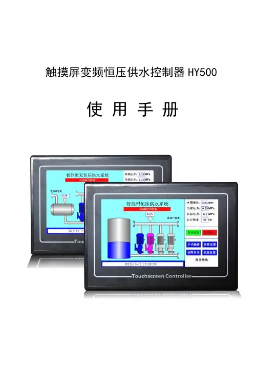
触摸屏变频恒压供水控制器HY500 使用手册感谢您选用触摸屏变频恒压供水控制器。
为充分发挥本产品的卓越性能及确保使用者和设备的安全,在使用之前,请详细阅读本手册。
一、系统概述第二代变频恒压供水控制器,专业为供水行业打造的高档人机界面控制器。
产品投入市场以来,深受新老客户喜爱。
该控制器可安全稳定运行于各种环境,几千台覆盖全国范围的使用,几乎零故障率。
相比第一代,人机界面更加友好,功能更加完备,性能更加稳定。
具有压力控制精度高、稳定性好,全自动7段时间压力控制及定时启停水泵。
远程启动第二压力,能很好地满足消防供水需求。
第二代变频恒压供水控制器采用7寸高清彩色液晶屏,触摸操作,全中文界面显示,所见即所得。
系统采用智能自适应PID调整,方便用户调试使用。
直观的人机界面带给你操作方便;工业级的元件,使产品经久耐用、运行稳定可靠、抗干扰能力强;独特完备的接口设计,能满足您不同的现场需求。
产品提供完备的输入输出信号,可与各种品牌的变频器配套使用。
另有市政压力或水箱液位等信号供使用。
可方便地切换控制器为水箱恒压供水或无负压供水。
可适应远传压力表和压力变送器信号。
并有RS485通讯接口与上位机服务器连接,实现远程控制和查询供水系统。
在用户的使用上,无需编程,只需有普通电工知识,依照我公司提供的原理图接线,简单设置后即可使您的供水系统正常投入使用。
高档的产品、极具竟争力的价格、稳定的质量和完善的售后服务是公司一贯的坚持。
目录一、系统概述 (2)二、控制器的安装 (4)三、注意事项 (5)四、功能特点 (6)五、技术指标 (7)六、接线端子图 (8)七、接线端子说明 (9)八、端子与部分变频器端子的连接表 (10)九、连接ABB变频器参数设置 (10)十、主界面与操作说明 (11)十一、参数设置界面说明 (16)十二、系统设置界面说明 (23)十三、电气原理图 (27)十四、RS485通讯协议 (30)十五、变频恒压供水控制器联网示意图 (33)十六、常见故障处理 (34)十七、部分客户名录 (35)十八、品质保证 (36)二、控制器的安装1、控制器外形尺寸:210mm*150mm*50mm;2、控制柜安装开孔尺寸:177mm*128mm;3、控制器安装:安装时在控制柜前面板开一方孔(开孔尺寸:177mm*128mm),将控制器端子排拔下后镶嵌于前面板上,用随机的卡子固定,插上端子排,然后接线即可。

555 Hotplate 565 Magnetic Stirrer 575 Hotplate-StirrerC ONTROL P ANELThe front panel of the Series 500 hotplate/stirrer/hotplate-stirrer contain all switches, controls and displays needed to operate the unit.Rocker switch:Press left side to turn power on, right side to shut off power.Time display:Shows how long the unit has been heating (continuous mode) or how much time is left to heat (timed mode). The display range is from 0 to 9,999 minutes in one second increments.Speed display:Shows the speed of the stirrer. up/down arrows for setpoint control. On/Off button starts/stops stirring feature. Speed range is from 60 to 2000rpmTemperature display:Shows the actual/setpoint temperatures, up/down arrows for setpoint control, On/Off button starts/stops the heating feature. Plate indicator light:Lights when the external temperature probe is not being used. The actual temperature displayed is the top-plate temperature.Probe indicator light:Lights when the external temperature probe is plugged in. The actual temperature displayed is the probe temperature, not the top-plate temperature.Actual indicator light:Lights when the temperature displayed is the actual temperature of the top-plate/temperature probe.Setpoint indicator light:Lights when the setpoint temperature is displayed.Plate hot indicator light:Lights when the top-plate temperature is above 40oC.2I NSTALLATIONAfter unpacking, place your VWR Series 500 microprocessor-controlled hotplate/stirrer/hotplate-stirrer on a level bench or table, away from explosive vapors. Be sure the unit is well clear of papers, drapery and curtains, and other flammable materials.The 120v and 230v units are supplied with a 3-prong power cord that should be plugged into a standard 3-prong grounded outlet.PLEASE NOTE: If you observed any damage to the carton or now see any shipping damage to the unit, contact the carrier immediately to file a claim.Caution!Keep the unit away from explosive vapors, and clear of papers, drapery, curtains, and other flammable materials.C AUTION ! Do not operate the unit at high temperature without a vessel on the top plate.C AUTION ! Always operate the unit on a level surface for best performance and maximum safety.C AUTION ! Keep the electrical cord away from the heater plateW ARNING!Do not use the Series 500 hotplate/stirrer/hotplate-stirrers in a hazardous atmosphere or with hazardous materials.Also, the usershould be aware that the protection provided by the equipment might be impaired if used with accessories not provided or recommended bymanufacturer, or used in a manner not specified by the manufacturer .ƽƽƽᏘƹƽ3555 Hotplate5Plate indicatorlightActual indicatorlight Probe indicatorlightSet point indicator light Temperature displayOn/Off buttonTime displayPower switchPlate hotindicator light565 Magnetic Stirrer7Time displaySpeed displaySpeedOn/Off keypadPower switch89Specifications:Catalog No:14217-604 - 120v 14217-610 - 230vDimensions:W x H x D8-1/4" x 5" x 12"(20.96cm x 12.7cm x 30.48)W eight Capacity: 25 lbs Top plate:Ceramic 7 x 7Voltage:120v/230v Current:120v - 7 amps230v - 4 ampsFuses:120v - 5mm x 20mm, 10 amp quick acting230v - 5mm x 20mm, 5 amp quick actingPower:800 watts Speed:60 to 2000rpmTemp. Accuracy:+/- 3% at 400o C w/temperature probe+/- 1% below 100o C w/temperature probeControls: 2 way rocker switchTimer:Digital, LED, 1 second to 9999 minutes (increased in 1 second increments)Up/Down Keypad for setpoint control Speed: 60 to 2000rpm Digital, LED,Up/Down keypad for setpoint control On/Off buttonTemperature:ambient to 400o C Digital, LED,Up/Down Keypad for setpoint control On/Off buttonShip weight:10.5 lbs. (5kg)575 Hotplate StirrerPlate indicatorlight Actual indicatorlightProbe indicatorlightSet point indicator lightTemperature displayTemperature On/Off buttonPower switchSpeed displayTime displaySpeedOn/Off buttonPlate hot indicator lightM:q qPhone: 856-686-1600 q Fax: 856-686-1601 q email:*********************586050-00 4-047-INS Rev (1/03)。

配料机使用说明书目录1.简介和快速入门 (1)2.控制器面板及按键说明技术规格 (6)3.校称操作 (10)4.配方管理 (13)5.配置参数管理 (17)6.落差管理 (25)7.自动配料操作 (27)8.维护调试与常见问题 (33)9.控制器后面板说明与接线 (38)10.功能特点和技术规格 (43)11.售后服务和联系方式 (47)简介和快速入门本章用于帮助用户快速入门,详细说明请参考后面章节。
1.简介YT1200C配料控制器是专为建筑机械中各种配料系统设计。
该控制器采用了工业级微处理器和24位高精度A/D转换芯片设计,全数字处理技术。
整机设计先进,功能强大。
具有以下主要特点:测量精度高,配料准确控制4路上料,2路卸料(或者5路上料,1路卸料)永久储存九种配方,掉电不丢数据全数字式校准和设定,操作简单易用,准确可靠。
具有输入输出自检功能,并能够检测传感器故障,特别易于维护。
特别设计的过压过流和防雷保护,保障仪表适应工地恶劣环境,可靠工作。
操作简单,抗干扰能力强,各种状态数据自动保存,工地电源不稳定或突然断电也能正常运行,不丢数据,不用维护,可靠耐用。
2.状态说明YT1200C配料控制器分为“手动”和“自动”两个基本状态,“手动”状态用于各项参数设置。
“自动”状态下,控制器按照配方执行自动配料工作。
两种状态通过控制器面板上按键切换,或按遥控盒的“启停”按钮切换。
“手动”状态的显示:状态标志显示字母“C”表示当前是手动称重状态。
该处在设定配方时显示“PF”,校准时显示“JF”,设置参数时显示“F”,查看落差时显示“L”。
第二行显示当前使用的配方信息,滚动显示该配方对应的四种物料的用量定值。
“自动”状态的显示:显示窗的第一行显示已配制罐数,和称量斗的当前称重值。
(在“自动”状态下可以按“复零”键将配制罐数清零)。
第二行上料时显示使用的配方序号,当前正在上料的物料序号,和当前该物料的实际用量。
如果是卸料,第二行则显示配方号和卸料方向。
尤尼帕斯称重配料显示控制器安全操作及保养规程尤尼帕斯(Unipulse)称重配料显示控制器是一种高性能电子称重设备,可广泛应用于各种工业生产场合,例如化工企业、粮食加工企业、医药制造企业等。
为了保障其安全、高效的使用,需要遵守一定的安全操作规程和保养维护措施。
本文将介绍尤尼帕斯称重配料显示控制器的安全操作及保养规程。
一、安全操作规程1.1 使用前的检查在使用尤尼帕斯称重配料显示控制器前,需要进行以下检查:•检查所有电缆是否齐全、无损坏、连接正确;•检查传感器是否良好、轴承是否灵活,并检查传感器连接处是否固定;•检查电气设备是否接地可靠;•确保称重平台的支架稳固并水平。
1.2 操作前的准备在使用尤尼帕斯称重配料显示控制器前,需要进行以下操作准备:•将所有松动的螺丝紧固,确保设备处于完整的状态;•操作前清理产品残渣并清理称重平台;•正确设置设备的参数,包括产品容量、控制参数等;•确定设备安全工作状态,包括限制保护功能、报警功能等。
1.3 操作安全规程在使用尤尼帕斯称重配料显示控制器时,需要遵守以下安全规程:•严禁在不了解说明书的情况下以及未获得厂家认可的情况下进行任何的修改或设备改装;•在操作过程中,严禁让机器运行在超负荷的情况下;•如果发现设备出现任何异常情况,及时停止其工作并通知专业人员进行检查;•防止进入设备内部进行检查保养,除非经认证的专业人员。
1.4 关机前的操作在使用尤尼帕斯称重配料显示控制器完成工作后,需要进行以下操作:•关闭设备及外部电源;•清理称重平台以及检查设备是否存在异常情况;•将设备及其附件妥善存放,确保设备处于良好的状态。
二、保养维护规程2.1 日常清洁维护尤尼帕斯称重配料显示控制器需要进行定期清洁,清洁方法如下:•使用软布或刷子清理配料平台上的杂质;•使用干净的湿布擦拭设备外表面以及显示器;•定期检查电缆连接处是否有松动,是否有裂纹或受损等。
2.2 定期检查维护除了日常清洁维护之外,还需要定期检查维护设备,主要包括以下内容:•对设备内部进行定期检查,检查传感器、电缆等的状况;•检查控制器的输出稳定性和准确性;•对设备进行校准和调整。
调试手册一、简介HY500配料控制器秉承更好更高的设计原则,采用大规模集成电路及高可靠器件,全数字化设计,非常适合建筑行业单配料机的自动生产控制。
具有操作简单方便、质量稳定可靠、控制精度高、价格合理等特点。
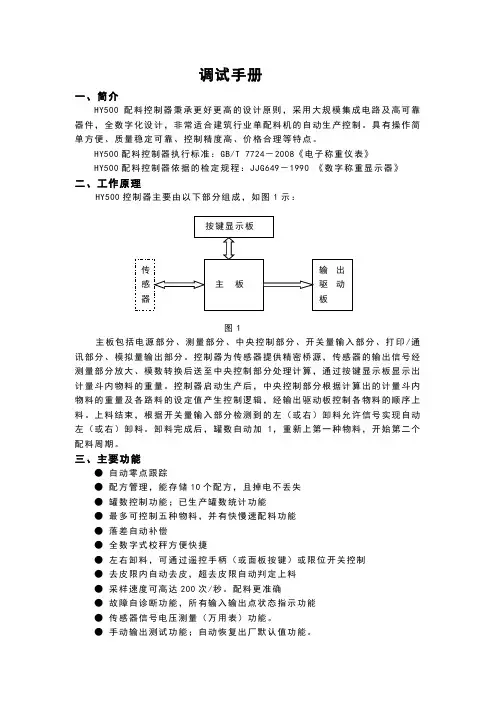
HY500配料控制器执行标准:GB/T 7724-2008《电子称重仪表》HY500配料控制器依据的检定规程:JJG649-1990 《数字称重显示器》二、工作原理HY500控制器主要由以下部分组成,如图1示:图1主板包括电源部分、测量部分、中央控制部分、开关量输入部分、打印/通讯部分、模拟量输出部分。
控制器为传感器提供精密桥源,传感器的输出信号经测量部分放大、模数转换后送至中央控制部分处理计算,通过按键显示板显示出计量斗内物料的重量。
控制器启动生产后,中央控制部分根据计算出的计量斗内物料的重量及各路料的设定值产生控制逻辑,经输出驱动板控制各物料的顺序上料。
上料结束,根据开关量输入部分检测到的左(或右)卸料允许信号实现自动左(或右)卸料。
卸料完成后,罐数自动加1,重新上第一种物料,开始第二个配料周期。
三、主要功能●自动零点跟踪●配方管理,能存储10个配方,且掉电不丢失●罐数控制功能;已生产罐数统计功能●最多可控制五种物料,并有快慢速配料功能●落差自动补偿●全数字式校秤方便快捷●左右卸料,可通过遥控手柄(或面板按键)或限位开关控制●去皮限内自动去皮,超去皮限自动判定上料●采样速度可高达200次/秒。
配料更准确●故障自诊断功能,所有输入输出点状态指示功能●传感器信号电压测量(万用表)功能。
●手动输出测试功能;自动恢复出厂默认值功能。
●通讯功能:标准的RS232或R485输出接口●打印功能,可带标准打印机或微型打印机●模拟输出接口,电流输出范围:4~20mA四、技术参数1、电源:交流220V±10%15%;50Hz±2%2、工作环境温度:0~40℃3、工作环境湿度:≤85%RH,无凝露4、桥源:5V±5%,最大负载能力200mA5、模拟量输入范围:0~18mV6、开关量输出触点容量:≤5A7、开关量输出触点电压:≤交流250V或直流24V8、最大显示:80009、控制器机壳外形尺寸:192mm×96mm×150mm(宽×高×深)10、电气控制柜开孔尺寸: 186+1mm×92+1mm(宽×高)五、前面板说明外观如图2示图2 前面板外观图(一)显示部分说明:1、配方号窗口待机态和运行态显示选用的配方号。
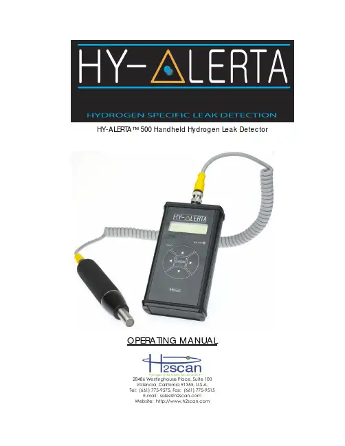
HY-ALERTA™ 500 Handheld Hydrogen Leak DetectorOPERATING MANUAL28486 Westinghouse Place, Suite 100Valencia, California 91355, U.S.A.Tel: (661) 775-9575, Fax: (661) 775-9515E-mail:****************Website: MISSION STATEMENTTo become the leading provider of hydrogen specific safety monitoring and in-line process measurement systems where hydrogen gas is produced, used, consumed, stored and transported.We are committed to providing cost-effective solutions as new installations and replacements for existing hydrogen gas analyzers to OEM customers and through our global distribution network.Our products will achieve worldwide recognition in industrial safety and process applications based on superior products, while maintaining excellent relationships with and ensuring unsurpassed value to our business partners around the globe.CONTENTS1. Description (5)2. Specifications (5)3. Operation (7)3.1 Startup (7)3.2 Shutdown (7)3.3 Battery Level (7)3.4 Normal Operation (7)3.5 Hydrogen-Free Areas (10)3.6 Reset Operation (10)3.7 Zero Operation (10)4. Keypad (11)4.1 Numerical Changes (11)4.2 Top Level Keypad Functions (11)4.3 General Keypad Functions (Also See Section 10) (11)4.4 Information Display (11)4.5 Firmware Rev: (11)4.6 Serial Number: (11)4.7 Calibration Date: (12)4.8 Reset Sensor (12)4.9 Zero Sensor (12)4.10 Verify (12)5. Hydrogen Sensing Considerations (13)6. Bump Test (14)7. Verification (14)7.1 Gases (14)7.2 Gas Connection (14)7.3 Verification Kits (14)8. Battery Charging (16)9. Cleaning (16)10. Troubleshooting (16)11. Menu Structure (17)12. Appendix (21)12.1 European Declaration of Conformity (21)IMPORTANT NOTICESRead and understand this operating manual before installing or using the unit.Only use cables, battery pack, battery charger, and AC/DC power supplyfrom H2scan with this unit.If this equipment is used in a manner not specified by H2scan, the protection provided by this equipment may be impaired.Hydrogen is flammable at 4% in air. Take indications seriously and be prepared to take action. In the event of detection of 4% or higher of a hydrogen gasconcentration there is a high probability of a hazard to safety. Inform localemergency response personnel immediately.LIMITATION OF LIABILITYIn the event of a defect in a product, h2scan shall not be responsible for any direct, indirect, incidental or consequential damages resulting therefrom, including, but not limited to, loss of revenue and/or profit.LIMITED WARRANTYH2scan Limited Warranty: Each hydrogen instrument (“Product”) will conform, as to all substantial operational features, to the Product specifications set forth this Manual and will be free of defects which substantially affect such Product’s performance for twelve (12) months from the ship date for such Product.Must Provide Notice of Defect: If you believe a Product that you believe is defective, you must notify H2scan in writing, within ten (10) days of receipt of such Product, of your claim regarding any such defect.Return Product to H2scan for Repair, Replacement or Credit. If the Product is found defective by H2scan, H2scan’s sole obligation under this warranty is to either (i) repair the Product, (ii) replace the Product, or (iii) issue a credit for the purchase price for such Product, the particular remedy to be determined [by H2scan] on a case-by-case basis.Voided Warranty. H2scan’s 12 Month Limited Warranty is void for any of the following:The unit is opened and the manufacturing seal is brokenUnauthorized repair work performed at the customer’s location or carried out by anyone other than H2scan’s factory trained technicians Equipment or parts that have been tampered with, misused, neglected, mishandled, improperly adjusted, or modified in any way without the written consent of H2scan.Equipment or parts that have been damaged due to shipping, misuse, accidents, mishandling, neglect, or problems with electrical power sources.Repair work performed during the warranty period does not prolong the warranty period past the original period.System operation in incorrect or inappropriate environments.Usage that is not in accordance with system guidelines or an operator’s failure to follow manual instructions.Limitation of Warranty: THE ABOVE IS A LIMITED WARRANTY AS IT IS THE ONLY WARRANTY MADE BY H2SCAN. H2SCAN MAKES NO OTHER WARRANTY EXPRESS OR IMPLIED AND EXPRESSLY EXCLUDES ALL WARRANTIES OF MERCHANTABILITY AND FITNESS FOR A PARTICULAR PURPOSE. YOUR SOLE REMEDY HEREUNDER IS REPAIR OR REPLACEMENT OF THE PRODUCT OR A CREDIT FOR THE PURCHASE PRICE FOR SUCH PRODUCT, THE PARTICULAR REMEDY TO BE DETERMINED BY H2SCAN ON A CASE-BY-CASE BASIS. H2SCAN SHALL HAVE NO LIABILITY WITH RESPECT TO ITS OBLIGATIONS UNDER THIS AGREEMENT FOR CONSEQUENTIAL, EXEMPLARY, OR INCIDENTAL DAMAGES EVEN IF IT HAS BEEN ADVISED OF THE POSSIBILITY OF SUCH DAMAGES. THE STATED EXPRESS WARRANTY IS IN LIEU OF ALL LIABILITIES OR OBLIGATIONS OFH2SCAN FOR DAMAGES ARISING OUT OF OR IN CONNECTION WITH THE DELIVERY, USE OR PERFORMANCE OF THE PRODUCTS.1.DescriptionH2scan believes that protecting lives means being able to locate and findhydrogen leak as quickly as possible. With two sensing elements on the same semiconductor die, the HY-ALERTA™ 500 can detect hydrogen leaks as low as15 ppm and will not saturate or be destroyed when detecting concentrationsof hydrogen up to 100%. The flexible cable allows the sensor probe access to virtually all potential leak sources.2.SpecificationsSensitivity Range: 0.0015% (15 ppm) to 100% hydrogen by volume in air.Response Time: Indication of hydrogen within seconds. Stabilization to final value depends on concentration.Ambient Temperatures: Operating: 0°C to +40 °C Storage: -20°C to +45 °CRelative Humidity: 0-95% non-condensingPower: Internal rechargeable Lithium Ion battery yields over 10 hours of operation and is recharged in 4 hours with included charger. Battery charger input: 100-240VAC, 50-60Hz, 0.6A.Environmental: Indoor/Outdoor UseAltitude up to 2000 meters Pollution degree 2 environmentIngress Protection: IP64 capableCalibration Period: Recommended user Verification/Calibration on a 12 month basis. Weight: 975 g (2.15 lb.) unit and carrying pouch2.2 kg (5 lb.) shipping weight (unit with accessories)Product LifeExpectancy: 10 yearsCertifications:Coiled Cord3.Operation3.1StartupTo power-up the HY-ALERTA™ 500, press and hold the ON/OFF button until the Controller LCD display indicates an operational message.Warning: Only power-up the instrument in a hydrogen-free environment.After power is on, the instrument takes about ten minutes to warm-up. During this time the LCD displays a countdown to completion and the Probe Tip LED is amber. The following operations occur:The Wide Range Sensor® reaches operating temperature.A system self-test is run.Upon successful completion of the above tasks the instrument zeroes itself and automatically switches to normal operation. If an error is detected theinstrument will display an error code (see Section 10).3.2ShutdownTo power-down the HY-ALERTA™ 500, press and hold the ON/OFF button forapproximately two seconds until the Controller LCD display turns off.3.3Battery LevelAfter power-on the BATTERY LED indicates the current battery level (times areapproximate and may vary as the battery ages):Color MeaningGreen more than 60 minutes of operation remainingAmber approximately 15 to 60 minutes of operation remainingRed less than approximately 15 minutes of operation remainingA fully charged battery should last 10 to15 hours, depending on use.There is a small load on the battery when the unit is powered off. This load will discharge the battery of the unit in it’s powered off state in about 6 months.Customers that do not use the device frequently should charge the batteryand perform a bump test with hydrogen gas every one to three months tokeep the battery charged and ready for use.3.4Normal OperationDuring normal operation the instrument is detecting and reporting thehydrogen concentration near the probe tip sensor. Hydrogen readings aredisplayed on the controller LCD and the probe tip LED bar graph array. Note that due to the extreme sensitivity of the sensor, it may take several minutes to return to a near zero (less than 0.001%) reading after exposure to hydrogen. If the instrument does not return to an indication of less than 0.001% after 5minutes in a hydrogen-free environment, then invoke the Reset operation (See Section 3.6).The upper line of the Controller LCD indicates a numerical value or range for the percent hydrogen concentration or peak hydrogen value. The lower line is used to display the hydrogen meter, a logarithmic bar graph ranging from0.001% (10 ppm) to 100% hydrogen by volume. An open box on the bar indicates the last peak value obtained and filled boxes indicate the current value. The following figure describes how to interpret the hydrogen meter:The Probe Tip LED Indicator shows an increase or decrease in hydrogenconcentration. Leak detection is accomplished by watching the Probe Tip LED and the bar graph array and moving the sensor around a potential hydrogen leak.The number of yellow LEDs lit in the Probe LED bar graph array indicates detected hydrogen concentrations in four ranges as noted below:3.5Hydrogen-Free AreasFor the purposes of this document a hydrogen-free area is one with less than5ppm of hydrogen in the air.It may be difficult to find a hydrogen-free area in a facility where hydrogen is used. Nearby rooms, or even the entire building, may not be hydrogen free.To check these areas reset or zero the sensor outside, away from any hydrogen tanks, pipes, or other potential sources. Walk through the facility, watching the sensor. It is surprising how far low levels of hydrogen can spread.If the sensor is zeroed or reset in hydrogen, there will be a negative offset in the readings that could compromise the sensor’s ability to find small leaks.3.6Reset OperationThe Reset Operation is used to speed recovery from hydrogen exposure.It can be invoked from the keypad while in the top menu level (measuring hydrogen) by pressing and holding ◄►(left and right arrow buttons simultaneously) or from the Reset Menu (see Section 4). Once invoked the user is asked to confirm the operation by pressing the ENTER key. Pressing any other key will abort the operation. During Reset the LCD indicates a count down to completion and the Probe tip LED is yellow.3.7Zero OperationThe Zero Operation is used to zero the hydrogen reading if the instrument is reporting low levels (0.001% to 0.01%) of hydrogen when no hydrogen is present. This operation can be invoked from the keypad while in the top menu level (measuring hydrogen) by pressing and holding ◄ (left arrow button) or from the Reset Menu (see Section 4). Once invoked the user is asked to confirm the operation by pressing the ENTER key, pressing any other key will abort the operation.4. Keypad4.1 Numerical ChangesIn the following sections when queried to change a numeric value the ▲ (up arrow) and ▼ (down arrow) keys are used to increment/decrement the value based on the selected digit. If the ones digit is selected the value willincrement/decrement by one (9 increments to 10, 10 decrements to 9). The ◄ (left arrow) and ► (right arrow) keys are used to select another digit. Tochange a value of 0 to 100 first select the hundreds digit then press the ▲ up arrow. Pressing ◄► (the left and right arrows simultaneously) will clear any changes made and restore the previous value. Once the correct value is displayed press the ENTER key to save it. 4.2 Top Level Keypad FunctionsWhile in the hydrogen measurement screen, the keypad has these functions:Key Function ENTER Go to the Information Display menu . ▲ Display the peak hydrogen reading. ▼ Display the current hydrogen concentration. ► Clear the peak hydrogen value. ◄ Zero the sensor (see Section 3.7). ◄► Reset the sensor (see Section 3.6).4.3 General Keypad Functions (Also See Section 11)4.4 Information DisplayThe Information Display menu allows the user to view useful information about the instrument including firmware revisions, serial number, and calibration date. Enter it by can be entered by pressing and holding the ENTER button. 4.5 Firmware Rev:This displays the sensor pod and controller firmware. The left most number preceded by an ‘S’ is the Probe firmware revision. The right most number preceded by a ‘C’ is the Controller firmware revision. For example: S1.23 C2.34 for Probe firmware version 1.23 and Controller firmware version 2.34 4.6 Serial Number:This displays the product serial number. For example: 50123Key Navigation Editing Values Query Answer ENTER Enter submenu Select Value Yes ▲ Previous Menu Increase Value No ▼ Next Menu Decrease Value No ► Enter Submenu Move Cursor Right No ◄ Exit Submenu (Back) Move Cursor Left No ◄► Exit Configuration Undo ChangesNo4.7Calibration Date:This displays the date of last factory calibration, MM/DD/YY. For example: 5/8/06 for 8 May 2006.4.8Reset SensorThe Reset Sensor menu is used to invoke the Reset Operation as described in Section 3.6.4.9Zero SensorThe Zero Sensor menu is used to invoke the Zero Operation as described in Section 3.7.4.10VerifyThe Verify menu shows the date of the last field verify and allows the user to invoke the Verify function in Section 6.5.Hydrogen Sensing ConsiderationsFrom any given source, hydrogen gas disperses rapidly and generally upward due to its very low density compared to air. Understanding this behavior allowsa more effective search for hydrogen leaks.The hydrogen plume from a leak generally spreads in a roughly conical shape that is easily disturbed by environmental conditions. Certain conditions such as pressure, temperature, and leak size may act together to change the shape of the hydrogen plume from a cone to a laser-like beam. This makes finding aleak more difficult.If the sensor element is near (and above) the leak, the concentration will likely be higher but the leak may be difficult to locate. As hydrogen dissipates theconcentration decreases. Generally, greater distances will increase thechance of intercepting the leak stream, but if the sensor is too far away, theresponse may be too weak to detect.When drafts or air currents are present, hydrogen will tend to be dispersed.Testing for hydrogen leaks downwind of the leak area may increase thechance of detecting the leak.If hydrogen is rising in an enclosed building the hot air near the ceiling mayslow the hydrogen’s rise. Thus, sensing hydrogen near ceiling areas with hightemperatures present may not be as effective as at a lower level.Low temperatures can also affect the behavior of hydrogen. Hydrogen stored in a liquid state is at an extremely low temperature. The low temperature ofany escaping hydrogen will be of a higher than normal density and mayinitially move downward. As the hydrogen warms, it will begin to rise upward.When checking for a leak in areas where liquid hydrogen is stored, check both above and below the area of concern.6.Bump TestA bump test is recommended every three months. The purpose of a bump testis to verify that the sensor is active, detecting hydrogen and verifying that the sensor is within the pre-set factory tolerance for accuracy. To performs a bump test perform the following:In a non-hydrogen environment, power on the instrument. Once theinstrument has gone through its standard 10 minute warm-up, use thecalibration cup that accompanies the HY-ALERTA™ Model 500, and apply 2% hydrogen to the probe sensor. Let the 2% hydrogen flow for a minimum of 3-5 minutes. After 3-5 minutes the concentration value registered on the LCDdisplay should read between 1.6% to 2.4%, which is within factory tolerance. If the 2% reading is below 1.6% or above 2.4% the instrument should go through a Verification test as outlined below.7.VerificationVerification is performed in a non-hydrogen environment to confirm that theHY-ALERTA™ Model 500 is operating properly and within the pre-set factorytolerance for calibration. The recommended verification interval is every 12months, or after a 2% bump test has been performed and the indicated values on the LCD display were outside the stated tolerance as outlined in Section 6.If the verification fails, then it should be repeated one more time.The HY-ALERTA Model 500 requires calibration only if it fails the secondverification. It cannot be field calibrated and must be returned to h2Scan for calibration service. An optional NIST traceable certificate is available uponrequest.7.1GasesVerification requires the availability of the following certified gases:2.00% hydrogen by volume in air (20,000 ppm)0.10% hydrogen by volume in air (1000 ppm)Zero grade, hydrogen-free air. Ambient air can be substituted if it ishydrogen-free.7.2Gas ConnectionGases are applied to the unit through the use of the Calibration Cup Assy. (P/N 50000009) available from H2Scan.7.3Verification KitsCustomer-specific Field Verification Kits for the HY-ALERTA™ 500 are available from H2scan.The field verification function allows the user to check the instrument’s calibration. Details on this function can be found in Table 1 on page 19. If the unit passes verification, calibration is not required at this time.If the unit fails verification, the unit should be returned to the factory for calibration.8.Battery ChargingEnsure the unit is powered OFF.Disconnect the coiled cord from the controller.Connect the battery charger to the controller.Using the appropriate A/C plug adapter for the region of use, plug the battery charger into the A/C supply.The battery charger indicator light will illuminate according to charge status as follows:Off No BatteryFlashing Green Fast chargingSteady Green Fully chargedSteady Amber StandbyFlashing Red ErrorNOTE: Complete charging may take up to 4 hours for a fully dischargedbattery.9.CleaningIf the unit becomes soiled, clean the unit with a lint-free cloth. Use special care when cleaning the handheld probe assembly. Small debris or other materialmay collect over the sensor tip. Clean the tip with a gentle wiping with a clean, damp, lint-free cloth or paper. Do not use chemicals or soap.10.TroubleshootingSymptom Possible Cause ActionSensor Error The probe isdisconnected from thecontroller.Turn off the instrument and verifythat the probe is properlyconnected to the controller.Error 88 Faulty capacitor Turn off the instrument.Error 40 The PCB temperature istoo high. Turn off the instrument. Let it cool.Error 20 The sensor temperatureis incorrect.Turn off the instrument.Battery LED is red The battery is very low. Charge the battery completely. See Section 8.Unit won’t turn on The battery is dead. Charge the battery completely. See Section 8.If the recommended action does not solve the problem, the HY-ALERTA 500 should be returned to the factory for repair.11.Menu StructureTable 1 - Verify ProcedureStep Display Userresponse1 Verify Sensor Press ENTER2 Verify SensorContinue?Press ENTER to Verify sensor, L to exit.3 Verify SensorIn ProgressVerify Test begins.4 Apply 0.000%H2Continue? With the Calibration Cup that accompanies the HY-ALERTA TM 500, apply hydrogen-free, zero air to the Probe sensor. The Probe Tip LED will remain Green. Press ENTER.5 Apply 0.000%H2In Progress0% Verify Test starts.6 Apply 0.000%H2SettleChecking sensor temperature.7 Apply 0.000%H2Wait xxxx Wait for sensor reading to stabilize until xxxx = 0.8 Apply 0.000%H2Finding AverageMeasuring sensor response to test gas.9 Apply 0.100%H2Continue? With the Calibration Cup, apply 0.1% hydrogen to the Probe sensor. The Probe Tip LED will change from Green to Red. One (or two) yellow LEDs in the LED BarGraph Array will turn on. Press ENTER.10 Apply 0.100%H2In Progress0.1% Verify Test starts.11 Apply 0.100%H2SettleChecking sensor temperature.12 Apply 0.100%H2Wait xxxx Wait for sensor reading to stabilize until xxxx = 0.13 Apply 0.100%H2Finding Average Measuring sensor response to test gas. Visually verify that 1-2 yellow LED’s are lit up in the probe tip. If not the unit needs factory calibration14 Apply 2.000%H2Continue? With the Calibration Cup, apply 2.0% hydrogen to the Probe sensor. The Probe Tip LED will remain Red. Three yellowLEDs in the LED Bar Graph Array will turn on. Press ENTER.15 Apply 2.000%H2In Progress2.0% Verify Test starts.16 Apply 2.000%H2SettleChecking sensor temperature.17 Apply 2.000%H2Wait xxxx Wait for sensor reading to stabilize until xxxx = 0.18 Apply 2.000%H2Finding AverageMeasuring sensor response to test gas.19 Enter Date:1.0000 M Enter the current month (1-12) using the ▲ (up arrow) and ▼ (down arrow) keys.20 Enter Date:1.0000 D Enter the current day (1-31) using the ▲(up arrow) and ▼ (down arrow) keys.21 Enter Date:6.0000 Y Enter the current year (7=2007, 12=2012, etc.) using the ▲ (up arrow) and ▼(down arrow) keys.22 Verify SensorPassedVerify is complete, press any key.HY-ALERTA TM 500 Handheld Hydrogen Leak Detector OPERATING MANUAL90000002 R10, ECO #11-035Page 21 of 2112. Appendix12.1European Declaration of Conformity。
第一部分操作快速入门一、准备将三相四线电源线,各电机电源线,电磁阀控制线,传感器信号线,遥控手柄或上、下限位控制线(有些配料机不需上、下限位控制,则无此接线)接入端子排的相应位置。
控制柜及仪表必须可靠接地,以防止雷击和保护设备及人身安全。
二、上电控制器接入电源之前,请检查使用的电压范围,一定注意是否在交流187V~242V之间,频率为50Hz±2%范围内。
如您使用的电源不能满足这一要求,需加交流稳压电源。
操作空气开关手柄,给控制系统通电,并使系统预热30分钟。
(通电后严禁秤体进行电气焊等造成仪表及传感器易损坏的操作)三、校称设备第一次使用或长时间使用后称量不准确时,需进行校称操作,正常情况下无需校称。
PLY配料控制器只有处于“停止”状态(运行状态指示灯灭)时,才能进行校称操作。
校称前首先清空称量斗,为确保校称值的精确性,用户必须在控制器通电半小时后,再进行校称操作。
校称前,称体应稳定(无摆动)、平衡,并保证所使用的传感器受力一致。
否则应先进行称体调整。
校称时按键顺序及显示内容如下。
四、控制器配方(定值和落差)设定PLY配料控制器,最多可控制四路上料、两路卸料。
因此,如果实际只用1至3路,对不用的路数的定值,必须设定为零。
另外配料控制器只有处于“停止”状态(运行状态指示灯灭)才可以进行配方号的选择。
1 配方号的选择2 配方值的修改五、运行面板上的“启动/停止”键或遥控手柄上的“运行”按钮,便进入“配料”状态。
当各种物料上料完毕,按遥控手柄上的卸料按钮实现卸料。
卸料完成后,罐数自动加1,重新上第一种物料,开始第二个配料周期,实现全自动配料。
六、停机有罐数设定时,配料的罐数达到罐数设定值时,配料过程停止,控制器可自动停机。
在配料过程中,无论在什么情况下(有罐数控制或无罐数控制)需要停机时,可待各种物料上料完毕,按一下遥控手柄上的“运行”按钮,或控制器面板上的“停止”状态。
此时把控既可。
七、常见故障提示及处理第二部分使用说明书一、概述1 简介PLY 配料控制器是由单片微机控制,集称重、控制于一体的智能仪表。
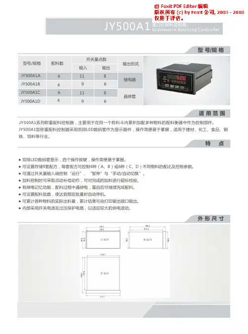
JY500A配料控制器深圳龙芯智业科技有限公司深圳市南山区南山大道1002号深意工业大厦电话:0755-********传真:0755-********电子邮箱:szlongxin@公司网址:V1.0Copyright©2008深圳龙芯智业科技有限公司序言首先感谢您选用深圳市龙芯智业科技有限公司JY500系列配料控制器产品。
深圳市龙芯智业科技有限公司是一家专业从事称重仪表及相关控制系统研发及生产的高新技术企业,所生产的JY500系列称重配料控制仪表性能可与国际领军品牌媲美,并已成功远销印度、巴基斯坦等国外市场。
JY500系列配料控制器、定量包装控制器、皮带秤显示控制器、称重显示仪表等四大系列称重产品广泛应用在工矿企业的配料秤、定量包装秤、电子皮带秤等自动化称重检测产品中。
公司本着“没有最好,只有更好”的设计理念,以精良的设计、周到的售后服务赢得了新老用户的高度认可,致力于为客户提供在建筑、电力、煤炭、冶金、化工、粮食及医药等行业称重控制、配料控制、称重检测及定量包装技术解决方案。
JY500A系列配料控制器是针对混凝土搅拌及沥青混合料设备的配料控制过程而开发生产的一种称重控制仪表,采用世界上最先进的高精度∑-ΔA/D转换芯片和具有高抗干扰性能的单片机为核心,充分考虑到工业现场的复杂性,以精心的软硬件设计,使生产和管理得到有利的保障。
本产品也适用于钢铁、冶金、化工、粮食、饲料等需要配料控制的行业。
JY500A系列配料控制器具有如下功能及特点◆集称重、显示、通讯和配料控制于一体◆内部集成的开关电源,电压在185V~265V内可以正常使用◆具有模拟、数字双重滤波功能◆自动错误诊断,易发现和解决问题◆提供完整的物料配料控制功能◆可实现自动/手动配料◆配料过程可随时暂停,重启后继续配料◆具有自动零位跟踪功能◆可实现上电自动归零◆具有配料启动自动去皮功能◆可控制1~4种不同种类的物料◆所有物料都具有自动快配料、慢配料控制,并具有点动补偿功能◆可随意修改配方◆配料批数随意设置,定量生产更为方便Copyright©2008深圳龙芯智业科技有限公司1◆具有自动物料消耗累计◆具有自动冲力延时功能◆具有手动/自动设定提前量修正功能◆具有密码权限设置功能,方便管理◆可设置置零范围、去皮范围、过载范围及允差范围、滤波强度◆日期、时间显示及设定功能在使用JY500A系列配料控制器之前,请认真阅读本说明书,以确保正确使用并充分发挥其优越性能,并使本设备达到更佳的使用效果。
第一部分操作快速入门一、准备将三相四线电源线,各电机电源线,电磁阀控制线,传感器信号线,遥控手柄或上、下限位控制线(有些配料机不需上、下限位控制,则无此接线)接入端子排的相应位置。
控制柜及仪表必须可靠接地,以防止雷击和保护设备及人身安全。
二、上电控制器接入电源之前,请检查使用的电压范围,一定注意是否在交流 187V ~242V 之间,频率为50Hz±2%范围内。
如您使用的电源不能满足这一要求,需加交流稳压电源。
操作空气开关手柄,给控制系统通电,并使系统预热30分钟。
(通电后严禁秤体进行电气焊等造成仪表及传感器易损坏的操作)三、校称设备第一次使用或长时间使用后称量不准确时,需进行校称操作,正常情况下无需校称。
PLY 配料控制器只有处于“停止”状态(运行状态指示灯灭)时,才能进行校称操作。
校称前首先清空称量斗,为确保校称值的精确性,用户必须在控制器通电半小时后,再进行校称操作。
校称前,称体应稳定(无摆动)、平衡,并保证所使用的传感器受力一致。
否则应先进行称体调整。
校称时按键顺序及显示内容如下。
按键及操作按校称键按键和键修改显示按确认键显示说明闪烁显示校称操作需输入校称密码,闪烁位是当前修改位。
闪烁显示1234为有效校称密码,键为数字增加键,键为数字移位键显示密码输入正确,控制器转入“ 校零点”按确认键闪烁显示* * * *校零点完毕,控制器转入“校满度”,**** 为上次校称时,控制器接受的砝码值。
( *为任意数)在称量斗中放上标准砝码(假如为 2000 千克 )按键和闪烁显示2000 为称量斗中放键入的砝码重量修改显示按确认键显示校准完毕,控制器显示称量斗中砝码重量卸下砝码显示称量斗中没有砝码* *四、控制器配方(定值和落差)设定PLY 配料控制器,最多可控制四路上料、两路卸料。
因此,如果实际只用1 至3 路,对不用的路数的定值,必须设定为零。
另外配料控制器只有处于“ 停止”状态(运行状态指示灯灭)才可以进行配方号的选择。
HY-MMC型电动机保护控制器使用说明书北京华园经纬机电技术有限公司重要提示感谢您使用北京华园经纬机电技术有限公司的产品。
为了安全、正确、高效地使用本装置,请您务必注意以下重要提示:1)本说明书仅适用于:HY-MMC-500系列数字电动机保护测控装置V1.07及以上版本的保护程序。
2)请仔细阅读本说明书,并按照说明书的规定设定、测试和操作。
如有随机资料,请以随机资料为准。
3)为防止装置损坏,严禁带电插拔装置各插件、严禁触摸印制电路板上的芯片和器件。
4)请使用合格的测试仪器和设备对装置进行试验和检测。
5)本装置读写保护数据的操作密码是:1000。
6)装置出厂前通道系数已设定好,请勿随意调整。
目录1.产品概述1.1 产品用途-----------------------------------------------------------------------------------------------------1 1.2 主要功能-----------------------------------------------------------------------------------------------------1 1.3 装置主要特点-----------------------------------------------------------------------------------------------3 1.4 技术参数-----------------------------------------------------------------------------------------------------3 1.5 使用环境-----------------------------------------------------------------------------------------------------4 1.6 主要功能及数据--------------------------------------------------------------------------------------------5 2.装置结构尺寸和安装方式2.1 主控单元外形尺寸及安装方式--------------------------------------------------------------------------6 2.2 显示单元外形尺寸及安装方式--------------------------------------------------------------------------6 2.3 显示模块-----------------------------------------------------------------------------------------------------7 2.4 主控单元-----------------------------------------------------------------------------------------------------10 3.保护特性及参数整定3.1 描述-----------------------------------------------------------------------------------------------------------13 3.2 速断保护、过流保护--------------------------------------------------------------------------------------13 3.3 启动超时保护-----------------------------------------------------------------------------------------------13 3.4 过负荷保护--------------------------------------------------------------------------------------------------13 3.5 堵转保护-----------------------------------------------------------------------------------------------------13 3.6 缺相保护-----------------------------------------------------------------------------------------------------14 3.7 反时限过流保护--------------------------------------------------------------------------------------------14 3.8 电流不平衡保护--------------------------------------------------------------------------------------------15 3.9 过热保护----------------------------------------------------------------------------------------------------15 3.10 低压保护---------------------------------------------------------------------------------------------------17 3.11 接地保护---------------------------------------------------------------------------------------------------17 3.12 过压保护---------------------------------------------------------------------------------------------------17 3.13 欠载保护---------------------------------------------------------------------------------------------------17 3.14 失压重启动------------------------------------------------------------------------------------------------18 3.15 PT断线监视-----------------------------------------------------------------------------------------------18 3.16 CT断线功能-----------------------------------------------------------------------------------------------18 3.17波特率---------------------------------------------------------------------------------------------18 3.18模拟量输出---------------------------------------------------------------------------------------------------18 附录 1 定值整定表-----------------------------------------------------------------------------------------------------19附录 2 配置清单--------------------------------------------------------------------------------------------------------21附录3 典型控制模式直接启动单向模式及接线----------------------------------------------------------------------------23 直接启动双向可逆模式及接线----------------------------------------------------------------------24 星三角启动双继电器模式及接线-------------------------------------------------------------------25 电阻降压启动模式及接线----------------------------------------------------------------------------26 自耦变压器启动双继电器模式及接线-------------------------------------------------------------27附录 4 用户操作界面--------------------------------------------------------------------------------------------28附录 5 HY-MMC-500开孔尺寸图---------------------------------------------------------------------------29 附录 6 通讯规约---------------------------------------------------------------------------------------301 .产品概述1.1产品用途HY-MMC-500系列数字电动机保护控制装置(以下简称控制装置)是针对交流50Hz 、额定工作电压不超过660V 的低压电动机设计的集保护、测量、控制和通讯为一体的低压电动机综合保护装置。
sanvo hy-500 功率放大器说明书1、1简介SANVO HY-500功率放大器是应急广播系统配套产品,它是在《GB16806-2006消防联动控制系统》国家标准指导下设计并生产的产品,完全满足GB16806-2006国家标准。
HY2733D广播功率放大器(以下简称设备)是消防应急广播系统的配套产品之一。
它与相应的广播音源设备(CD播放盘、MP3播放盘)、广播区域控制盘和广播终端设备(音箱)配合,实现现场的消防应急广播。
1、2结构形式本设备采用标准上架结构形式:高:88、1mm(2U标准)宽:482、6mm厚:305mm1、3工作环境温度:0℃~+40℃湿度:≤95%1、4设备供电本设备工作电源为交流220V,主电备电均采用交流220V供电,主备电自动切换,主电优先。
2、电路说明本设备由电源、音频前置放大,音频推动电路,功率放大,电平显示,主备电切换等电路组成。
2、1音频前置放大:完成对音频输入信号的预放大。
2、2音频推动电路:完成对音频的再放大,用于推动功率放大电路。
2、3功率放大:完成对音频信号的末级放大。
2、4主备电切换电路:本机主备电均采用交流220V,主备电源自动切换,当主用和备用电源同时接入时,主电优先供电。
2、5电平显示电路:指示音频输出信号幅度,动态显示。
3、主要技术指标3、1输入特性3、1、1输入阻抗:600Ω。
3、1、2输入电平:775mV。
3、2输出特性3、2、1定压输出:120V3、2、2频率特性:80Hz~8KHz(90V~145V)3、2、3谐波失真:≤5%3、2、4噪声电平:<37mV3、3指示灯说明3、3、1前面板示意图3、3、2指示灯说明①、工作指示灯:绿灯亮表示本机工作正常。
②、故障指示灯:故障指示灯视故障状态而不同。
故障灯常亮:表示本机工作异常或音频输出线处于短路,本机已经处于保护状态。
如果音频输出线短路故障排除,需将电源关闭,然后再重新启动电源,才能解除指示灯常亮状态。
柴油机调速控制器SHY-500使⽤⼿册警告!安装胜业智能化控制器,所有的电⽓安装和维护⼯作都必须由专业的电⽓⼯程师进⾏。
警告!控制器是不可以在现场维修的机器,不要试图修理损坏的单元,请与供应商或者⽣产⼚家联系。
警告!不要试图进⾏本⼿册中没有涉及的任何测量,器件的更换或其他维修⼯作,否则将可能导致保修失败,危及正常运⾏,延长设备停机时间和增加费⽤等后果。
为确保您的⼈⾝、设备以及财产的安全,在使⽤之前,请您务必阅读本⼿册,并在以后的搬运、安装、运⾏、调试与检修过程中遵照执⾏。
⽬录⼀.概述 (4)⼆.性能和特点 (4)三.产品技术指标及规格 (5)四.操作说明 (6)1.⼀体化操作界⾯ (6)2.按键名称及功能描述 (6)3.⾃动开机/停机操作 (7)4.⼿动开机/停机操作 (8)五.保护功能及报警信息 (8)1.预报警信息[不停机] (8)2.报警信息[停机] (10)六.控制器背⾯板及端⼦说明 (11)七.系统参数设置及功能说明 (12)1.参数设置内容及描述(表1) (12)2.开关量输出端⼝内容 (表2) (16)3.开关量输⼊端⼝内容 (表3) (17)4.系统附件(⽤户⾃备或定货时另购)(表4) (17)⼋.参数设置及显⽰ (18)九.试运⾏ (22)⼗.典型应⽤ (23)⼗⼀.安装指南 (26)⼗⼆.出⼚默认值 (28)⼗三.故障排除 (29)⼀.概述SHY系列柴油机调速智能控制器采⽤⾼性能的微处理技术,结合⾼可靠性的设计,具有很⾼的可靠性及稳定性,实现了多种参数的精密测量、报警保护值设定等功能;适⽤于发动机/发电机组⾃动化控制系统,可实现机组的⼿动、⾃动开机/停机,数据测量、⾃动调速和报警保护等控制功能。
SHY系列柴油机调速智能控制器采⽤192X64屏幕液晶(LCD)显⽰,所有参数可从控制器前⾯板设定。
其结构美观紧凑、接线简单,运⾏可靠,⼴泛应⽤于各类型⽔泵机组、发电机组⾃动化控制系统。
设备型号+名称HY-500多功能弧焊机操作规程规格及关键技术参数输入电源: AC3×380V/50HZ额定输入功率KVA:24额定输入电流: 39A额定输出电流: 500A额定输出电压: 40V电流调节范围: 30~500A额定负载持续率: 60%劳动防护要求穿戴焊工手套、焊工服、耳塞、口罩。
操作步骤重点操作内容重要风险提示风险消减和预控措施一、日常检查1、焊机电源线、引出线及接线点是否良好,2、保证绞门关闭、侧面面板置于本位。
/ /二、作业前检查检查保护性接地线PE是否可靠接地/ / 检查焊接现场周围是否有易燃易爆物品检查周围空气中的灰尘、酸、腐蚀性气体或物质是否超过正常含量检查焊接电源的倾斜度是否超过15度检查焊机面板参数显示是否正常检查焊接线缆、机壳有无破损三、作业前准备穿戴好焊工面罩、口罩、耳塞、焊工手套等劳保装备/ /四、操作流程打开焊机电源开关,风机转动,焊机开始工作1、漏电、触电2、焊接飞溅及弧光会造成人体伤害1、按要求进行作业前各项检查2、穿戴齐全劳保着装。
被弧光灼伤后,用冷毛巾和冰块冷敷。
使用牛奶清洗,严重情况下就医。
根据需要通过功能选择开关选择合适的焊接方法:①纤维素功能适用于E6010等纤维素焊条下的下向焊工艺,具有起弧、推力调节,如果接上YH-120管道送丝机,可用送丝机电位器调节电流;②氩弧功能使用于简易氩弧焊工艺;③低氢功能适用于碱性、酸性焊条的普通手工焊工艺具有起弧、推力调节,同时如果接上YH-120管道送丝机,可用送丝机电位器调节电流;④药芯功能与YH-120管道送丝机配用适用于1.6-2.0mm的药芯焊丝的自保护焊工艺,电压从15V—50V连续可调,且送丝机带数显表,可显示预设与实际的电流,电压。
(3) 焊接系统的连接:按照说明书要求准确连接焊接系统;(4) 打开空气开关保护罩,将空气开关置于闭合状态,然后盖上空气开关的保护罩。
焊接:焊接前先检查电路是否连接正确、可靠、电网电压是否符合要求:(1)打开焊机面板上的电源开关,给焊机通电,此时风机转动,电源的指示灯亮;①如果选择低氢和纤维素档,电流表显示预设电流,电压表显示空载电压(65-80v);②如果选择氩弧焊档,电流表显示预设电流,电压显示000;③如果选择药芯焊档,电流表显示000,电压表显示预设电压。
CREATE 纯水机控制器说明书河北科瑞达仪器科技有限公司一、仪器主要特点1.本仪表为反渗透控制器和在线电导/电阻率仪表的组合式控制仪表。
可完成RO系统的运行检测、状态控制和水质电导/电阻率的在线监控(将PLC控制器和电阻/电导率仪合二为一)。
2.绿色背景光、大屏幕(像素为240*128)可监控显示3路电导/电阻(入水TDS、RO产水TDS、高纯水出水)。
3.多级菜单式操作,动画式工作模式。
4.四位密码保护,可以输入或修改用户需要的多组参数,可满足自动运行的各项要求,功能丰富,操作简便。
(出厂默认用户设置密码0000,可任意修改。
用户万能密码0521。
工厂参数设置密码8951,可设置各电极的零点和满度)。
5.完善的消毒程序,在加入消毒剂后,自动完成消毒所有步骤!图-1 自来水进水结构流程二、技术指标主要技术指标:1.电源电压:DC(直流)24V(设计外壳时需加一个电源开关)2.功耗:≤7.2W3.湿度:≤85%RH4.环境条件:1)温度:0~60℃;5.准确度:1.5级6.输出接点负载能力:5A/250V AC 3A/24V DC7.采集结果更新速率:≤1秒/次8.电导池工作压力:0~0.5Mpa9.自动温度补偿:1~49℃10.界面方式:LCD屏英文/图标显示、触摸按键11. 量程:一路电阻0—18.2M Ω(配0.05CM -1电极);两路TDS 0—100PPM 和0—1000PPM12. 按键超时返回。
正常运行中在非主界面下,2分钟内没有‘按键’被触发,系统将自动返回主界面。
三、控制流程简介1. 开机上电显示:‘HITECH ’(如图1) ,显示时间为5秒阀(为TDS1进水水质检测作准备)。
图1 图22. 检测无水开关,判断供水状况。
无水则报警(如图2)。
3. 检测TDS1进水电导,是否超标。
超标则显示当前的值,(如图3)并报警。
待正常后继续或用户按下‘确认’ 键忽略。
图3 图44. 开机清洗,屏幕显示清洗时动画画面(如图4),时间约20秒。