滤油器支架的复合模设计
- 格式:doc
- 大小:1.23 MB
- 文档页数:54


(数控模具设计)模具五金空气滤清器壳正反拉伸复合模设计摘要随着中国工业不断地发展,模具行业也显得越来越重要。
本论文便是设计加工空气滤清器壳的模具。
首先对加工零件进行了加工工艺和结构工艺的分析。
通过计算毛坯尺寸和拉深系数提出了四种方案,最后确定采用落料、正反拉深复合模。
对模具的排样做出了合理的布置,使材料利用率达到较高的水平。
计算了冲压过程中所需要的各种冲压工艺力,包括落料力、卸料力、压边力、拉深力、顶料力等,并对压力机进行了合理的吨位初选。
复合模在结构上采用了正装的形式,计算出了落料、正拉深和反拉深工作部分的尺寸。
对模具的闭合高度进行了合理的确定,还设计出模具的主要零件落料凹模、凸凹模、反拉深凸模、反拉深凹模、凹模固定板等。
列出了模具所需零件的详细清单,并给出了合理的装配图。
由于拉深的深度较大,对压力机的电机也进行了功率校核并提出了润滑的附加工序,能使拉深顺利完成。
最后对模具的一个主要零件导套进行了简单的加工工艺路线的制定。
本设计对于采用单动压力机进行正反拉深具有一定的参考作用。
关键词毕业论文;模具设计;复合模;正反拉深ABSTRACTDevelops unceasingly along with the Chinese industry, the mold profession also appears more and more importantly. The present paper then is designs the processing air filter shell the mold. First has carried on the processing craft and the structure craft analysis to the processing components. Proposed through the computation semifinished materials size and the d r a w i ng coefficient four kind of plans,finally determined uses falls the m a t e r ial,the pro and con drawing superposable die.Has made the reasonable arrangement to the mold platoon type, enables the material use factor to achieve the high level. Has calculated each ramming craft strength which in the ramming process needs, including falls nearby the material strength, the ex-denning strength, the pressure the strength, thedrawing strength, the top material strength and so on, and has carried on the reasonable tonnage primary election to the press. The superposable die has used the true thing form in the structure, calculated fell the material, the drawing and the counter- drawing effective range size. Closed has carried on the reasonable determination highly to the mold, but also designs the mold the major parts to fall the material concave mold, the convex-concave mold, the counter- drawing raised mold, the counter- drawing concave mold, the concave mold dead plate and so on. Listed the mold to need the components the detailed detailed list, and has produced the reasonable assembly drawing. Because the drawing depth is big, also carried on the powerto the press electrical machinery to examine and to propose the lubrication attachment working procedure, could cause the drawing smoothly to complete. Finally led the wrap to mold major parts to carry on the simple processing craft route formulation. This design regarding uses the single acting press to carry on the pro and con drawing to have the certain reference function.Key words graduation thesis; mold design; superposable die; pro andcon drawing目录1 分析零件的工艺性∙∙∙∙∙∙∙∙∙∙∙∙∙∙∙∙∙∙∙∙∙∙∙∙∙∙∙∙∙∙∙∙∙∙∙∙∙∙∙∙∙∙∙∙∙∙∙∙∙∙∙∙∙∙12 确定工艺方案∙∙∙∙∙∙∙∙∙∙∙∙∙∙∙∙∙∙∙∙∙∙∙∙∙∙∙∙∙∙∙∙∙∙∙∙∙∙∙∙∙∙∙∙∙∙∙∙∙∙∙∙∙∙∙∙∙∙2 2.1 计算毛坯尺寸∙∙∙∙∙∙∙∙∙∙∙∙∙∙∙∙∙∙∙∙∙∙∙∙∙∙∙∙∙∙∙∙∙∙∙∙∙∙∙∙∙∙∙∙∙∙∙∙∙∙∙∙2 2.2 计算拉深次数∙∙∙∙∙∙∙∙∙∙∙∙∙∙∙∙∙∙∙∙∙∙∙∙∙∙∙∙∙∙∙∙∙∙∙∙∙∙∙∙∙∙∙∙∙∙∙∙∙∙∙∙42.2.1 正拉深∙∙∙∙∙∙∙∙∙∙∙∙∙∙∙∙∙∙∙∙∙∙∙∙∙∙∙∙∙∙∙∙∙∙∙∙∙∙∙∙∙∙∙∙∙∙∙∙∙∙∙∙∙42.2.2 反拉深∙∙∙∙∙∙∙∙∙∙∙∙∙∙∙∙∙∙∙∙∙∙∙∙∙∙∙∙∙∙∙∙∙∙∙∙∙∙∙∙∙∙∙∙∙∙∙∙∙∙∙∙∙52.3 确定工艺方案∙∙∙∙∙∙∙∙∙∙∙∙∙∙∙∙∙∙∙∙∙∙∙∙∙∙∙∙∙∙∙∙∙∙∙∙∙∙∙∙∙∙∙∙∙∙∙∙∙∙∙∙53 主要工艺参数的计算∙∙∙∙∙∙∙∙∙∙∙∙∙∙∙∙∙∙∙∙∙∙∙∙∙∙∙∙∙∙∙∙∙∙∙∙∙∙∙∙∙∙∙∙∙∙∙∙∙∙∙∙6 3.1 确定排样、裁板方案∙∙∙∙∙∙∙∙∙∙∙∙∙∙∙∙∙∙∙∙∙∙∙∙∙∙∙∙∙∙∙∙∙∙∙∙∙∙∙∙∙∙∙∙∙∙6 3.2 确定各中间工序尺寸∙∙∙∙∙∙∙∙∙∙∙∙∙∙∙∙∙∙∙∙∙∙∙∙∙∙∙∙∙∙∙∙∙∙∙∙∙∙∙∙∙∙∙∙∙∙8 3.3 计算工艺力、初选设备∙∙∙∙∙∙∙∙∙∙∙∙∙∙∙∙∙∙∙∙∙∙∙∙∙∙∙∙∙∙∙∙∙∙∙∙∙∙∙∙∙∙∙∙93.3.1 落料、正拉深过程∙∙∙∙∙∙∙∙∙∙∙∙∙∙∙∙∙∙∙∙∙∙∙∙∙∙∙∙∙∙∙∙∙∙∙∙∙∙∙∙∙∙∙9(1) 落料力∙∙∙∙∙∙∙∙∙∙∙∙∙∙∙∙∙∙∙∙∙∙∙∙∙∙∙∙∙∙∙∙∙∙∙∙∙∙∙∙∙∙∙∙∙∙∙∙∙∙∙∙9(2) 卸料力∙∙∙∙∙∙∙∙∙∙∙∙∙∙∙∙∙∙∙∙∙∙∙∙∙∙∙∙∙∙∙∙∙∙∙∙∙∙∙∙∙∙∙∙∙∙∙∙∙∙∙∙9(3) 拉深力∙∙∙∙∙∙∙∙∙∙∙∙∙∙∙∙∙∙∙∙∙∙∙∙∙∙∙∙∙∙∙∙∙∙∙∙∙∙∙∙∙∙∙∙∙∙∙∙∙∙∙10(4) 压边力∙∙∙∙∙∙∙∙∙∙∙∙∙∙∙∙∙∙∙∙∙∙∙∙∙∙∙∙∙∙∙∙∙∙∙∙∙∙∙∙∙∙∙∙∙∙∙∙∙∙∙103.3.2 反拉深过程∙∙∙∙∙∙∙∙∙∙∙∙∙∙∙∙∙∙∙∙∙∙∙∙∙∙∙∙∙∙∙∙∙∙∙∙∙∙∙∙∙∙∙∙∙∙∙∙11(1) 反拉深力∙∙∙∙∙∙∙∙∙∙∙∙∙∙∙∙∙∙∙∙∙∙∙∙∙∙∙∙∙∙∙∙∙∙∙∙∙∙∙∙∙∙∙∙∙∙∙∙∙11(2) 顶料力∙∙∙∙∙∙∙∙∙∙∙∙∙∙∙∙∙∙∙∙∙∙∙∙∙∙∙∙∙∙∙∙∙∙∙∙∙∙∙∙∙∙∙∙∙∙∙∙∙∙∙113.3.3 拉深功的计算∙∙∙∙∙∙∙∙∙∙∙∙∙∙∙∙∙∙∙∙∙∙∙∙∙∙∙∙∙∙∙∙∙∙∙∙∙∙∙∙∙∙∙∙∙∙113.3.4 初选压力机∙∙∙∙∙∙∙∙∙∙∙∙∙∙∙∙∙∙∙∙∙∙∙∙∙∙∙∙∙∙∙∙∙∙∙∙∙∙∙∙∙∙∙∙∙∙∙∙114 模具的结构设计∙∙∙∙∙∙∙∙∙∙∙∙∙∙∙∙∙∙∙∙∙∙∙∙∙∙∙∙∙∙∙∙∙∙∙∙∙∙∙∙∙∙∙∙∙∙∙∙∙∙∙∙∙∙∙13 4.1 模具结构形式的选择∙∙∙∙∙∙∙∙∙∙∙∙∙∙∙∙∙∙∙∙∙∙∙∙∙∙∙∙∙∙∙∙∙∙∙∙∙∙∙∙∙∙∙∙∙13 4.2 模具工作部分尺寸计算∙∙∙∙∙∙∙∙∙∙∙∙∙∙∙∙∙∙∙∙∙∙∙∙∙∙∙∙∙∙∙∙∙∙∙∙∙∙∙∙∙∙∙134.2.1 落料∙∙∙∙∙∙∙∙∙∙∙∙∙∙∙∙∙∙∙∙∙∙∙∙∙∙∙∙∙∙∙∙∙∙∙∙∙∙∙∙∙∙∙∙∙∙∙∙∙∙∙∙∙∙134.2.2 正拉深∙∙∙∙∙∙∙∙∙∙∙∙∙∙∙∙∙∙∙∙∙∙∙∙∙∙∙∙∙∙∙∙∙∙∙∙∙∙∙∙∙∙∙∙∙∙∙∙∙∙∙∙154.2.3 反拉深∙∙∙∙∙∙∙∙∙∙∙∙∙∙∙∙∙∙∙∙∙∙∙∙∙∙∙∙∙∙∙∙∙∙∙∙∙∙∙∙∙∙∙∙∙∙∙∙∙∙∙∙165 选用模架、确定闭合高度∙∙∙∙∙∙∙∙∙∙∙∙∙∙∙∙∙∙∙∙∙∙∙∙∙∙∙∙∙∙∙∙∙∙∙∙∙∙∙∙∙∙∙∙∙∙∙16 5.1 模架的选用∙∙∙∙∙∙∙∙∙∙∙∙∙∙∙∙∙∙∙∙∙∙∙∙∙∙∙∙∙∙∙∙∙∙∙∙∙∙∙∙∙∙∙∙∙∙∙∙∙∙∙∙∙16 5.2 模具的闭合高度∙∙∙∙∙∙∙∙∙∙∙∙∙∙∙∙∙∙∙∙∙∙∙∙∙∙∙∙∙∙∙∙∙∙∙∙∙∙∙∙∙∙∙∙∙∙∙∙∙165.3 压力中心∙∙∙∙∙∙∙∙∙∙∙∙∙∙∙∙∙∙∙∙∙∙∙∙∙∙∙∙∙∙∙∙∙∙∙∙∙∙∙∙∙∙∙∙∙∙∙∙∙∙∙∙∙∙∙176 模具的主要零部件结构设计∙∙∙∙∙∙∙∙∙∙∙∙∙∙∙∙∙∙∙∙∙∙∙∙∙∙∙∙∙∙∙∙∙∙∙∙∙∙∙∙∙∙∙∙∙17 6.1 落料凹模∙∙∙∙∙∙∙∙∙∙∙∙∙∙∙∙∙∙∙∙∙∙∙∙∙∙∙∙∙∙∙∙∙∙∙∙∙∙∙∙∙∙∙∙∙∙∙∙∙∙∙∙∙∙∙17 6.2 凸凹模∙∙∙∙∙∙∙∙∙∙∙∙∙∙∙∙∙∙∙∙∙∙∙∙∙∙∙∙∙∙∙∙∙∙∙∙∙∙∙∙∙∙∙∙∙∙∙∙∙∙∙∙∙∙∙∙∙18 6.3 反拉深凸模∙∙∙∙∙∙∙∙∙∙∙∙∙∙∙∙∙∙∙∙∙∙∙∙∙∙∙∙∙∙∙∙∙∙∙∙∙∙∙∙∙∙∙∙∙∙∙∙∙∙∙∙∙19 6.4 反拉深凹模∙∙∙∙∙∙∙∙∙∙∙∙∙∙∙∙∙∙∙∙∙∙∙∙∙∙∙∙∙∙∙∙∙∙∙∙∙∙∙∙∙∙∙∙∙∙∙∙∙∙∙∙∙20 6.6 上垫板∙∙∙∙∙∙∙∙∙∙∙∙∙∙∙∙∙∙∙∙∙∙∙∙∙∙∙∙∙∙∙∙∙∙∙∙∙∙∙∙∙∙∙∙∙∙∙∙∙∙∙∙∙∙∙∙∙236.7 凹模固定板∙∙∙∙∙∙∙∙∙∙∙∙∙∙∙∙∙∙∙∙∙∙∙∙∙∙∙∙∙∙∙∙∙∙∙∙∙∙∙∙∙∙∙∙∙∙∙∙∙∙∙∙∙247 模具的整体安装∙∙∙∙∙∙∙∙∙∙∙∙∙∙∙∙∙∙∙∙∙∙∙∙∙∙∙∙∙∙∙∙∙∙∙∙∙∙∙∙∙∙∙∙∙∙∙∙∙∙∙∙∙∙∙25 7.1 模具的总装配∙∙∙∙∙∙∙∙∙∙∙∙∙∙∙∙∙∙∙∙∙∙∙∙∙∙∙∙∙∙∙∙∙∙∙∙∙∙∙∙∙∙∙∙∙∙∙∙∙∙∙257.2 模具零件∙∙∙∙∙∙∙∙∙∙∙∙∙∙∙∙∙∙∙∙∙∙∙∙∙∙∙∙∙∙∙∙∙∙∙∙∙∙∙∙∙∙∙∙∙∙∙∙∙∙∙∙∙∙∙268 选定冲压设备∙∙∙∙∙∙∙∙∙∙∙∙∙∙∙∙∙∙∙∙∙∙∙∙∙∙∙∙∙∙∙∙∙∙∙∙∙∙∙∙∙∙∙∙∙∙∙∙∙∙∙∙∙∙∙∙∙278.1 压力机的规格∙∙∙∙∙∙∙∙∙∙∙∙∙∙∙∙∙∙∙∙∙∙∙∙∙∙∙∙∙∙∙∙∙∙∙∙∙∙∙∙∙∙∙∙∙∙∙∙∙∙∙278.2 电动机功率的校核∙∙∙∙∙∙∙∙∙∙∙∙∙∙∙∙∙∙∙∙∙∙∙∙∙∙∙∙∙∙∙∙∙∙∙∙∙∙∙∙∙∙∙∙∙∙∙289 附加工序∙∙∙∙∙∙∙∙∙∙∙∙∙∙∙∙∙∙∙∙∙∙∙∙∙∙∙∙∙∙∙∙∙∙∙∙∙∙∙∙∙∙∙∙∙∙∙∙∙∙∙∙∙∙∙∙∙∙∙∙∙2910 主要零件的加工∙∙∙∙∙∙∙∙∙∙∙∙∙∙∙∙∙∙∙∙∙∙∙∙∙∙∙∙∙∙∙∙∙∙∙∙∙∙∙∙∙∙∙∙∙∙∙∙∙∙∙∙∙∙2911 总结∙∙∙∙∙∙∙∙∙∙∙∙∙∙∙∙∙∙∙∙∙∙∙∙∙∙∙∙∙∙∙∙∙∙∙∙∙∙∙∙∙∙∙∙∙∙∙∙∙∙∙∙∙∙∙∙∙∙∙∙∙∙∙∙32参考文献∙∙∙∙∙∙∙∙∙∙∙∙∙∙∙∙∙∙∙∙∙∙∙∙∙∙∙∙∙∙∙∙∙∙∙∙∙∙∙∙∙∙∙∙∙∙∙∙∙∙∙∙∙∙∙∙∙∙∙∙∙∙∙∙33 致谢∙∙∙∙∙∙∙∙∙∙∙∙∙∙∙∙∙∙∙∙∙∙∙∙∙∙∙∙∙∙∙∙∙∙∙∙∙∙∙∙∙∙∙∙∙∙∙∙∙∙∙∙∙∙∙∙∙∙∙∙∙∙∙∙∙∙34图纸请加 QQ2387670979 或咨询淘宝旺旺 ccc_126全套 CAD1 分析零件的工艺性冲压件工艺性是指冲压零件在冲压加工过程中加工的难易程度。
汽车空气滤清器端盖成型工艺及模具设计摘要冲压成形是一个涉及领域极其广泛的行业,深入到制造业的每个方面,冲压成形加工主要是通过冲压模具来实现。
冲压模具是大批量生产同类产品的工具,是冲压成形的常用工艺装备,也是提高工作效率的有效方法。
汽车空气滤清器端盖结构简单、对称,是典型的冲压件。
在冲压过程中要注意控制冲载程度,加工时,根据零件的结构、形状等一些技术要求,在这里零件材料选用08F钢。
通过确定零件的毛坯尺寸、修边余量,计算得出工作零件在拉深段需要二次拉深,根据对零件进行工艺分析,最终设计了三幅模具:落料冲孔模、二次拉深模、翻内外边模。
落料冲孔模设计的重点在于凸凹模具的设计以及热处理,对零件裁板排样采用单排。
二次拉深模着重于工艺力的计算,根据工艺力大小选择合适的压力机。
翻边模的难点在于确定合理的凸凹模间隙,因为翻边时凸凹模具跟工件有大量的接触。
最终通过CAD制图软件绘制了落料冲孔、拉深、翻边三幅模具装配图。
本文就以汽车空气滤清器端盖的形成介绍了冲压模具设计的全过程。
关键词:端盖模具设计落料冲孔拉深翻边Molding Process and Mold Design of Auto Air Filter CoverAbstract Stamping is a very wide range of industries involved in the field, deep into every aspect of the manufacturing sector, mainly through the punch press stamping dies to achieve. Stamping die is a tool for mass production of similar products, is commonly used stamping process equipment. Because the Auto air filter cover simple structure, symmetry, is a typical stampings. In the stamping process should pay attention to controlling impulse load level, processing, according to the parts of the structure, shape, and some other technical requirements, where the parts and materials used 08F steel. By identifying parts of the rough size, trimming margin, calculated working parts in the drawing sections require secondary deep drawing parts for process analysis based on the final design of the three molds: blanking punching die, the second pull deep mold, turning inside outside mold. Blanking punching mold design focuses punch mold designand heat treatment on the part nesting cutting board with a single row. Quadratic model focuses on the process of drawing force calculation, choose the right size according to the process force presses. Flanging die difficulty lies in determining a reasonable punch and die clearance, as flanging punch and die when a large number of contacts with the workpiece. Ultimately through CAD drawing software to draw a blanking punching, deep drawing, flanging three mold assembly drawing. This paper focuses on the formation of auto air filter cover introduced stamping die design process.Key word:End cover Mold design Blanking punching Deep drawing flanging目录第一章绪论 (11.1 汽车空气滤清器的作用 (11.2 汽车空气滤清器端盖的的特点对工艺设计的影响 (11.3 国内外CAD/CAM软件在冲压模具中的应用 (1第二章汽车空气滤清器端盖成形工艺分析以及工艺方案的确定 (32.1 冲压工艺分析 (32.2 确定冲压工艺方案 (5第三章汽车空气滤清器落料冲孔模具的设计 (63.1滤清器端盖零件的工艺分析及理论计算 (63.2落料冲孔凸凹模的设计 (63.3 冲裁力的计算及压力机的选取 (103.4 落料冲孔模压料、卸料及推件装置的设计 (11 3.5 落料冲孔模具模架的设计 (113.6 汽车空气滤清器落料冲孔模具图 (123.7 凸凹模材料热处理工艺 (13第四章汽车空气滤清器二次拉深模具的设计 (16 4.1 二次拉深力的计算 (164.2 压力中心及压力机的选择 (174.3 二次拉深凸凹模的设计 (184.4 压料板、卸料、导向零件的设计 (214.5 汽车空气滤清器二次拉深模具图 (22第五章汽车空气滤清器翻边模具的设计 (245.1 翻边工艺和翻边力的计算 (245.2 翻边凸凹模的设计 (255.3 翻边模导向零件的设计 (265.4 翻边模具总装图 (27结论 (29致谢............................................ 错误!未定义书签。

滤油器支架模具设计一、引言滤油器是一种常见的汽车零部件,用于过滤发动机内部的润滑油。
滤油器支架是滤油器的重要构成部分,它起到固定滤芯和支撑滤油器的作用。
本文将介绍滤油器支架模具的设计过程,包括设计目标、模具结构、材料选择和制造工艺等内容。
二、设计目标1.提高滤油器支架的强度和耐久性;2.减小滤油器支架的重量;3.提高模具制造过程的效率。
三、模具结构设计滤油器支架模具的设计结构应具备以下特点:1.模具采用分体式结构,便于侧开口和取模操作;2.模具底部设置出料槽,方便滤油器支架脱模过程;3.模具顶部设置进料口和压力板,用于注塑工艺;4.模腔表面采用抛光处理,以提高模具使用寿命;5.模具结构应符合工艺要求和滤油器支架的形状尺寸。
四、材料选择滤油器支架模具的材料应具备以下特点:1.耐磨性:模具需要经受高频次的注塑和脱模操作,因此选择具有良好耐磨性的材料,如优质合金钢;2.导热性:模具需要通过冷却系统来降低温度,因此选择导热性能好的材料,如热处理过的铝合金;3.耐蚀性:模具需要经受注塑材料的腐蚀,因此选择具有良好耐蚀性的材料,如不锈钢。
五、制造工艺滤油器支架模具的制造工艺一般包括以下步骤:1.模具设计:根据滤油器支架的形状和尺寸,进行模具结构设计,确定模腔的尺寸和形状;2.材料选择:根据设计要求,选择合适的模具材料,并进行加工预处理,如淬火、回火等;3.加工制造:利用数控机床进行精密加工,如车削、铣削、磨削等,制造出精度高的模具零部件;4.模具组装:将加工好的零部件进行组装,确保模具结构合理,各部件之间配合良好;5.表面处理:对模具表面进行抛光处理,提高模具的使用寿命和开模效果;6.调试和测试:对制造好的模具进行调试和测试,检查模具的使用性能和开模效果;7.最终产出:通过合格的模具,进行滤油器支架的注塑生产。
六、模具维护与保养为了延长滤油器支架模具的使用寿命和保持模具的正常工作状态,需要进行定期维护和保养:1.定期清洁模具表面和模腔,避免杂质和残留物的积累;2.检查模具结构和零部件的紧固情况,如有松动及时处理;3.注重模具冷却系统的维护,确保冷却效果良好;4.定期进行模具的润滑和防锈处理;5.对模具进行加工磨损和损坏的修复和更换。
毕业设计题目轻型越野车空气滤清器固定架的冲压工艺与模具设计学院机械工程学院专业机械工程及自动化班级机升1001学生学号指导教师二〇一二年五月二十四日摘要冲压成形是一个涉及领域极其广泛的行业,深入到制造业的每个方面,冲压成形加工主要是通过冲压模具来实现。
冲压模具是大批量生产同类产品的工具,是冲压成形的常用工艺装备。
本设计首先根据空气滤清器固定架冲压件的结构特点、生产批量、加工精度进行冲压工艺性分析,确定冲压工艺方案。
空气滤清器固定架成型工序包括两个大的部分:一部分是板材的冲孔落料,另一部分为材料的弯曲工艺。
因此,由冲压工艺性分析所确定的冲压工艺方案是设计四套模具,分别是冲孔、落料复合模、中间弯曲单工序模、外角弯曲单工序模,外角弯曲单工序模。
然后对这四套冲压模具进行工艺计算并设计每套模具所用的零部件:凸模、凹模、凹模固定板、卸料板、弯曲模等。
按照冲压模具的设计的步骤,对各套冲压模具选用合适的导柱、导套、模柄及模架等标准件。
最终完成空气滤清器固定架冲压件的模具设计。
关键词:冲压工艺;复合模;弯曲模;空气滤清器固定架ABSTRACTThe stamping is a very wide range of the areas of industry, into all aspects of manufacturing, stamping forming processing to achieve through the stamping die. The stamping dies are the tools of mass production of similar products is the main process of stamping equipment.The design is first based on the structural characteristics of the air filter holder stampings, production volume, processing precision stamping process analysis to determine the program of stamping process. The air filter holder molding processes, including punching, blanking, bending, stamping process determined by the stamping process analysis program is to design three sets of mold, namely, punching, blanking, bending single-process mode, punching down composite material, bending mode, punching and blanking, bending the middle, both ends of the curved composite mode. And then punching, blanking, bending single-process mode, punching and blanking, bending composite mold, punching and blanking the middle bend, both ends of the curved composite mode, three sets of stamping die process calculation and design of each mold parts: punch, die, punch fixed plate and the fixed plate of the die, stripper plate, bending modulus and so on. In accordance with the steps of stamping die design different sets of stamping dies, the appropriate choice of guide posts, guide sleeve, die handle and mold standard parts. The final completion of the air filter holder of stamping mold design.Key words:Stamping process;Punching blanking the composite modulus;Bending mode目录摘要 (I)ABSTRACT (II)目录 (III)1 前言 (1)2 冲压件的工艺方案的制定 (2)2.1冲压件的工艺性分析 (2)2.1.1冲压件的工艺性 (3)2.1.2冲压件的精度和粗糙度 (4)2.1.3冲压件毛坯尺寸的计算 (4)2.2冲压件工艺方案的分析与制定 (5)2.2.1零件冲压工艺性分析 (5)2.2.2冲压工艺方案的制定 (6)3 冲孔、落料复合模的设计 (8)3.1模具总体结构方案 (8)3.1.1模具结构 (8)3.1.2操作与定位方式 (8)3.1.3卸料方式 (8)3.1.4模架类型的选择 (8)3.2冲压件冲压力的计算 (8)3.3 冲压设备的选择 (10)3.3.1 模具压力中心的确定 (10)3.3.2 凸、凹模间隙值的确定 (10)3.3.3 凸、凹模刃口尺寸的确定 (11)3.4 冲孔、落料复合模主要零部件的结构设计 (14)3.4.1 落料凹模 (14)3.4.2 冲孔凸模 (15)3.4.3 冲孔凹模的设计 (16)3.4.4 凸凹模 (16)3.4.5 螺钉与圆柱销的设计与选用 (17)3.4.6 卸料板 (17)3.4.7 挡料装置 (18)3.4.8 模座 (18)3.4.9 模柄 (18)3.4.10 推杆 (18)3.4.11 导柱、导套 (19)3.4.12 冲模闭合高度的确定 (19)3.5冲孔落料复合模装配图 (19)4 弯曲模的设计 (20)4.1 模具总体结构方案 (21)4.1.1卸料方式 (21)4.1.2模架类型的选择 (21)4.2冲压件弯曲工艺的计算 (21)4.2.1弯曲件展开尺寸的计算 (21)4.2.2弯曲力的计算 (23)4.2.3顶件力和压料力的计算 (24)4.3冲压件弯曲设备的选择 (24)4.4弯曲模模具设计 (25)4.4.1凸模与凹模的圆角半径 (25)4.4.2凹模深度 (26)4.4.3弯曲模凸模和凹模的间隙尺寸 (26)4.4.4模具工作零件结构的确定 (27)4.5弯曲模模架及零件设计 (28)4.5.1后侧导柱模架的选用 (28)4.5.2定位板 (28)4.5.3模柄 (28)4.5.4螺栓 (28)4.5.5上模座 (28)4.5.6下模座 (28)4.6弯曲模装配图及工作图 (28)5 结论 (31)参考文献 (32)致谢 (33)1 前言现阶段我国的冲压模具不论质量、技术和能力,还是在数量上已经有了长足的进步但与世界先进水平和发达国家相比,差距仍然非常很大,一些大型、精度、复杂、长寿命的高档模具都需要每年大量进口,特别是轿车的覆盖件模具,目前仍主要依靠进口。
轿车滤清器端盖冷冲压工艺及多工序复合模设计摘要如今在工艺生产时到处可以看见冷冲压技术的应用,越来越多的零部件加工也离不开冷冲压工艺。
但是相比国外成熟的冲压技术,我国的冲压加工技术水平还有不小的差距。
本次毕业设计是关于轿车滤清器端盖的冷冲压工艺及复合模具设计。
轿车滤清器端盖由于它本身结构简单、两边对称在这里零件材料选用Q235钢。
通过确定零件的毛坯尺寸、修边余量,因为这几方面对在设计冲压工艺时带来了很多的阻碍。
本次课题针对轿车滤清器进行冲压工艺的设计以及凸模,凹模,卸料环,压边圈等模具的设计,并且对模具工作的部分及尺寸进行了设计。
并且通过CAD 软件对模具进行二维以及三维图形的绘制。
对今后轿车滤清器端盖的设计成型以及批量的生产意义重大。
关键词:端盖,模具设计,冲压工艺,复合模,拉深Cooling stamping process and multi-composite die design for carfilter end coverNowadays, the application of cold stamping technology can be seen everywhere in the process production. More and more parts processing can not be separated from cold stamping technology. However, compared with the mature stamping technology abroad, there is still a large gap in the level of stamping technology in China.Car filter end cover structure is simple, symmetrical, is a typical stamping parts. During the stamping process, attention must be paid to controlling the degree of impact. When processing, according to some technical requirements such as the structure and shape of the parts, the Q235 steel is selected for the parts. By determining the blank size and trim margin of the parts, these aspects have brought alot of obstacles to the design of the stamping process. In this paper, the design of the stamping process for car filter and the design of mold such as convex die, concave die, unloading ring, pressing edge ring, and the working part and size of the die are designed. And through CAD software to the mold two and three dimensional graphics drawing. It is of great significance for the design and production of car filters in the future.Key words: end cover, die design, stamping process, composite die, drawing depth1 绪论1.1课题研究背景及目的轿车滤清器是内燃机的重要组成,其性能对内燃机的寿命和安全有重要影响。
XXXX大学毕业设计说明书学生姓名:学号:学院:专业:题目:滤油器支架的复合模具设计指导教师:职称:职称:20**年12月5日摘要本说明书主要是阐述了有关滤油器支架模具设计的基本过程和其主要计算。
全文共由四章组成,他们的内容如下所述。
第一章是设计滤油器支架模具的工艺方案的确定,主要根据所给制件特点加以分析,设计出合理的模具,这里共设计出三套模具。
第二章是落料拉深复合模的设计,其中包括一些典型结构的选择和一些非标准零件的设计。
第三章是冲孔切边复合模的设计,包括各种模具零件的选择和一些零件尺寸的计算。
第四章是弯曲翻边复合模的设计,此章除了沿用了相关类似模具结构外,还进行了简单的计算和零件设计。
鉴于本人的水平所限,在设计中肯定有不足之处存在,也可能有错误出现,恳请评阅老师和各位读者包涵并且批评指正。
关键词:模具复合模零件AbstractThis paper is main elaborates the basic mould design course of the sieveoil implement’s bracket,and expounds the main calculation course for it.There are four parts in this paper, their content as follow.The first chapter is settling the project of the mould design’s craft tothe sieve oil implement’s bracket. It main contains the analysis of the sieveoil implement’s bracket’s characteristics. Make sure design three suitablemoulds. The second chapter is the design of the blanking and drawing compounddies. It contains the choosing of the typical framework of the dies. The designof some accessory. The third chapter is the design of the piercing and trimmingcompound dies. It contains the choosing the caculation of accessory. The forthchapter is the design of bending and flanging compound dies. In addition tousing the similar framework of the dies, it contains some calculation anddesign of accessory.In view of my limited knowledge,I could have made some mistakes in thispaper, I wish my teacher and the readers could help me correct it, thanks! Keywords: mould compound dies accessory目录摘要 (2)Abstract (3)第一章工艺方案的确定 (5)一制件工艺分析 (5)二.模具结构确定 (7)第二章落料拉深复合模的设计 (8)一落料部分 (8)二拉深部分 (10)三模具压力中心的确定 (11)四压力机的选择 (11)五标准零件的选择和非标准零件的设计 (12)第三章冲孔修边复合模的设计 (20)一冲孔部分 (20)二修边部分 (21)三冲裁力计算和压力机的选择 (22)四标准零件的选择和非标准零件的设计 (23)第四章弯曲翻边复合模 (31)一弯曲部分 (31)二翻边部分 (33)三压力中心的确定和压力机的选择 (34)四标准零件的选择和非标准零件的设计 (34)毕业设计总结 (40)参考文献 (41)第一章工艺方案的确定一制件工艺分析滤油器支架结构较为简单、材料为08Al,厚度为1mm。
成型工艺包括落料拉深、冲孔修边、弯曲翻边三部分。
制件上的拉深为浅拉深(最大处也只有 4.4mm)可一次拉深成型,同时制件结构对称,经计算满足冲压工艺要求。
制件在进行冲孔、落料、修边时需要有必要的计算,之后才能确定凸凹模尺寸,这是设计时所必须的,这里体现了最原始的数据资料。
在设计弯曲翻边部分时,要考虑到制件的弯曲回弹现象。
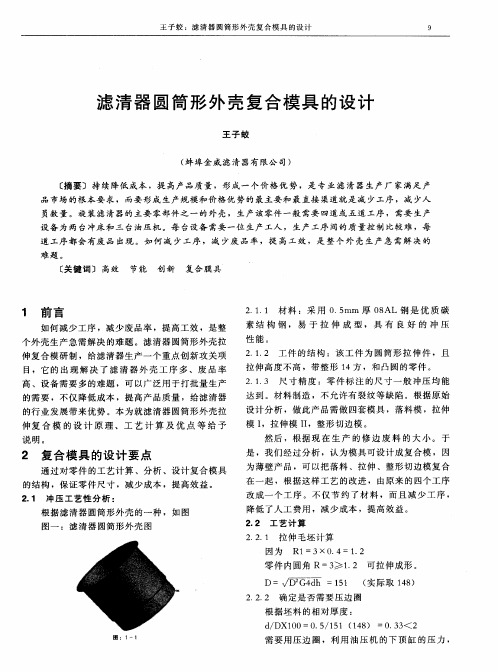
1.毛坯尺寸的确定本人设计的是滤油器支架的模具,设计所依据的是制件图所给数据,具体情况见下图所示图1-1根据《板金冲压工艺手册》P463,对于任何形状旋转体拉深件,其毛坯半径可用下式求得R=1.414∑∑±xl(公式1-1)(rh+)式中l——横的、竖的与斜的直线长度和弧线长度;x ——直线重心和弧线弧心到旋转轴的垂直距离;r ——圆弧半径;h ——圆弧在对称轴上的投影长度。
式中rh 是圆弧的更正值。
对突出弧(弧心在线内)前用正号;对凹弧(弧心在线外)前面用负号。
当所有圆弧都是四分之一圆时,r h =,上式变为 R=1.414∑∑±+)(2r xl (公式1-2)图1-2根据公式1和图2可以计算出毛坯的具体尺寸。
因为是旋转体计算出一半即可。
计算过程如下 R=1.414∑∑±+)(rh xl=1.414)64.025.0(2865.045.2945.2836.6825.1265.25885.205.67-+⨯+⨯+⨯+⨯ =52.91mm因此整个毛坯的尺寸为: D=105.82mm2. 工序的组合和方案的确定通过对制件图的观察,本制件要依次经过落料、拉深、冲孔、修边、弯曲和翻边几道工序,第一道工序是落料和拉深,第二道工序是冲孔和修边,第三道工序是弯曲和翻边。
这样就需要设计出三套模具与之相对应。
由于本制件的生产无其他更符合工艺性和经济性的方案可选择,可以确定本件的生产由如下三套模具完成:第一套模具为落料拉深复合模,完成制件形状的初步确定。
第二套模具为冲孔修边复合模,完成冲孔和修边。
第三套模具为弯曲翻边复合模,完成制件最终形状的确定。
二.模具结构确定要正确选用模具的结构形式,必须根据制件的形状,尺寸,精度要求,材料性能,生产批量,冲压设备,模具加工条件等多方面的因素进行考虑。
在满足冲压件质量要求的前提下,最大限度的降低冲压件的生产成本。
确定模具的结构形式,必须解决好以下的问题。
1.模具类型的确定是简单模复合模,还是级进模。
2.操作方式的确定手工操作自动化操作半自动化操作。
3.进出料方式的确定根据原材料的形式,确定进了方法、取出和整理零件的方法、原材料的定位方法。
4、压料和卸料方式的确定压料或不压料弹性或刚性卸料等。
5、模具精度的确定根据冲压件的精度确定合理的模具加工精度,选择合理的导向方式和固定方式。
基于上述问题,又因为制件为大批量生产并且采用08Al作为制件材料,以及精度等要求的限制,对于冲裁模具,在这里采用复合模结构,其中的一些结构是非常典型的,在我所参阅的书籍中也是很常见的。
制件采用刚性推件装置推出,卸料板采用弹性橡胶卸料板,模架采用对角导柱模架。
对弯曲模具来说,因制件只是简单的弯曲,所以这里可以采用一次弯曲的方法,并且能满足其弯曲要求。
对于拉深模具,因为只是简单的浅拉深,所以能够一次拉深成型。
其结构沿用上述典型结构。
第二章 落料拉深复合模的设计一 落料部分1.冲裁力计算计算冲裁力的目的是合理选择压力机和设计模具,压力机的吨位必须大于所计算的冲裁力,以适应冲裁的要求。
冲裁力的大小主要与材料力学性能、厚度和冲裁件的轮廓长度有关。
用平刃口模具冲裁时,冲裁里F 可按下式计算τKLt F = (公式2-1)式中 L-----冲裁件周边长度(mm )t-----材料厚度(mm )K----系数,平刃口一般取1.3τ----材料抗剪强度(MP )由于要为拉深工序留有修边余量,所以这里取毛坯直径为D=110mm ,此制件为08Al ,根据《冲压工艺与模具设计简明手册》P52表2-2得此钢抗剪强度为Pa 7105.3⨯=τ材料厚度为1毫米周边长度L=345.4 mm所以F=158504N同时,还存在卸料力和推件力,要准确计算这些力是很困难的,实际生产中常用下列经验公式来计算F K F F K F Y Y X X == (公式2-2) 式中,F 为冲裁力Y X K K 为卸料力,推料力系数。
见《冲压工艺与模具设计》P52表2-2得Y XK K 取0.035和0.05即 N F X 64.5547158504035.0=⨯=N F Y 2.792515850405.0=⨯=所以总的冲裁力为KN N F F F F Y X Z 17184.170976==++=2.凸凹模尺寸计算本设计采用凸模与凹模配合加工。
对于冲裁形状复杂或薄板制件的模具,其凸、凹模往往采用复合加工的方法。
此方法是先加工好凸模或凹模为基准,然后根据此基准配置凹模或凸模,使他们保持一定的间隙。
因此,只需在基准件上标注尺寸和公差,另一件只标注尺寸并注明“XX 尺寸按凸模或凹模配置,保证双面间隙”。
这样,可放大基准件的制造公差。
其公差不再受凸、凹模间隙的影响,制造容易,并容易保证凸、凹模的间隙。
由于复杂形状工件各部分尺寸性质不同,凸模和凹模磨损后,尺寸变化的趋势不同,所以基准件的刃口尺寸计算方法也不同。
落料:应以凹模为基准,然后配置凸模。
凹模磨损后,尺寸变大的尺寸类:先把工件图尺寸化为0∆-A ,再按落料公式进行计算d x A A d δ+∆-=0)( (公式2-3)尺寸变小类,先把工件尺寸化为∆+0B ,然后按公式计算)(d x B B d δ-∆+= (公式2-4)凹模磨损后尺寸不变类尺寸,按下述三种情况进行计算制件尺寸为∆+0C 时 2)5.0(d d C C δ±∆+= 制件尺寸为0∆-C 时 2)5.0(d d c C δ±∆-= (公式2-5)制件尺寸为'∆±C 时 2d d C C δ±=根据〈〈冲压工艺学〉〉P18可知基本尺寸80≥—120mm 时,凹模 Δ=0.035mm ,x=0.5,所以由公式2-3 凹模 00875.00)035.05.0110(+⨯-=A 00875.009825.109+=凸模刃口尺寸按上述凹模的相应部分尺寸配制,保证双面间隙值在0.070-0.090mm 之间(《冲压工艺学P14)二 拉深部分1.零件毛坯尺寸的确定毛坯尺寸在上章中已确定2.拉深系数的确定87.08.105/92/===D d m3.凸凹工作部分尺寸的确定(1)凸凹模圆角半径r d凸凹模圆角半径r d 按制件圆角半径尺寸计算(2)凸凹模间隙c决定凸凹模间隙时,不仅要考虑材质和板厚,还要考虑工件的尺寸精度和表面质量要求。