Arduino基础入门套件教程
- 格式:pdf
- 大小:17.41 MB
- 文档页数:72
林锋教你一步一步玩机器人(arduino)系列------制作篇 (入门组件上)----- 张林锋/文2012-5-28目录1 前言 (3)2. 准备工作 (3)2.1 元器件准备工作 (3)2.2 实验板子准备 (4)3 LED 实验 (5)4 蜂鸣器实验 (7)5.按键实验 (9)6 8*8点阵实验 (11)7 串口实验 (12)8 模拟量输入(电压输入) (16)9 直流电机控制(L298N驱动模块) (18)10 PMW 脉冲宽度调试 (21)11 控制舵机 (22)12 超声波模块 (23)13 巡线防跌模块 (26)14 红外遥控 (27)说明写这系列文章主要目的是和读者一同分享下自己的学习过程,也希望能给读者带来一些帮助,文章部分内容剪裁网络文章,部分自己撰写。
文章内容用于爱好者之间学习,不得用于商业目的。
当然笔者才疏学浅,所书内容难免有缺点和漏洞,还请读者多多海涵,希望能和广大电子爱好者交流心得。
本人QQ:65198204邮箱:65198024@博客:/u/27758246901 前言在淘宝买的Arduino 主板套件终于在26号到了,物流也太慢了,发了4天才到。
套件包含:4轮小车,Arduino MEGA 2560 主板,配套的MEGA Sensor Shield V2.0扩展板,超声波模块,红外遥控模块,寻线防跌模块,舵机。
套件是在27°寒语电子工作室(/)买的,也就是科易互动科技的子站(/)。
备注一下:套件性价比很高,也有配套的相关资料,不过个人觉得配套资料写的不够详细和全面,对于新手制作会带来很多不便。
在制作篇系列文章中,我会对入门组件的应用,以及4轮小车套件的制作,做出详细的制作流程,图文并茂。
相信会对新手入门带来一定收获。
读者在做本文章实验时可以结合阅读我的相关入门知识文章,基本篇,硬件篇,软件篇。
制作篇分:入门上篇:主要介绍一些基础配件,以及小车所要用的器件。
Arduino⼿把⼿⼊门教程Arduino⼊门教程简单说,Arduino是⼀块AtmegaX8的开发板,带BootLoader,通过USB转串⼝和电脑通信。
Arduino把AtmegaX8的功能做了简化,以⽅便开发,并提供完整的IDE开发环境。
Arduino在国外⾮常⽕,主要⽤来做【互动多媒体】,因为从事【互动多媒体】多半是⽂科⽣,所以功能尽可能的简化。
⼯程师级别的对Arduino不感冒,认为Arduino侮辱了他们的智商。
实际上Arduino对最⼤的强项是提供了丰富的库资源,⼏乎任何外设,是要在google上敲⼊关键字 + Arduino,就可以得到你想要的。
例如:google输⼊:PCF8574 ArduinoArduino是⼀块简单、⽅便使⽤的通⽤GPIO接⼝板,并可以通过USB接⼝和电脑通信。
作为⼀块通⽤IO接⼝板,Arduino提供丰富的资源,包括:13个数字IO⼝(DIO数字输⼊输出⼝);6个PWM输出(AOUT可做模拟输出⼝使⽤);5个模拟输⼊⼝(AIN模拟输⼊)。
Arduino开发使⽤java开发的编程环境,使⽤类c语⾔编程,并提供丰富的库函数。
Arduino可以和下列软件结合创作丰富多彩的互动作品:Flash,Processing,Max/MSP,VVVV…等。
Arduino也可以⽤独⽴的⽅式运作,开发电⼦互动作品,例如:开关控制Switch、传感器sensors输⼊、LED等显⽰器件、各种马达或其它输出装置。
Arduino特⾊1. Arduino的IDE是免费、开源的。
2. Arduino的硬件也是开源的,包括原理图和PCB图。
3. Arduino的所有资源都可以免费下载,并且可依需求⾃⼰修改!4. Arduino的附件只需1根USB线,编程、烧写⼀键搞定。
5. Arduino使⽤低价格、容易购买的微处理控制器ATMEGA168。
6. ⽀持多种互动软件:Flash,Max/Msp,VVVV,PD,Processing等。
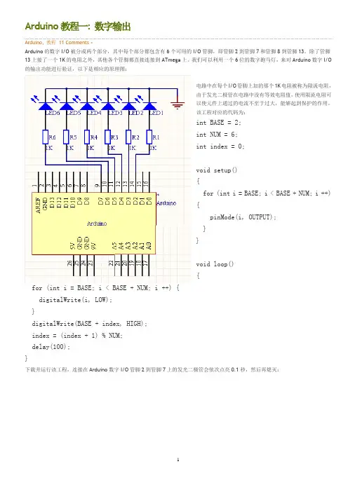
Arduino教程一: 数字输出Arduino, 教程11 Comments »Arduino的数字I/O被分成两个部分,其中每个部分都包含有6个可用的I/O管脚,即管脚2到管脚7和管脚8到管脚13。
除了管脚13上接了一个1K的电阻之外,其他各个管脚都直接连接到ATmega上。
我们可以利用一个6位的数字跑马灯,来对Arduino数字I/O 的输出功能进行验证,以下是相应的原理图:电路中在每个I/O管脚上加的那个1K电阻被称为限流电阻,由于发光二极管在电路中没有等效电阻值,使用限流电阻可以使元件上通过的电流不至于过大,能够起到保护的作用。
该工程对应的代码为:int BASE = 2;int NUM = 6;int index = 0;void setup(){for (int i = BASE; i < BASE + NUM; i ++){pinMode(i, OUTPUT);}}void loop(){for (int i = BASE; i < BASE + NUM; i ++) {digitalWrite(i, LOW);}digitalWrite(BASE + index, HIGH);index = (index + 1) % NUM;delay(100);}下载并运行该工程,连接在Arduino数字I/O管脚2到管脚7上的发光二极管会依次点亮0.1秒,然后再熄灭:这个实验可以用来验证数字I/O输出的正确性。
Arduino上一共有十二个数字I/O管脚,我们可以用同样的办法验证其他六个管脚的正确性,而这只需要对上述工程的第一行做相应的修改就可以了:int BASE = 8;SEP01Arduino教程二: 数字输入Arduino, 教程3 Comments »在数字电路中开关(switch)是一种基本的输入形式,它的作用是保持电路的连接或者断开。
Arduino从数字I/O管脚上只能读出高电平(5V)或者低电平(0V),因此我们首先面临到的一个问题就是如何将开关的开/断状态转变成Arduino能够读取的高/低电平。
ARDUINO入门及其简单实验(7例) (2)1. Arduino硬件开发平台简介 (2)1.1 Arduino的主要特色 (3)1.2 Arduino的硬件接口功能描述 (3)1.3 Arduino的技术性能参数 (4)1.4 电路原理图 (4)2. Arduino软件开发平台简介 (5)2.1 菜单栏 (6)2.2 工具栏 (6)2.3 Arduino 语言简介 (7)3. Arduino开发实例中所用部分器件 (9)1. LED简介 (9)2. 光敏电阻简介 (10)3. 直流电机简介 (10)4. 电位器简介 (10)4. Arduino平台应用开发实例 (11)4.1【实作项目一】利用LED作光敏电阻采样实验 (11)4.2【实作项目二】利用PWM信号控制LED亮度 (13)4.3【实作项目三】单键控制一只LED的亮灭 (15)4.4【实作项目四】利用PWM控制直流电机转速 (17)4.5【实作项目五】利用电位器手控LED亮度 (20)4.6【实作项目六】控制LED明暗交替 (22)4.7【实作项目七】利用光敏电阻控制LED的亮灭 (24)ARDUINO入门及其简单实验(7例)1. Arduino硬件开发平台简介Arduino硬件是一块带有USB的I/O接口板(其中包括13条数字I/O引脚,6通道模拟输出,6通道模拟输入),并且具有类似于Java、C语言的集成开发环境。
Arduino既可以扩展一些外接的电子元器件,例如开关、传感器、LED、直流马达、步进马达或其他输入、输出装置;Arduino也可以独立运行,成为一个可以跟交互软件沟通的接口装置,例如:Flash、Processing、Max/MSP、VVVV或其他互动软件。
Arduino开发环境IDE全部开放源代码,可以供大家免费下载、利用,还可以开发出更多激发人们制作欲望的互动作品。
如图1和图2所示,分别为Arduino硬件平台的实物图和电路布局图。
Arduino编程基础入门第一章:什么是Arduino?Arduino是一种开源电子平台,它由一个硬件部分和一个软件部分组成。
Arduino硬件包括一个可以编程的微控制器,用于控制各种电子元件的操作。
Arduino软件则是用于编写和上传程序到Arduino硬件的集成开发环境(IDE)。
第二章:Arduino的组成部分Arduino板上有一个微控制器,这是Arduino的核心部分。
该微控制器可以通过Arduino IDE进行编程,并通过与电脑的连接来上传程序。
Arduino板上还有一些输入和输出引脚,可以连接各种传感器和执行器。
此外,Arduino板还包括一个供电接口和一个USB 接口。
第三章:Arduino的编程语言Arduino使用一种基于C++的编程语言,它简单易学,适合初学者。
与其他编程语言相比,Arduino的编程语言具有一些专门为微控制器开发设计的特性,如控制引脚、延时函数等。
通过编写程序,可以实现与各种外部设备的交互。
第四章:Arduino的开发环境Arduino开发环境(IDE)是一个用于编写、上传和调试Arduino程序的软件工具。
它提供了一个简单直观的界面,使得编程变得容易上手。
通过IDE,用户可以创建新的程序、编辑现有的程序,并将程序上传到Arduino板上。
IDE还提供了错误检查、调试功能等。
第五章:Arduino的基本语法Arduino的基本语法与C++类似,包括函数、变量、运算符等。
在编写Arduino程序时,需要了解一些基本的语法规则,如注释、变量声明、控制结构等。
掌握这些基本语法是学习Arduino编程的重要一步。
第六章:Arduino的输入与输出Arduino的输入输出是其最基本的功能之一。
通过连接各种传感器和执行器,可以实现与外部环境的交互。
例如,可以通过连接一个温度传感器来读取环境温度,并通过连接一个LED灯来控制其亮灭。
学习如何使用不同的输入输出引脚是使用Arduino的关键。
Arduino入门版使用教程i目录介绍篇 ........................................................................ . (1)一、Arduino 基础套装介绍 (2)1、什麽是Arduino 基础套装 (2)2、元件清单 ........................................................................ (2)二、Arduino 介绍 ........................................................................ (4)1、什麽是Arduino ................................................................... . (4)2、特色描述 ........................................................................ (4)3、性能描述 ........................................................................ (4)三、Arduino C 语言介绍 ........................................................................ .. 61、关键字和符号 ........................................................................ .. (6)2、结构 ........................................................................ .. (9)3、功能 ........................................................................ (9)四、Arduino 使用介绍 ........................................................................ . (11)1、准备好你的Arduino板 (11)2、下载Arduino 开发环境 (13)3、安装USB 驱动 ........................................................................ . (13)4、连接LED 灯电路 ........................................................................ .. (17)5、打开arduino 开发环境 (18)6、打开已有程式 ........................................................................ . (19)7、编译程式 ........................................................................ . (20)8、下载程式 ........................................................................ . (23)五、面包板使用介绍 ........................................................................ .. (30)1、面包板介绍 ........................................................................ . (30)2、面包板的使用 ........................................................................ (30)ii实验篇 ........................................................................ .. (34)第一节多彩led 灯实验 ........................................................................ .. 35一、发光二极管介绍 ........................................................................ .. (35)二、简单的控制一个led 灯的闪烁实验 (39)三、广告灯效果实验 ........................................................................ .. (41)第二节蜂鸣器实验 ........................................................................ (48)一、蜂鸣器介绍 ........................................................................ .. (48)二、蜂鸣器模拟救护车警笛声音实验 (50)第三节数码管实验 ........................................................................ (54)一、数码管介绍 ........................................................................ (54)二、数码管显示数字的实验 (56)第四节按键实验 ........................................................................ (63)一、按键介绍 ........................................................................ (63)二、按键控制led 等亮灭实验 (65)三、掷骰子实验 ........................................................................ (67)第五节倾斜开关实验 ........................................................................ (74)一、倾斜开关介绍 ........................................................................ (74)二、倾斜开关控制led 灯的亮灭 (75)第六节光控声音实验 ........................................................................ (79)一、光敏电阻介绍 ........................................................................ (79)二、光控声音实验 ........................................................................ (80)第七节火焰报警实验 ........................................................................ (84)一、火焰传感器介绍 ........................................................................ (84)二、火焰报警实验 ........................................................................ (85)第八节抢答器实验 ........................................................................ (90)第九节温度报警实验 ........................................................................ (98)一、温度传感器介绍 ........................................................................ (98)iii二、温度报警实验 ........................................................................ (99)第十节红外遥控 ........................................................................ . (103)一、红外接收头介绍 ........................................................................ . (103)二、红外遥控实验 ........................................................................ . (104)介绍篇一、Arduino 基础套装介绍1、什麽是Arduino基础套装Arduino基础套装是精心为初学者设计的一款学习工具。
Arduino开发板入门教程第一章:Arduino简介Arduino是一款开源硬件平台,广泛应用于物联网、机器人和自动化领域。
它由一个简单易用的硬件开发板和一个基于Java的集成开发环境(IDE)组成。
本章将介绍Arduino的基本知识和原理。
1.1 Arduino开发板的组成Arduino开发板包含一个微控制器、一组输入输出引脚和一些其他的电子元件。
常用的Arduino型号有Arduino Uno、Arduino Nano和Arduino Mega等。
1.2 Arduino的特点和应用Arduino具有开源、低成本、易使用和可扩展的特点,使其成为广大电子爱好者和创客的首选。
它可以用于建造简单的电子装置、控制传感器、驱动电机以及与计算机进行通信等。
第二章:Arduino的基本用法本章将详细介绍Arduino的基本用法,包括设置Arduino开发环境、编写代码、上传程序以及与外部电路的连接。
2.1 Arduino开发环境的安装与设置首先,需要从Arduino官方网站上下载并安装Arduino集成开发环境(IDE)。
安装完成后,用户需要选择合适的开发板和端口。
2.2 Arduino编程基础Arduino使用一种类似C语言的编程语言。
本节将介绍Arduino编程的基本结构、语法和常用函数。
同时,还将介绍数字输入/输出、模拟输入/输出和串口通信等常用功能。
2.3 Arduino程序的上传编写好的Arduino程序需要通过USB接口将代码上传到开发板上。
本节将介绍如何将程序上传到Arduino开发板,并进行调试和测试。
2.4 Arduino与外部电路的连接Arduino开发板上有多个数字引脚和模拟引脚,可以与外部电路进行连接。
本节将介绍如何使用面包板和杜邦线将Arduino与LED、电位器、温度传感器等外部元件进行连接,并通过编写程序进行控制和读取。
第三章:Arduino的高级用法在本章中,将介绍一些Arduino的高级应用,包括使用库函数、扩展Arduino功能以及与其他设备的通信等。
Arduino入门基础教程•Arduino教程Lesson 1 -- 驱动安装及下载Blink程序 3 •Arduino教程Lesson 2 -- LED灯闪烁28 •Arduino教程Lesson 3 -- 做一个S.O.S求救信号灯35 •Arduino教程Lesson 4 -- 互动交通信号灯44 •Arduino教程Lesson 5 -- 呼吸灯56 •Arduino教程Lesson 6 -- 炫彩RGB LED61 •Arduino教程Lesson 7 -- 报警器68 •Arduino教程Lesson 8 -- 温度报警器70 •Arduino教程Lesson 9 -- 震动探测80 •Arduino教程Lesson 10 -- 感光灯87 •Arduino教程Lesson 11 --舵机初动92 •Arduino教程Lesson 12 -- 可控舵机97 •Arduino教程Lesson 13 -- 彩灯调光台102 •Arduino教程Lesson 14 -- 自制风扇105 •Arduino教程Lesson 15 -- 红外接收111 •Arduino教程Lesson 16 -- 遥控灯116 •Arduino教程Lesson 17 -- 数码管显示121全网最简单的入门教程,通俗易懂,易掌握,由易到难,循序渐进,你能学习到“传感器的感知”,”控制器的处理”,”声光电设备的反馈“等。
每篇教程结构清晰,从硬件连接——>输入代码——>代码回顾——>硬件回顾。
不同于其他教程,本教程认真讲解arduino代码释义和用法,让你真正掌握arduino编程。
Arduino教程Lesson 1 -- 驱动安装及下载Blink程序拿到了盼望已久的Arduino入门套件是不是有立马想试一试的冲动,但。
同样又面对不知如何下手的困扰呢?我们这里就从头开始教大家。
那就开始吧!STEP 1:下载Arduino IDE打开网页输入网址/en/Main/SoftwareArduino IDE老版本下载链接:/en/Main/OldSoftwareReleases进入到页面后,找到下图显示部分。
Arduino入门教程--课前准备--Arduino驱动安装及1.0 IDE菜单介绍编译器版本:Arduino 1.0实验器件:ocrobot mango控制板(Arduino兼容)一块Arduino控制板到手后,首先需要在电脑上把驱动装上,这样才可以进行各种实验。
第一步需要把Arduino IDE下载回来(IDE就是arduino的软件程序开发环境)点击下面链接进行下载:WindowsMac OS X Linux :32bit64bit下载后自己找地方解压缩放好就行了Mango在各操作系统的驱动下载:Windows:XP、WIN7 32位需要手工更新驱动,驱动在IDE目录下drivers\FTDI USB Drivers目录中,指定目录为之后自动搜索即可。
WIN7 64位,WIN8自动在线更新驱动即可。
苹果Mac OS X:... lDriver_v2_2_18.dmgLinux:Ubuntu下自动识别驱动,使用管理员权限启动IDE即可识别到端口。
然后将买回来的arduino拆了包装,使用方头usb数据线连接到电脑,本文以win7 32位为例,会出现识别到新硬件显示。
然后会开始查找系统内驱动。
如果没有找到驱动,会显示这个画面。
这时,需要在开始菜单,“计算机”上面点右键,点“属性”。
然后点击设备管理会看到打了感叹号的未识别硬件在未识别硬件上点右键,点击“属性”,选择更新驱动程序软件。
选择浏览计算机以查找驱动程序软件然后目录选择你下载好的arduino1.0所在目录的drivers目录注意,如果您的计算机提示无法找到驱动,需要将目录进一步定位到\drivers\FTDI USB Drivers即可点击下一步,就可以安装好驱动了。
安装好驱动后,就可以显示是COM几端口,我这里显示的是COM14端口。
========分割线下面为扩展阅读========接着我们介绍下Arduino的IDE界面,以Arduino 1.0 IDE为例,首先进入软件目录。
Arduino Smart Robot Car KitUser GuideV1.0 04.2017Table of Contents1. Introduction (3)2. Assembly (4)2.1 Arduino Uno R3 (4)2.2 HC-SR04 Ultrasonic Sensor Module with Bracket / Holder (5)2.3 L293D Motor Drive Expansion Board for Arduino (7)2.4 SG90 9g micro small servo motor (8)2.5 2WD Driver Motor Encoder Robot Smart Car Chassis Kits (9)3. Pin Definition (10)4. Installation (11)4.1 Installation of the Components (11)4.2 Installation of the Car (13)5. Start Programing (20)1.IntroductionThe UCTRONICS smart robot car kit is a flexible vehicular kit particularly designed for education, competition and entertainment purposes.The kit has an intelligence built in so that it guides itself whenever an obstacle comes ahead of it. An Arduino development is used to achieve the desired operation. With the help of a small servo motor, it scans the area left and right in order to find the best way to turn. An ultrasonic sensor unit is used to detect any obstacle ahead of it that sends a command to the Arduino Board. Depending on the input signal received, the Arduino microcontroller redirects the robot to move in an alternate direction by appropriately actuating the motors interfaced to it through a motor driver IC.When all the necessary components are getting together, a robot car comes up!A robot is a machine that can perform some task automatically or with guidance. Robotics is generally a combination of computational intelligence and physical machines (motors). Due to their high level of performance and reliability, the robot get the splendid popularity in our daily life.Come up, let’s go into a Robot World !1.1 Packing list➢1pcs Arduino UNO R3 Board➢1pcs HC-SR04 Ultrasonic Sensor Module➢1pcs Holder for HC-SR04➢1pcs L293D Motor Drive Expansion Board➢1pcs 9g micro servo motor➢1pcs servo motor Bracket➢Some cable end pin header as gift➢1set Car Chassis Kits:●2pcs 65mm tire Wheels●2pcs Geared Motors (1:48)●2pcs Speed Encoders●1pcs Universal Wheel●1pcs Battery Box●1pcs Car Chassis●1pcs Switch●Screws+ Nuts2. Assembly2.1 Arduino Uno R3This is the new Arduino Uno R3. In addition to all the features of the previous board, the Uno now uses an ATmega16U2 instead of the 8U2 found on the Uno (or the FTDI found on previous generations). This allows for faster transfer rates and more memory. No drivers needed for Linux or Mac (.inf file for Windows is needed and included in the Arduino IDE),and the ability to have the Uno show up as a keyboard, mouse, joystick, etc.The Uno R3 also adds SDA and SCL pins next to the AREF. In addition, there are two new pins placed near the RESET pin. One is the IOREF that allow the shields to adapt to the voltage provided from the board. The other is a not connected and is reserved for future purposes. The Uno R3 works with all existing shields but can adapt to new shields which use these additional pins.Note: The Arduino Uno R3 requires the Arduino 1.0 drivers folder in order to install properly on some computers. We have tested and confirmed that the R3 can be programmed in older versions of the IDE. However, the first time using the R3 on a new computer, you will need to have Arduino 1.0 installed on that machine. If you are interested in reading more about the changes to the IDE, check out the official Arduino 1.0 Release notes!2.1.1 Specifications➢Microcontroller: ATmega328➢Operating Voltage: 5V➢Input Voltage (recommended): 7-12V➢Input Voltage (limits): 6-20V➢Digital I/O Pins: 14 (of which 6 provide PWM output)➢Analog Input Pins: 6➢DC Current per I/O Pin: 40 mA➢DC Current for 3.3V Pin: 50 mA➢Flash Memory: 32 KB (ATmega328) of which 0.5 KB used by bootloader➢SRAM: 2 KB (ATmega328)➢EEPROM: 1 KB (ATmega328)➢Clock Speed: 16 MHz2.2 HC-SR04 Ultrasonic Sensor Module with Bracket / HolderThe HC-SR04 ultrasonic sensor module for Arduino is used for obstacle detection. Ultrasonicsensor transmits the ultrasonic waves from its sensor head and again receives the ultrasonic waves reflected from an object.Ultrasonic sensor general diagram2.2.1 Working PrincipleThe ultrasonic sensor emits the short and high frequency signal. These propagate in the air at the velocity of sound. If they hit any object, then they reflect back echo signal to the sensor. The ultrasonic sensor consists of a multi vibrator, fixed to the base. The multi vibrator is combination of a resonator and vibrator. The resonator delivers ultrasonic wave generated by the vibration. The ultrasonic sensor actually consists of two parts; the emitter which produces a 40kHz sound wave and detector detects 40 kHz sound wave and sends electrical signal back to the microcontroller.Ultrasonic working principleThe ultrasonic sensor enables the robot to virtually see and recognize object, avoid obstacles, measure distance. The operating range of ultrasonic sensor is 2 cm to 450 cm.2.2.2 Specification➢Working Voltage: 5V(DC)➢Static current: < 2mA➢Output signal: Electric frequency signal➢Output Voltage: 0-5V➢Sensor angle: <= 15 degrees➢Detection distance: 2cm-450cm➢High precision: Up to 0.3cm➢Input trigger signal: 10us TTL impulse➢Echo signal: output TTL PWL signal➢Mode of connection: VCC, trig (T), echo, GND➢Using method:(1)Supply module with 5V(2)Output will be 5V while obstacle in range, otherwise it will be 0V.➢Item size (mm): 44x20x152.2.3 Wiring diagram:HC-SR04 Ultrasonic Sensor Module ArduinoVCC5VTrig A4Echo A5GND GND2.3 L293D Motor Drive Expansion Board for ArduinoThis is a commonly used DC motor drive module, using L293D chip with small current DC motor driver. The pins are made compatible with Arduino which is easy to use.2.3.1 Specification➢ 2 connections for 5V servos connected to the Arduino's high-resolution dedicated timer - no jitter➢Up to 4 bi-directional DC motors with 4 PWM speed regulation➢Up to 2 stepper motor control, single / double step control, staggered or microstepping and rotation angle control➢ 4 H-Bridges: L293D chipset provides 0.6A per bridge (1.2A peak) with thermal shutdown protection, 4.5V to 36V➢Pull down resistors to keep motors in the state of rest during power-up➢Large terminal terminals make wiring easier (10 - 22AWG)➢With Arduino reset button➢The 2 terminals are connected to the external power supply terminals to ensure the separation of the logic and the motor drive powerVoltage DC 3V DC 5V DC 6VCurrent100MA 100MA 120MAReduction rate48:1RPM (with tire)100 190 240Tire Diameter66mmCar Speed (M/minute)20 39 48Motor Weight (g)50Motor Size (mm)70x22x18mmNoise<65dB2.4 SG90 9g micro small servo motorSG90 9g micro small servo motor is the main source of controlling action of the remote-control model. The module is widely applied in the field of fixed wing, helicopter, gliding, small robot, manipulator model.2.4.1 Specification➢Size (mm): 23x12.2x29➢Torsional moment: 1.5kg/cm➢Working voltage: 4.2-6V➢Temperature range : 0 ℃~55 ℃➢Operating speed: 0.1 seconds /60 degree➢Dead band width: 10 microseconds2.5 2WD Driver Motor Encoder Robot Smart Car Chassis KitsWith the car platform, adding micro-controller (such as Arduino) and sensor modules, then program it, a robot car comes up.All the module interface has been modified with XH2.54 ports as to make it much easier and convenient to assemble the car and reduce the chances for errors.2.5.1 Specification➢The car is the tachometer encoder➢With a 4 AA battery box➢Gear Motor reduction radio: 48:1➢Apply in distance measurement, velocity3. Pin DefinitionArduino UNO R3 BoardL293D Motor Drive Expansion Board4. Installation4.1 Installation of the Components Step 1Step 2Step 3Step 44.2 Installation of the Car Step 1Step 2Step 4Step 6Step 8Step 10Step 125. Start ProgramingFor examples and documentation, please visit:https:///UCTRONICS/Smart-Robot-Car-Arduino.gitIf any problems or suggestions for the tutorial or the robot car, please feel free to contact us by following ways:Skype: fpga4uTel: +86 025 ********Website: Email:*******************。