隔离开关Switches(abb断路器选型和技术参数)
- 格式:xls
- 大小:163.00 KB
- 文档页数:10
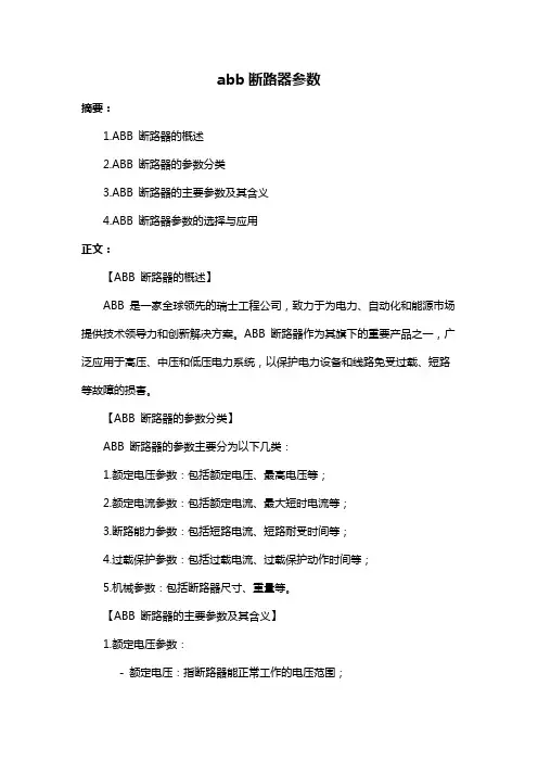
abb断路器参数摘要:1.ABB 断路器的概述2.ABB 断路器的参数分类3.ABB 断路器的主要参数及其含义4.ABB 断路器参数的选择与应用正文:【ABB 断路器的概述】ABB 是一家全球领先的瑞士工程公司,致力于为电力、自动化和能源市场提供技术领导力和创新解决方案。
ABB 断路器作为其旗下的重要产品之一,广泛应用于高压、中压和低压电力系统,以保护电力设备和线路免受过载、短路等故障的损害。
【ABB 断路器的参数分类】ABB 断路器的参数主要分为以下几类:1.额定电压参数:包括额定电压、最高电压等;2.额定电流参数:包括额定电流、最大短时电流等;3.断路能力参数:包括短路电流、短路耐受时间等;4.过载保护参数:包括过载电流、过载保护动作时间等;5.机械参数:包括断路器尺寸、重量等。
【ABB 断路器的主要参数及其含义】1.额定电压参数:- 额定电压:指断路器能正常工作的电压范围;- 最高电压:指断路器能承受的最高电压,超过该值可能会损坏断路器。
2.额定电流参数:- 额定电流:指断路器在正常工作条件下允许通过的最大电流;- 最大短时电流:指断路器在短时间内允许通过的最大电流,超过该值可能会损坏断路器。
3.断路能力参数:- 短路电流:指在短路条件下,断路器能迅速切断的电流;- 短路耐受时间:指断路器在短路条件下能承受的时间,超过该时间可能会损坏断路器。
4.过载保护参数:- 过载电流:指在过载条件下,断路器能检测到的电流;- 过载保护动作时间:指在过载条件下,断路器从检测到过载到切断电源的时间。
5.机械参数:- 断路器尺寸:指断路器的长、宽、高等物理尺寸;- 重量:指断路器的质量。
【ABB 断路器参数的选择与应用】选择ABB 断路器时,需根据实际应用场景和电力系统的需求,综合考虑上述参数,以确保断路器能满足保护电力设备和线路的要求。
在实际应用中,应根据以下原则选择ABB 断路器参数:1.确保断路器的额定电压参数与电力系统的电压等级相匹配;2.根据电力系统的最大负载电流和短时电流选择合适的额定电流参数;3.根据电力系统的短路电流和短路耐受时间选择合适的断路能力参数;4.根据电力系统的过载电流和过载保护动作时间选择合适的过载保护参数;5.根据安装空间和承重能力选择合适的机械参数。
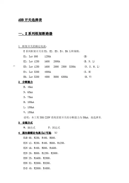
1 ABB开关选择表一、E系列框架断路器1 框架开关的额定电流:E系列框架开关有E1、E2、E3、E4、E6五种规格。
E1:Iu= 800 1250A (B)E2:Iu= 1250 1600 2000A (B、N、L)E3:Iu= 1250 1600 2000 2500 3200A (N、S、H、L) E4:Iu= 3200 4000A (S、H)E6:Iu= 3200 4000 5000 6300A (H、V)2 分断能力B:40kAN:63kAS:75kAH:100kAL:130kAV:150kA说明:本工程380/220V系统需要开关的分断能力为50kA,故选择N。
3 安装方式W:抽出式 F:固定式4 脱扣器额定电流(Ir)可选:(A)E1B 08:R250, R400, R800。
E2N 12:R250,R400,R800,R1250。
E2N 16:R400,R800,R1600。
E2N 20:R800,R1250,R2000。
E3N 25:R1600,R2500。
E3N 32:R2000,R3200。
E4S 40:R2000,R4000。
2 5 微处理器保护脱扣器功能:1) PR111/P-LI:拨码式两段保护PR111/P-LSI:拨码式,三段保护PR111/P-LSIG:拨码式,四段保护其中:L、I为可调。
2) PR112/P/LSI:数显式,三段保护PR112/P-LSIG:数显式,四段保护3) PR112/PO/LSI:数显式,三段保护,带对话、遥控、通讯系统PR112/PO/LSIG:数显式,三段保护,带对话、遥控、通讯系统6 微处理器保护脱扣器整定范围:对于PR111/P保护脱扣器:过载长延时整定(L):(0.4、0.5、0.6、0.7、0.8、0.9、0.95、1.0)In级差为0.1。
短路短延时整定(S):(OFF,1、2、3、4、6、8、10)In短路瞬时整定(I):(OFF,1.5、2、4、6、8、10)In对于PR112/P、PR112、PD保护脱扣器:过载长延时整定(L):(0.4……1.0)In 级差为0.01。
abb开关参数
ABB开关参数是电气行业中常见的一种开关,其使用范围极广,
可以应用于各种类型的建筑和工程项目中。
在使用ABB开关参数之前,我们需要了解其基本的构造和使用方法,以便确保其正常的工作和使
用寿命。
第一步:了解ABB开关参数的基本参数和特点
ABB开关参数具有许多不同的设计和特点,其中最为重要的参数
包括额定电压、额定电流、短路电流承受能力等等。
在了解ABB开关
参数的参数之前,我们需要确认并确定各种不同的应用场景和需要满
足的安全标准等因素。
第二步:ABB开关参数的安装和维护
在安装ABB开关参数之前,需要对其进行检查,确保其符合各种
不同的安全标准和要求。
安装过程应遵循严格的程序和规范,防止在
安装过程中发生任何意外事故。
ABB开关参数还需要进行定期维护,以确保其的正常运行和有效性。
维护包括电气接线和上下手柄联锁检查等,需要定期进行检查和更换。
第三步:ABB开关参数的故障排除和应急措施
当ABB开关参数发生故障或故障时,我们需要采用相应的应急措施,以确保其的正常运行和作业效率。
应急措施包括检查电缆的连接、进行开断机器之间的测量、检查电源电压是否正常,还需要进行故障
定位和更换故障部件等,以确保ABB开关参数正常使用。
总之,ABB开关参数是电气行业中常用的一种开关,在使用之前
需要进行详细的说明和确认,以确保其能够正常工作和使用。
对其进
行安装、维护和故障排除等也需要遵循相应的规范和标准,以确保其
在工作过程中的安全和高效性。
abb断路器参数(原创实用版)目录1.ABB 断路器概述2.ABB 断路器型号大全3.如何查看 ABB 断路器型号参数4.ABB 断路器的应用范围5.结束语正文ABB 断路器是一种用于保护电路和设备的重要元件,它可以在电路中断路、过载和短路等情况下,及时切断电源,防止设备受到损坏。
ABB 作为全球 500 强企业,其生产的断路器种类繁多,覆盖了从微型断路器到高分断能力的塑壳、空气断路器的各个领域。
一、ABB 断路器型号大全ABB 断路器的型号大全包括以下几个框架:1.Emax2:适用于配电系统的万能式断路器。
2.Xtmax:适用于工业应用的塑壳断路器。
3.Formula:适用于住宅和商业建筑的微型断路器。
4.Tmax:适用于电力系统的空气断路器。
5.Sh200 和 S200:适用于低压断路器的微型断路器。
二、ABB 断路器型号参数怎么看想要了解 ABB 断路器的型号参数,可以从以下几个方面入手:1.额定电压:指断路器正常工作时,系统的额定线电压。
这是断路器的标称电压,应能保持在这一电压的电力系统中使用,最高工作电压可超过额定电压 15%。
2.额定电流:指断路器在规定使用和性能条件下可以长期通过的最大电流。
当额定电流长期通过高压断路器时,其发热温度不应超过国家标准中规定的数值。
3.额定短路开断电流:指断路器在短时间内能够安全切断的最大电流。
三、ABB 断路器的应用范围ABB 断路器广泛应用于工业、住宅、商业建筑、电力系统等领域,为电路提供可靠的保护。
其产品性能稳定,质量可靠,得到了全球用户的认可。
总之,ABB 断路器作为全球知名品牌的断路器产品,无论从型号、参数还是应用范围上,都展现出了强大的实力。
abb微型隔离开关参数含义随着电力行业的发展,ABB微型隔离开关作为一种重要的电气设备,被广泛应用于电力系统中。
了解ABB微型隔离开关的参数含义对于正确选择和使用该设备至关重要。
本文将对ABB微型隔离开关的参数含义进行详细解析。
首先,ABB微型隔离开关的参数包括额定电压、额定电流、额定短路开断电流和额定短路关合电流。
额定电压是指设备能够正常工作的电压范围。
在选择ABB微型隔离开关时,需要根据实际使用场景的电压要求来确定合适的额定电压。
额定电流是指设备能够承受的最大电流。
在电力系统中,电流是一个重要的参数,因此选择合适的额定电流对于保证设备的正常运行至关重要。
额定短路开断电流是指设备在短路情况下能够安全地切断电流的能力。
短路是电力系统中常见的故障,因此选择具有足够额定短路开断电流的ABB微型隔离开关可以有效地保护电力系统的安全运行。
额定短路关合电流是指设备在短路情况下能够安全地接通电流的能力。
与额定短路开断电流类似,额定短路关合电流也是保证电力系统安全运行的重要参数。
除了以上参数,ABB微型隔离开关还有一些其他的参数需要了解,如额定绝缘水平、额定频率和额定操作次数。
额定绝缘水平是指设备在正常工作条件下的绝缘能力。
绝缘是电力系统中防止电流泄漏和电弧产生的重要手段,因此选择具有合适额定绝缘水平的ABB微型隔离开关可以提高电力系统的安全性。
额定频率是指设备能够正常工作的频率范围。
在电力系统中,频率是一个重要的参数,因此选择合适的额定频率对于保证设备的正常运行至关重要。
额定操作次数是指设备能够正常工作的操作次数。
在实际使用中,ABB微型隔离开关需要经常进行开关操作,因此选择具有足够额定操作次数的设备可以提高设备的使用寿命。
综上所述,了解ABB微型隔离开关的参数含义对于正确选择和使用该设备至关重要。
在选择ABB微型隔离开关时,需要根据实际使用场景的要求来确定合适的额定电压、额定电流、额定短路开断电流和额定短路关合电流。
abb隔离开关说明书一、产品概述abb隔离开关是一种用于切断和隔离电路的电气设备。
本产品设计精巧,安装方便,具有高可靠性和安全性能,可广泛应用于低压配电系统中。
本说明书将详细介绍abb隔离开关的特点、技术参数、安装要求及使用方法,方便用户正确使用该设备并确保电气设备的正常运行。
二、产品特点1. 高可靠性:abb隔离开关采用优质的导电材料和高级绝缘材料制造,确保其在长时间使用过程中不易老化和损坏。
2. 安全可靠:该设备具备良好的隔离性能,能够有效切断电路并保护人身安全。
同时,abb隔离开关在设计过程中考虑了防误操作的因素,有效避免了因误操作导致的电击事故。
3. 操作简便:abb隔离开关具有简洁明了的操作界面,用户只需按照说明书操作即可完成开关的开启和切换操作。
4. 节能环保:本产品在正常使用过程中无需外部能源供应,不会产生额外的能源消耗,符合节能环保要求。
三、技术参数名称:abb隔离开关额定电压:AC220V/380V额定电流:10A/20A/32A/63A工作温度:-20℃~+40℃绝缘电阻:≥100MΩ机械寿命:10000次防护等级:IP65四、安装要求1. 安装位置:abb隔离开关应安装在通风良好、干燥的室内环境中,位置选定要远离易燃易爆物品和腐蚀性物质,以免影响设备的正常运行。
2. 安装固定:请使用符合国家标准的配件进行固定,并确保设备不会因外界震动而脱落或松动。
3. 电源连接:在连接电源之前,请务必确认电源已切断,并按照符合国家相关标准的接线方法进行连接。
接线过程需注意导线的规格和截面积要符合设备的要求,确保电气连接的可靠性。
4. 接地保护:在安装abb隔离开关的过程中,请确保设备的接地线与地线连接牢固可靠,以提供必要的电气保护。
五、使用方法1. 开关动作:通过操作装置将abb隔离开关切换至所需位置。
开关切换过程中,请确保操作装置与开关本体之间的连接稳固,并避免过度用力造成损坏。
2. 检查开关状态:在操作abb隔离开关后,请检查开关的位置是否与所需状态一致,以确保电路的安全隔离。
标题:abb隔离开关选型
一:触器适用于建筑业和工业领域,如:电机控制、保暖和通风、空调、水泵、提升设备、照明和校正功率因数等。
ABB接触器的规格包括4和5.5KW的微型接触器、高达400kW的接触器组(AC3),建筑用接触器(家用和工业用),拍合式接触器,热过载继电器和电子继电器,以及完整的附件,确保选择灵活性和满足客户需求,公司制造工厂位于海西经济区的核心----美丽的鹭岛厦门。
二:ABB断路器可为快速恢复运行条件(防止故障发生),并提供最好的解决方案,同时可提供最优的电气安装保护。
从微型断路器到高分断能力的塑壳/空气断路器
三:小型断路器多级:ABB断路器可为快速恢复运行条件(防止故障发生),并提供最好的解决方案,同时可提供最优的电气安装保护。
从微型断路器到高分断能力的塑壳/空气断路器
四:变频器主要用于控制和调节三相交流异步电机的速度,并以其稳定的性能、丰富的组合功能、高性能的矢量控制技术、低速高转矩输出、良好的动态特性及超强的过载能力,在变频器市场占据
着重要的地位。
施耐德公司断路器产品断路器C65漏电保护附件Vigi C65电磁式漏电保护附件C32H-DC直流断路器EA9AH交流微断路器EA9AN交流微断路器C32N空开被低压断路器OSM系列替代如:OSM32N/C1ANSX塑壳断路器带TM-D热磁脱扣单元ABB公司断路器产品ISOMAX系列塑壳断路器E系列相关产品空气断路器-Emax电子脱扣器- PR121/P、PR122/P及PR123/PEmax系列空气断路器,配备了先进的基于微处理器技术的脱扣器:PR121/P、PR122/P及PR123/P。
基本型PR121/P提供整套的标准保护功能和一个完善友好的用户界面。
PR122/P和PR123/P 采用模块化结构概念,根据设计和客户的要求,可实现一套集完善的保护、准确的测量、信号指示或对话功能为一体的断路器。
电子脱扣器的主要特点:•运行时不需外部电源•采用微处理器技术•精密度高•对电流的真实值R.M.S反应灵敏•具有故障原因指示以及脱扣数据记录•各型号的脱扣器可互换•中性线的设定情况:- 可设定为OFF或相电流的50%、100%或200%,应用于E1、E2、E3、E4/f、E6/f,以及带外部中性线保护的E4和E6-可设定为OFF或相电流的50%,应用于E4和E6空气断路器-Emax X1 技术数据一览表系列产品的共同特性规格空气断路器-Emax X1电子脱扣器- PR331/P、PR332/P主要特点:•运行时不需外部电源•使用微处理器技术•精密度高•对电流的真实值R.M.S反应灵敏•故障原因指示以及脱扣数据记录•脱扣器可互换保护功能:过载保护- 具有反时限长延时脱扣特性选择性短路保护- 具有反时限或定时限短延时脱扣特性塑壳断路器-Tmax技术数据一览表塑壳断路器-Tmax电子脱扣器- PR331/P、PR332/P 电子脱扣器- PR231/P、PR232/P塑壳断路器-Tmax剩余电流脱扣器C221 和RC222 剩余电流脱扣器RC221 和RC222 适用于3 / 4 极固定式T1、T2 和T3 断路器。
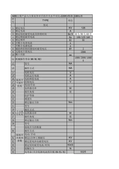
隔离开关主要技术参数隔离开关是电力系统中常用的重要设备,用于隔离和切断电路。
它具有多种技术参数,下面将对其主要技术参数进行详细介绍。
1. 额定电压(Rated Voltage)额定电压是指隔离开关能够正常工作的最高电压值。
根据不同的使用场景和要求,隔离开关的额定电压可以有多种规格,常见的有220V、380V、110kV等。
2. 额定电流(Rated Current)额定电流是指隔离开关能够承载的最大电流值。
根据不同的电路负载需求,隔离开关的额定电流也会有所不同,常见的有10A、20A、630A等。
3. 短时耐受电流(Short-time Withstand Current)短时耐受电流是指隔离开关能够在短时间内承受的最大电流值。
在电力系统中,由于各种原因可能会出现短路等故障,隔离开关需要能够承受相应的短时耐受电流,以确保系统的安全运行。
4. 动作次数(Operating Times)动作次数是指隔离开关的使用寿命。
隔离开关在正常运行过程中需要进行开关操作,每次开关操作都会导致一定的磨损,因此需要规定隔离开关的动作次数,以保证其可靠性和使用寿命。
5. 绝缘水平(Insulation Level)绝缘水平是指隔离开关的绝缘性能。
隔离开关在工作时需要隔离电路,避免电流的传导,因此需要有良好的绝缘性能。
绝缘水平一般通过绝缘电阻和耐压能力来衡量,常见的绝缘水平有1kV、3kV、10kV等。
6. 防护等级(Protection Level)防护等级是指隔离开关的防护性能。
隔离开关在使用过程中需要能够防护外部环境的侵入,以保证其正常工作。
防护等级一般通过IP 码来表示,常见的有IP20、IP54等。
7. 防爆等级(Explosion-proof Level)防爆等级是指隔离开关的防爆性能。
在某些特殊场合,如化工厂、石油化工等场所,存在爆炸危险,因此需要隔离开关具备一定的防爆能力,以确保设备运行的安全性。
防爆等级一般通过防爆标志来表示,如ExdⅡBT4。
abb隔离开关选型手册ABB是一家全球知名的电气设备制造商,其隔离开关产品应用广泛,包括电力输配、建筑、工业自动化等领域。
由于市场上有许多不同类型和规格的ABB隔离开关产品,选择合适的产品对于设备的安全性和性能至关重要。
本文将向读者介绍ABB隔离开关的选型指南,帮助读者了解如何选择适合自己需求的ABB隔离开关产品。
首先,选择ABB隔离开关产品前应明确自己的需求。
隔离开关主要用于切断电源和设备之间的电力连接,确保设备在维修和维护期间的安全。
因此,需要注意以下几个方面的要素:1.负载类型:ABB隔离开关适用于不同类型的负载,如电机、变压器、电动机和照明设备等。
在选择时需根据负载类型来确定产品型号和额定电流。
2.额定电流:ABB隔离开关的额定电流范围广泛,从几安培到几千安培不等。
确认所需额定电流后,在选购时要确保选到满足负载需求的额定电流。
3.工作环境:根据使用环境的不同,可以选择不同等级的ABB隔离开关,如室内或室外用、防尘防水等级要求。
4.可靠性和安全性:ABB隔离开关的可靠性和安全性对于设备的正常运行至关重要。
因此,在选型时要选择有良好声誉的供应商,确保产品经过认证,并提供相关安全保障。
其次,了解不同类型的ABB隔离开关产品。
ABB隔离开关产品种类繁多,包括断路器、刀闸、负荷刀闸等。
这些产品在结构、功能和应用上有所区别,需要根据具体需求选择合适的产品。
1.断路器(Circuit Breaker):ABB断路器是一种多功能开关设备,既可用作隔离开关,又可用作过载和短路保护。
它具有快速切断、重载保护和过电流保护等功能。
2.刀闸(Knife Switch):ABB刀闸是一种简单可靠的开关设备,主要用于切断电源。
它采用刀片与触头接触来切断电路,适用于低压负载。
3.负荷刀闸(Load Break Switch):ABB负荷刀闸是一种隔离开关,可用于切断潮湿环境下的电路。
它具有手动操作、分段保护和电动操作等功能。
—INTERNALELDS, 3408 INDOOR PRODUCTSNAL- MV indoor air insulated switch-disconnector Products features and applications—AgendaIntroduction to MV indoor air insulated switches Design and operation principlesDrivesAccessoriesApplicationsSummary—Introduction to MV switch-disconnectorsWhat is switch-disconnector•Switch-disconnectors are designed to open and close circuitsunder normal current conditions•Cannot interrupt under fault conditions •Able to close into a fault up to its fault-close current ratingOverviewNAL/NALF (IEC)VersaRupter (USA)NAL CSA (Canada)Portfolio –indoor air insulated switch-disconnectorsIEC standards –12-36 kV •Rated current:…1250A •STC: …31.5 kA (1s)•Making: …67 kA peakANSI standard–4.76-38 kV•Rated current: …1200A•STC: …40 kA (3s)•Fault making: (61)kA RMS CSA 22.2 compliance –4.16-34.5 kV •Rated current:…1200A •STC:…25 kA (3s)•Fault close:…40 kA RMSPortfolio – indoor air insulated switch-disconnectors NAL/NALF (IEC)-highlightsIEC standards–12-36 kV•Rated current:…1250A •STC: …31.5 kA (1s)•Making: …67 kA peak •well known around the globe, with more than 800,000 switches delivered•unique design that extinguishes electric arcs and enables high switching capacity•an attractive solution as a key breaking element for applications in enclosed switchgear and transformer compact substations.•In combination with ABB type CEF current limiting fuses, NALF switch-fuse combination ensures control over the full range of overload and short-circuit current •NAL/NALF switch-disconnector can be used in all medium voltage primary and secondary distribution systems like industrial workshops, factories, prefabricated substations, CSS, solar and wind grid connection stations.Applications–Line switch disconnector in MV networks:•Interrupt load, sectionalize, isolate downstream equipment –Industrial and commercial–Switching and protection for distribution transformers when combined with fuses (IEC 62271-105)–NAL switch capable of:•1000 mechanical no load operations•Up to 100 electrical operations at full rated current–Service conditions – indoor, with ambient air temp. within -40 and up to 55 °C•Standard NAL/F is addressed for normal service conditions (Design Class 0)•NAL –H/NALF-H is suitable for severe operating conditions (Design Class 2) acc. to IEC 62271-304:2008-05What are the applications?NAL design configurations–Pole distance•12 kV – 150 mm, 170 mm and 210 mm,•17.5 kV – 170 mm and 210 mm,•24 kV – 235 mm and 275 mm,•36 kV – 360mm,–Rated currents•400, 630 and 1250 A at 12 kV,•400, 630 A at 17.5/24 kV,•630/800/1000 A at 36 kV,–STC: up to 31.5 kA (1s)–Making capacity: up to 67 kA (peak)–E3 electrical class performance: NAL/NAL-H 12 630A and NAL/NAL-H 17/24 630ASmart choice of available product basic variants withstandard and severe application variantsNAL switches comply with recent IEC 62271-1 and IEC 62271-103 standard NALF switch-fuse combination comply with recent IEC 62271-1 and IEC62271-105 standardsTypes designation1) Only for versions with A mechanism and fuse release.2) The “EB” type of free standing earthing switch, contains the following free standingearthing switches for 36 kV only: EB (free standing earthing switch for separateinstallation), EBS ( EB 36 on pivot side NAL), EBSU ( EB 36 on opening side NAL),EBF (EB 36 on pivot side NAL), EBFU (EB 36 on opening side NALF). EBS, EBSU, EBF,EBFU names are used in product configurator and as configuration description only.3) For 36 kV only4) For 12 kV only5) For left hand side operation shaft extension must be used6) The earthing switch is normally delivered without mechanical interlocking, whichmust be specified separately.7) The “E” type of earthing switch, contains the following earthing switches:EF (earthing switch attached to fuse-base) and EI (earthing switch attachedto fuse-base and located under fuse-links). EF and EI names are used in productconfigurator and as configuration description only.8) For 12, 17.5 and 24 kV9) K for 12&36 kV; K17 for 17.5 kV; K24 for 17.5&24 kV10) A for 12&36 kV; A17 for 17.5 kV; A24 for 17.5&24 kV—Design and operation principles NALModular design for easy adaptationNAL/F design principlesThe NAL can be easily configured in line with specific application requirements–Main configurable components•Single or double spring mechanism•Auxiliary contacts for switch and earthing switch•Motor drives – shaft and front mounted•Blocking and tripping coils•Fuse base with or w/o fuse tripping system – upper/lower•Earthing switch – upper/lower•Mechanical interlocks•Blown fuse indicatorModular design for easy adaptationNAL/F design principlesThe NAL can be easily configured in line with specific application requirements–Main configurable components•Single or double spring mechanism•Auxiliary contacts for switch and earthing switch•Motor drives – shaft and front mounted•Blocking and tripping coils•Fuse base with or w/o fuse tripping system – upper/lower•Earthing switch – upper/lower•Mechanical interlocks•Blown fuse indicatorModular design for easy adaptationThe NAL can be easily configured in line with specific application requirements–Main configurable components•Single or double spring mechanism•Auxiliary contacts for switch and earthing switch•Motor drives – shaft and front mounted•Blocking and tripping coils•Fuse base with or w/o fuse tripping system – upper/lower •Earthing switch – upper/lower•Mechanical interlocks•Blown fuse indicatorNAL/F design principlesModular design for easy adaptationNAL/F design principlesThe NAL can be easily configured in line with specific application requirements–Main configurable components•Single or double spring mechanism•Auxiliary contacts for switch and earthing switch•Motor drives – shaft and front mounted•Blocking and tripping coils•Fuse base with or w/o fuse tripping system – upper/lower•Earthing switch – upper/lower•Mechanical interlocks•Blown fuse indicatorModular design for easy adaptationNAL/F design principlesThe NAL can be easily configured in line with specific application requirements–Main configurable components•Single or double spring mechanism•Auxiliary contacts for switch and earthing switch•Motor drives – shaft and front mounted•Blocking and tripping coils•Fuse base with or w/o fuse tripping system – upper/lower•Earthing switch – upper/lower•Mechanical interlocks•Blown fuse indicatorModular design for easy adaptationNAL/F design principlesThe NAL can be easily configured in line with specific application requirements–Main configurable components•Single or double spring mechanism•Auxiliary contacts for switch and earthing switch•Motor drives – shaft and front mounted•Blocking and tripping coils•Fuse base with or w/o fuse tripping system – upper/lower•Earthing switch – upper/lower•Mechanical interlocks•Blown fuse indicatorModular design for easy adaptationNAL/F design principlesThe NAL can be easily configured in line with specific application requirements–Main configurable components•Single or double spring mechanism•Auxiliary contacts for switch and earthing switch•Motor drives – shaft and front mounted•Blocking and tripping coils•Fuse base with or w/o fuse tripping system – upper/lower•Earthing switch – upper/lower•Mechanical interlocks•Blown fuse indicatorModular design for easy adaptationNAL/F design principlesThe NAL can be easily configured in line with specific application requirements–Main configurable components•Single or double spring mechanism•Auxiliary contacts for switch and earthing switch•Motor drives – shaft and front mounted•Blocking and tripping coils•Fuse base with or w/o fuse tripping system – upper/lower•Earthing switch – upper/lower•Mechanical interlocks•Blown fuse indicatorModular design for easy adaptationNAL/F design principlesThe NAL can be easily configured in line with specific application requirements–Main configurable components•Single or double spring mechanism•Auxiliary contacts for switch and earthing switch•Motor drives – shaft and front mounted•Blocking and tripping coils•Fuse base with or w/o fuse tripping system – upper/lower•Earthing switch – upper/lower•Mechanical interlocks•Blown fuse indicatorModular design for easy adaptationNAL/F design principlesThe NAL can be easily configured in line with specific application requirements–Main configurable components•Single or double spring mechanism•Auxiliary contacts for switch and earthing switch•Motor drives – shaft and front mounted•Blocking and tripping coils•Fuse base with or w/o fuse tripping system – upper/lower•Earthing switch – upper/lower•Mechanical interlocks•Blown fuse indicatorNAL with ES design schemePiston w. rodPost insulatorES main contactES kniveHollow insulatorArch chuteMain contactCurrent kniveArching kniveMain shaftFrameES shaft ES frameOctober 20, 2023Slide21NAL/VR design principles (1)Two active breaking systems during interruption process–Gas blast (current dependent)•Whenever high overload current must be interrupted the high temperature appears inside arcing chamber, that activates intensive gas molecules release process –Air blast (current independent)•Whenever NAL opens, air has been compressed inside cylinder of hollow insulator by moving up the piston, that is mechanically interlocked with main shaft •The compressed air is blown througharcing chamber to support interruption of small load currentsUnique combination of two arc extiguinishing systemsFunction – switch in closed position(1) Closed position•Main and arcing knives are closed•Current floats through main knivesFunction – switch opening(2)Opening process•Main knives open first•Current load stays on arcing knives only•Arcing knives open and break load currentFunction – switch in open position(3) Completely opened•All knives are disconnected•Visible insulation breakFunction – switch closing(4)Closing process•Main knives close first•Arcing knives close•Load current is connected toterminalsFunction – switch in closed position(5/1) Closed position•Main and arcing knives are closed•Current floats through main knives–Single spring snap action device–Operates when shaft is rotated past dead center –Clockwise to open, counterclockwise to close–Can be operated remotely by motor–Dual spring stored energy device–Clockwise to charge spring, counterclockwise to close –Minimal rotation clockwise to open switch–Can be operated remotely by motor –Required for shunt and fuse tripping –Can be opened remotely by shunt tripK-mechanismNAL/F design principlesA-mechanism—Drives NAL—Indoor switch-disconnector NALHE rotating operating system▪HE is intended to preform maneuvers of NAL/F and earthing switches types E/EB from the front of application panel.▪HE enable both manual and motor operations for motor drives is placed at HE bevel gear.NAL –manual operationFront mounted - Up to 40°Front mounted 90°Side mounted HE drive installation - examples1. HE drive2. Manual operating Handle3. LHS Shaft extension1. Front bearing HE with cardanic joint2. Manual operating handle3. Connecting rod L=2 m*4. Bevel gear * Other lengths available on request 1. Front bearing HE with cardanic joint 2. Manual operating handle 3. Connecting rod L=2 m*4. Bevel gear5. Transmission 90° complete6. Connecting rod * Other lengths available on requestNEMD vertical operating system▪NEMD is intended to preform maneuvers of NAL/F and earthing switches types E/EB from the front of application panel.▪Manual operations can be performed by vertical up and down movements of hand levelSpecification:•Optional blocking by pad lock•Moving angle of operating handle MAX 90o•Mechanical withstand 2000 c/o NAL –manual operationOperating sides1 – RHS – NAL operated from right side2 – LHS – NAL operated from left side NAL/VR application arrangements12Mounted directly on the NAL shaft or on the front of application panel •Remote operations (time and resources savings),•Motor drive dedicated for operating springs type K and A,•Does not need maintenance in normal service conditions ,•Can be integrated and delivered with RTU, protection relay and gateways,•Wide range of supplying voltages and blocking coils types:•24, 48, 110/125, 230 AC/DC ,•Operating temperatures ( -40o C +55o C),•Dedicated front bearing HE for motors,•Proven design and reliable operation,•Silent operations,•Easy for use – compact design.Motor drive type NMFor frontal assembly on the panel or directly on the switch shaft •Suitable for switch-disconnectors, disconnectors and earthing switches due to adjustable rotating angle.•Control and commands send locally or remotely (radio, internet).•Operating time from 4 up to do 10 s depends on applicable switch and operating load.•Compliance with the following IEC standards:•EN 60335-1, EN 62271-1,•EN 62271-102, EN 62271-103Motor drive type UEMC41Retrofit and new installationsFor frontal assembly on the panel or directly on the switch shaft •Remote control (saving time and manpower), •No maintenance needed (for 5000 operations and 10 years),•Flexibility in application (same device for different switches),•Easy adjustable rotation angle (from 0° to 300°)•Could be supplied together with RTU/relay and communication module, •Wide range of applications and supplying voltages:•24, 48, 110/125, 220/230 AC/DC,•Working temperature (from -40o C to +70o C),•Reliability:High number of operation – up to 5000 cycles, Max. torque 300 Nm,•Safety:•Continuous power supply, •Mechanical and electrical locking,•Low noise level,•Easy to use - compact design.Motor drive type UEMC41UEMC 41 with integrated control unit - ICU UEMC 41 with outer control box - OCB UEMC 41 with loose control componentsfor OEM - CCFront mounting motor with connection up to 40°Front mounting motor with 90° connection Motor drive type UEMC411 – UEMC 41 drive2 – Connectingrod L=1,3 m*3 – Bevel gear4 – Manual operating handle* Other lengths available on request 1 – UEMC 41 drive2 – Manual operating handle3 – Vertical connecting rod L=2 m*4 – Bevel gear5 – Transmission 90° complete6 – Connecting rod* Other lengths available on requestMotor drive installed directly on the shaft (left side)Motor drive installed on the wall Motor drive type UEMC411 – UEMC 41 drive2 – Shaft connector3 – Manual operating handle 1 – UEMC 41 drive2 – Support with bevel gear3 – Connectingrod L=2 m*4 – Bevel gear* Other lengthsavailable on request—Accessories NAL—Auxiliary switch can be mounted on all switch disconnectors, max.8NO and 8NC and on all earthing switches except LCES, max. 4NO + 4NC.Auxiliary switch for blown fuse (1NO + 1NC) – for use only in NALF with A-mechShunt trip coil mounted on all A-mechanisms. This coil is available for the following voltages: 24, 48, 110, 220 V DC and 110, 220 V AC. Itshall always be connected in series with an auxiliary switch.Blocking coil on lower part of HE driveAccessories for NALIndoor switch-disconnector NALManual drive HE, coils and auxiliary contacts—Indoor switch-disconnector NALEarthing switches available for NAL:-Quick type E – earthing switch attached to the switch and/or to the fuse base insulators and equipped with quick spring mechanism with making capacity,-Quick type EB – free standing earthing switch for assembling at both sides of the switch configuration or for independent application,Earthing switches—Applications NALNAL-H RemarksThe regular NAL/F with BMC insulators is designclass 0 (C0P L ) that corresponds to normal servicecondition application and standard NAL works fine everywhere where this operating conditions are provided.Wherever we observe harsh operating conditions, special type of the switch-disconnector NAL/F-H is recommended that has been type tested according to IEC 62271-304 design class 2 for severe operating conditions.Regardless type of the switch all installation work, station design, location selection, ground preparation, maintenance must be done in professional way to keep installation in good conditions within assumed lifetime.NALPrefabricated substation/CSS application highlightsNAL Application inside substationsCompact design with side mounted switches, NALF in upper level and up to three NAL in lower level Back or side mounted switches, stations with transformers or coupling unitsSwitch-fuse combinationWhy do we use indoor switch-fuse combination?Switch-fuse combination - according to IEC 62271-105 - combination of a three-pole switch with three fuses provided with strikers, the operation of any striker causing all three poles of the switch to open automaticallyBenefits–Switch-fuse combinations are commonly used as line and transformer switches being an economic alternative to circuit breakers–Capable to interrupt full range overload and short circuits current due to high breaking performance of fuses and automatic fuse tripping system IEC 62271-105–Capable of significantly reduce of prospective current value due to extremely fast operating time of current limiting fusesApplication example – NALF + CEF switch-fuse combination acc. to IEC 62271-10512 kV Switch 12 kV Switch-fuse combination▪Rated current630A 125A determined by fuse▪Max. breaking capacity1600A 63kA extended by fuseReference list of ABB fusesNALF GSec V-Contact VSCNAL/VR application inside air insulated switchgearsHighlights for typical panel applications–ZS1 primary•Switch on the side in common compartment with IT (12-24 kV)•Doors interlocked•Manual and motor drives–Panel builder primary and secondary•Switch on the side or on the back•IEC compact secondary panels (615 mm for 24 kV)•With or w/o fuse holdersABB ZS1 IEC (on the picture)/panelbuildersNAL application inside open switchgearsHighlights for retrofit of old distribution stations–Open cells stations•Switch on the back operated from front of installation (12-24 kV)•Simplified access prevention (fenceprotection only)•Installed in concrete housing connected to overhead lines•Manual or motorizedOld distribution stations IECIndoor switch-disconnectors NAL and CEF fuses – application highlightsCommercial Switchgear Canada – NAL CSA Group Certified Product Listed installed in the outdoor panels. Toromocho copper minelocated in Junin Peru at 4300MASL. ABB NALF and CEFwere delivered for Chinalcomining in 2010.Åre is the major center foralpine skiing in Swedenhosted twice the AlpineWorld Championships andFreestyle FIS World Cup. ABBNAL/NALF 12 kV switchesand CEF fuses are installed intransformer station thereNALF 17NALF and CEF 24NALF and CEF 12。