Agilent N9310A信号发生器介绍
- 格式:pdf
- 大小:776.46 KB
- 文档页数:26

Agilent N9310ARF 信號產生器技術簡介以極具吸引力的價格提供您所需的一切能力與可靠度Agilent N9310A RF 信號產生器想要以更快的速度做出更好的消費性電子產品嗎?今日,有愈來愈多的消費性電子產品使用到複雜的RF 技術,必須花費更大的心力,才能確保產品設計和生產的品質,同時降低成本和縮短上市時間。
這表示需要執行剛好足夠的效能檢查,讓產品儘速完成設計,投入生產。
如果您還在想如何才能一方面降低生產測試的成本,同時又不會犧牲品質,您要的答案就在這裡。
而且,當您需要進行的是小型的研發專案,或是低成本的專案以提升和擴充產品的功能時,N9310A RF 信號產生器更能符合您的預算要求。
雙語的選項在任何地方使用都不成問題隨著生產基地移到世界其它地方,工程師和技術人員也需要到不同的地方工作,因此,能夠克服在多語的環境中作業的挑戰是非常重要的。
若使用N9310A RF 信號產生器,事情就變得簡單多了。
它已經內建雙語(英文和中文)的螢幕說明指示、參數和軟鍵,而且很快也將支援其它的語言。
因此,不論您將工程和硬體資源部署到什麼地方,每個人使用N9310A 信號產生器時,都同樣簡單易操作。
低成本的生產製造安捷倫科技新的N9310A 經濟型可攜式信號產生器不僅可以應用於低成本的研發專案,也適合電子產品的大量生產製造使用。
當您想要輕鬆執行自動化測試,或從遠端操控信號產生器時,只要使用內建的USB 介面就行了。
您可以連接PC 和信號產生器,然後執行”虛擬面板”軟體(隨附在CD ROM 光碟片中),這樣一來,就可以在PC 上使用所有的控制功能了。
低價位的ATE -可提供真正低成本的量產測試方案自動化測試系統中通常需要用到好幾部信號產生器,選擇N9310A RF 信號產生器最經濟划算,因為即使您將好幾部這種信號產生器整合到現有的ATE 系統中使用,花費也不會太高,而且相當容易。
或者,如果您需要從遠端操作信號產生器的話,這部信號產生器隨附了PC 版的虛擬面板軟體公用程式和驅動程式,且背板有USB 埠,讓相互連接更加簡單。

agilent脉冲信号发生器参数
安捷伦8114A脉冲信号发生器是一款高功率单通道信号源,其主要参数如下:
- 频率范围:1Hz至15MHz。
- 幅度输出:1Vpp至50Vpp(50Ω至50Ω时),2Vpp至100Vpp(1KΩ至50Ω时)。
- 输出电流:20mA至1A(50Ω至50Ω时),40mA至2A(1KΩ至50Ω时)。
- 上升时间:最快可达7ns。
- 定时分辨率:100ps。
- 控制方式:可通过GPIB编程控制,采用SCPI编程命令。
- 保护功能:为保护被测器件,可调节电压、电流和占空比限制。
- 触发方式:可利用外触发或设置门限及人工触发,产生连续脉冲串。
- 人机交互:具有清楚的图形用户界面,自动设置、帮助、存储/调用等功能,易于使用。
这些参数使安捷伦8114A脉冲信号发生器能够生成精确、可重复的脉冲波形,满足各种测试需求。
目录1. 操作面板按钮介绍 (3)2. 相关提示 (4)3. 使用准备工作 (5)4. 波形参数设置 (6)4.1 设置输出频率 (6)4.1.1 按下“Freq”软按键 (6)4.1.2 输入理想频率的数值 (7)4.1.3 选择合适的单位 (7)4.2 设置输出振幅 (7)4.2.1 按下“Ampl”软按键 (7)4.2.2 输入理想振幅的数值 (8)4.2.3 选择合适的单位 (8)4.2.4 进入数字输入模式 (9)4.2.5 选择新的单位 (9)4.3 设置直流电偏置电压 (9)4.3.1 按下“Offset”软按钮 (10)4.3.2 输入理想的偏置电压数值 (10)4.3.3 选择合适的单位 (10)4.4 设置高电平和低电平值 (11)4.4.1 按下“Ampl”按钮选择“Ampl” (11)4.4.2 再次按下这个按钮选择“Hilevel” (11)4.4.3 设置“Hilevel”值 (11)4.4.4 按下“Lolevel”并且设置这个值 (11)4.5 选择直流电压 (12)4.5.1 按下这个按钮,然后选择 DC ON 按钮 (12)4.5.2 输入一个理想电压值作为一个偏置量 (12)4.6 设置方波的占空比 (13)4.6.1 选择方波函数 (13)4.6.2 按下“Duty Cycle”按钮 (13)4.6.3 输入理想的占空比 (13)4.7 设置一个脉冲波形 (14)4.7.1 选择脉冲函数 (14)4.7.2 设定脉冲周期 (14)4.7.3 设置脉冲的脉宽 (14)4.7.4 设置斜坡时间 (14)4.8 观察一个波形的图像 (15)4.8.1 打开图像模式 (15)4.8.2 选择理想的参数 (15)4.9 选择输出终端 (16)4.9.1 按下键。
(16)4.9.2 操作菜单来设置输出终端。
(16)4.9.3 设定理想的输出终端 (16)4.10 重置函数发生器 (16)Agilent 函数发生器使用入门指南1. 操作面板按钮介绍前面板(如下图):1-------图形模式键 2-------开关键3-------调制/扫描/脉冲键 4-------状态存储菜单键5-------有效菜单键 6-------帮助菜单键7-------菜单操作键 8-------波形选择键9-------手动触发键(仅用于扫描和脉冲) 10-------输出开关键11-------旋钮 12-------方向键13-------同步连接接头 14-------输出连接接头当某一个按钮被按下时,这个按钮被点亮,如上图中8号中sine 波形按钮。
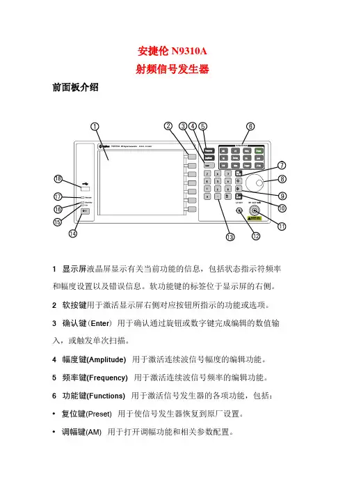
安捷伦N9310A射频信号发生器前面板介绍1 显示屏液晶屏显示有关当前功能的信息,包括状态指示符频率和幅度设置以及错误信息。
软功能键的标签位于显示屏的右侧。
2 软按键用于激活显示屏右侧对应按钮所指示的功能或选项。
3 确认键(Enter) 用于确认通过旋钮或数字键完成编辑的数值输入,或触发单次扫描。
4 幅度键(Amplitude) 用于激活连续波信号幅度的编辑功能。
5 频率键(Frequency) 用于激活连续波信号频率的编辑功能。
6 功能键(Functions) 用于激活信号发生器的各项功能,包括:• 复位键(Preset) 用于使信号发生器恢复到原厂设置。
• 调幅键(AM) 用于打开调幅功能和相关参数配置。
• 调频键(FM) 用于打开调频功能和相关参数配置。
• 调相键(FM) 用于打开调相功能和相关参数配置。
• 脉冲调制键(Pulse) 用于打开脉冲调制功能和相关参数配置。
• I/Q 调制键(I/Q) 用于打开I/Q 调制功能。
*选配• 扫描键(Sweep) 用于打开扫频、扫幅以及低频扫描的功能和其相关参数配置。
• 触发系统功能键(Utility) 用于编辑系统设置。
• 本地键(Local) 用于使信号发生器从远程状态返回到本地状态。
• 文件管理键(File) 用于保存、调用或删除仪器的配置文件。
• 低频输出键(LF Out) 用于打开低频输出功能和相关参数配置。
7 调制开关(MOD On/Off) 按键激活或关闭调制器( 调幅、调频、调相、脉冲或I/Q 调制)。
此键并不会单独打开某种调制;请首先打开所需调制功能( 例如按> 调幅开)。
显示屏上的调制开/ 关指示条用来指示当前调制器状态。
8 旋钮用来编辑数值或反显数位大小及编辑文件名和选择文件。
9 方向键用于移动数值中的反显数位或状态显示区的条目。
10 射频输出开关(RF On/Off) 按键来打开或关闭RF OUT 端口的射频信号输出。
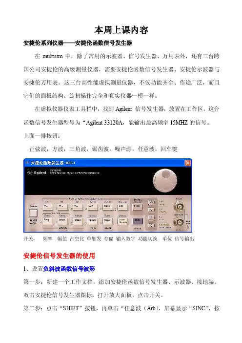
本周上课内容安捷伦系列仪器——安捷伦函数信号发生器在multisim中,除了常用的示波器、信号发生器、万用表外,还有三台跨国公司安捷伦的高级测量仪器,需要安捷伦函数信号发生器、安捷伦示波器与安捷伦万用表。
这三台高性能虚拟测量仪器,不仅功能齐全、作途广泛,而且它们的面板结构、旋扭操作完全和真实仪器一模一样。
在虚拟仪器仪表工具栏中,找到Agilent 信号发生器,放置在工作区。
这台函数信号发生器型号为“Agilent 33120A,能输出最高频率15MHZ的信号。
上面一排按钮:正弦波,方波,三角波,锯齿波,噪声源,任意波,回车键开关,频率幅值占空比单触发存储输入数字功能切换单位信号输出安捷伦信号发生器的使用1、设置负斜波函数信号波形第一步:新建一个工作文档,添加安捷伦函数信号发生器、示波器、接地端。
双击安捷伦信号发生器图标,打开放大面板,点击开关。
第二步:点击“SHIFT”按钮,再单击“任意波(Arb),屏幕显示“SINC”,按键盘上的“→”,屏幕显示“NEG_RAMP~”,单击“回车键”NEG表示负的,RAMP SIGNAL是斜波信号的意思。
第三步:点击“SHIFT”按钮,再两次单击“任意波(Arb)”按钮,屏幕显示“NEG_RAMP arb”第四步:设置波形的频率与幅度(Freq与Ampl)分别为2KHZ与2Vpp,观察波形。
2、设置指数函数信号波形第一步:新建一个工作文档,添加安捷伦函数信号发生器、安捷伦示波器、接地端。
双击安捷伦信号发生器图标,打开放大面板,点击开关。
第二步:点击“SHIFT”按钮,再单击“任意波(Arb),屏幕显示“SINC”,按键盘上的“→”键两次,屏幕显示“EXP_RISE~”,单击“回车键”EXP是函数的意思,FALL表示下降,RISE表示上升第三步:点击“SHIFT”按钮,再两次单击“任意波(Arb)”按钮,屏幕显示“EXP_RISE arb”,再按键盘上的“→”键,则屏幕显示“EXP_FALL arb”,最后,按“ENTER”进行保存。

Agilent-N9020A使用说明书功能测试XXXN9020A MXA操作手册1功能测试功能测试是对各种仪器参数的测试,这些参数对分析仪是否正常工作具有高度的信心。
建议在进货检验或修理后检查分析仪的运行情况。
测量不确定度分析不适用于功能测试,分析仪应根据比公布规范更宽的限值进行检查。
功能测试旨在使用最小的测试设备,测试分析仪在分析仪规范规定的温度范围内运行的分析仪。
如果测试未通过,则必须运行性能验证测试以确定是否存在问题。
功能测试与性能验证功能测试使用最少的测试设备来检查比性能验证测试小得多的参数范围(以及每个参数的有限数据点)。
功能测试使用比公布规范更宽的限值;测量不确定度分析不适用于功能测试。
注意如果功能测试未通过,则必须运行性能验证测试以确定是否存在问题。
性能验证测试涵盖了广泛的仪器参数,并提供了仪器符合公布规范的最高置信水平。
这些测试可能很耗时,需要大量的测试设备。
本文件内容本章包括以下内容:•“在举行功能测试之前”,(第一要做甚么)。
•“测试设备”(所有测试所需的设备清单)。
随后的章节描述了以下功能测试:•“显示平均噪声级(DANL)”•“频次读数精度”•“二次谐波失真(SHD)•“50 MHz振幅精度”•“50 MHz振幅精度”•“频次相应(平展度)”•“频次相应(平展度)前置放大器开启”•“刻度保真度”•“BBIQ输入频次相应(仅BBA选项),每个功能测试包括:•测试限值(合格/分歧格尺度)•测试说明•测试所需的设备•显示如何连接设备的图•逐步说明•记录测量结果的一个或多个表格在执行功能测试之前1.确保你有合适的测试装备。
2.打开被测单元(UUT)并使其预热(根据仪器规范中的预热要求)。
3.为所需的测试设备留出足够的预热时间(有关预热规范,请参阅单独的仪表文档)。
4.确保分析仪的频率参考设置为内部:a、按,键。
输入/输出更多频率参考输入b、如果软键不显示,请按软键并选择。
内部频率参考内部频率参考5.在仪器预热后,执行自动校准程序:按。
Agilent MXA Signal Analyzer N9020AData SheetThe MXA signal analyzer takes signal and spectrum analysis to the next generation, offering the highest performance in a midrange signal analyzer with the industry’s fastest signal and spectrum analysis,eliminating the compromise between speed and performance. With a broad set of applications and demodulationcapabilities, an intuitive user interface,outstanding connectivity and powerful one-button measurements, the MXA is ideal for both R&D and manufacturing engineers working on cellular,emerging wireless communications,general purpose, aerospace and defense applications.Available frequency ranges N9020A-503 20 Hz to 3.6 GHz N9020A-50820 Hz to 8.4 GHz N9020A-513 20 Hz to 13.6 GHz N9020A-52620 Hz to 26.5 GHzFully LXI class C compliant2Definitions and ConditionsSpecifications describe the performance of parameters covered by the product warranty and apply over 5 to 50 °C unless otherwise noted. 95th percentile values indicate the breadth of the population (≈2σ) of performance tolerances expected to be metin 95 percent of the cases witha 95 percent confidence, for any ambient temperature in the range of 20 to 30 °C. In addition to the statistical observations of a sample of instruments, these values include the effects ofthe uncertainties of external calibration references. These values are not warranted. These values are updated occasionally if a significant change in the statistically observed behaviorof production instruments is observed. Typical describes additional product performance information that is not covered by the product warranty.It is performance beyond specifications that 80 percentof the units exhibit with a95 percent confidence level over the temperature range 20 to30°C. Typical performance does not include measurement uncertainty. Nominal values indicate expected performance, or describe product performance that is useful in the application of the product, but is not covered by the product warranty.The analyzer will meet itsspecifications when:•The analyzer is within itscalibration cycle.•Under auto couple control,except that Auto Sweep TimeRules = Accy.•For signal frequencies<20MHz, DC coupling applied.•The analyzer has been storedat an ambient temperaturewithin the allowed operatingrange for at least two hoursbefore being turned on, if ithad previously been storedat a temperature range insidethe allowed storage rangebut outside the allowedoperating range.•The analyzer has been turnedon at least 30 minutes withAuto Align set to normal, orif Auto Align is set to off orpartial, alignments must havebeen run recently enough toprevent an Alert message. Ifthe Alert condition is changedfrom Time and Temperature toone of the disabled durationchoices, the analyzer may failto meet specifications withoutinforming the user.This MXA signal analyzer datasheet is a summary of thecomplete specifications andconditions, which are availablein the MXA Signal AnalyzerSpecification Guide. The MXASignal Analyzer SpecificationGuide can be obtained on the webat: /find/mxa.Then follow this selectionprocess:•Select Technical Support underKey Library Information•Select Manuals and Guides•Download specifications guide3Frequency and Time Specifications456Amplitude Accuracy and Range Specifications78Dynamic Range Specifications10Figure 1. Nominal dynamic range – Band 0, for second and third order distortion, 20 Hz to 3.6 GHz Figure 2. Nominal dynamic range – Bands 1 to 4, second and third order distortion, 3.6 GHz to 26.5 GHzSecond harmonic distortion (SHI)Mixer level Distortion SHI10 MHz to 1.8 GHz–15 dBm–60 dBc+45 dBm1.8 to 7.0 GHz–15 dBm–80 dBc+65 dBm7.0 to 11.0 GHz–15 dBm–70 dBc+55 dBm11.0 to 13.25 GHz–15 dBm–65 dBc+50 dBm Preamp on (Option P03, P08, P13, P26)Preamp level Distortion SHI10 MHz to 1.8 GHz–45 dBm–75 dBc nominal+30 dBm nominal1.8 to 13.25 GHz–50 dBm–60 dBc nominal+10 dBmThird-order intermodulation distortion (TOI) (two –30 dBm tones at input mixer with tone separation > 15 kHz, 20 to 30 °C )Distortion TOI Typical10 to 100 MHz –84 dBc+12 dBm +17 dBm100 to 400 MHz –88 dBc+14 dBm +18 dBm400 MHz to 1.7 GHz –90 dBc+15 dBm +19 dBm1.7 to 3.6 GHz –92 dBc+16 dBm+19 dBm3.6 to 8.4 GHz –90 dBc+15 dBm+18 dBm8.4 to 13.6 GHz –90 dBc+15 dBm+18 dBm13.6 to 26.5 GHz –80 dBc+10 dBm+14 dBm Preamp on (Option P03, P08, P13, P26)10 MHz to 3.6 GHz20 dB lower than non-preamp mode, nominal(two –45 dBm tones at preamp input) 3.6 to 26.5 GHz35 dB lower than non-preamp mode, nominal, for offset <10 MHz3.6 to 26.5 GHz–14 dB, nominal, for offset >20 MHzPhase noise3Noise sidebands Offset Specification Typical(20 to 30 °C, CF = 1 GHz)100 Hz –80 dBc/Hz –86 dBc/Hz1 kHz –100 dBc/Hz nominal10 kHz –103 dBc/Hz –106 dBc/Hz100 kHz –115 dBc/Hz –117 dBc/Hz1 MHz –134 dBc/Hz –136 dBc/Hz10 MHz –147 dBc/Hz nominal 3For nominal values, refer to Figure 3.Figure 3. Nominal phase noise at different center frequencies (with Option PFR)Power Suite Measurement SpecificationsPower Suite Measurement Specifications (continued)General SpecificationsGeneral Specifications (continued)Input and OutputsInput and Outputs (continued)MXA Signal Analyzer Ordering InformationFor further information, refer to MXA Signal Analyzer Configuration Guide (5989-4943EN)Related LiteratureAgilent Technologies’ Test and Measurement Support, Services, and AssistanceAgilent Technologies aims to maximize the value you receive, while minimizing your risk and problems. We strive to ensure that you get the test and measurement capabilities you paid for and obtain the support you need. Our extensive support resources and services can help you choose the right Agilent products for your applications and apply them successfully.Every instrument and system we sell has a global warranty. Two concepts underlie Agilent’s overall support policy: “Our Promise” and “Your Advantage.”Our PromiseOur Promise means your Agilent test and measurement equipment will meet its advertised performance and functionality. When you are choosing new equipment, we will help you with product information, including realistic performance specifications and practical recommendations from experienced test engineers. When you receive your new Agilent equipment, we can help verify that it works properly and help with initial product operation.Your AdvantageYour Advantage means that Agilent offers a wide range of additional expert test and measurement services, which you can purchase according to your unique technical and business needs. Solve problems efficiently and gain a competitive edge by contracting with us for calibration, extra-cost upgrades, out-of-warranty repairs, and on-site education and training, as well as design, system integration, project management, and other professional engineering services. Experienced Agilent engineers and technicians worldwide can help you maximize your productivity, optimize the return on investment of your Agilent instruments and systems, and obtain dependable measurement accuracy for the life of those products.For more information on Agilent Technologies’products, applications or services, please contact your local Agilent office. The complete list is available at:/find/contactus Phone or Fax United States:(tel) 800 829 4444(fax) 800 829 4433Canada:(tel) 877 894 4414(fax) 800 746 4866China:(tel) 800 810 0189(fax) 800 820 2816Europe:(tel) 31 20 547 2111Japan:(tel) (81) 426 56 7832(fax) (81) 426 56 7840Korea:(tel) (080) 769 0800(fax) (080) 769 0900Latin America:(tel) (305) 269 7500Taiwan:(tel) 0800 047 866(fax) 0800 286 331Other Asia Pacific Countries:(tel) (65) 6375 8100(fax) (65) 6755 0042Email:*****************Contacts revised: 05/27/05Product specifications and descriptions in thisdocument subject to change without notice.© Agilent Technologies, Inc. 2006Printed in USA, August 31, 20065989-4942EN Agilent Email Updates/find/emailupdates Get the latest information on the products and applications you /find/mxa/find/agilentdirectQuickly choose and use your test equipment solutions with confidence.Agilent Open /find/open Agilent Open simplifies the process of connecting and programming test systems to help engineers design, validate and manufacture electronic products. Agilent offers open connectivity for a broad range of system-ready instruments, open industry software,PC-standard I/O and global support, which are combined to more easily integrate test system development.。
Keysight N9038AMXE EMI Receiver–3 Hz up to 44 GHz frequency range–Compliant with CISPR 16-1-1:2010 and MIL-STD-461–± 0.5 dB at 1 GHz amplitude accuracySummary of Key SpecificationsThe X-Series difference Future-readyOptimize your investment and extend instrument longevity with upgradeable processor, memory, connectivity, and more to keep your test assets current today and tomorrow.Consistent measurement frameworkAchieve measurement integrity across your organization and drive more productivity in less time by leveraging a proven foundation for signal analysis and identical operation across the X-Series instruments.Broadest set of applicationsAddress the changing demands of technology with additionalmeasurement applications, the ability to run software inside the openWindows operating system, and a first-to-market track record in emerging standards.Stay ready, stay in sync, and arrive ahead —with the Keysight X-Series./find/X-SeriesKeep the Test Queue FlowingIn EMC testing, success depends on tools that can help you do more in less time—today and tomorrow. That’s why we created the MXE: it’s a standards-compliant EMI receiver and diagnostic signal analyzer built on an upgradeable platform. In the lab and on the bench, it provides the accuracy, repeatability,and reliability you need to test with confidence.The MXE makes it easy to test in accordance with CISPR 16-1-1:2010 and MIL-STD-461. Choose the frequency coverage you need—up to 3.6, 8.4, 26.5, or44 GHz—and fully test devices with outstanding accuracy and excellent sensitivity across the required ranges.Through the front panel or remotely with software, you can evaluate emissions and identify suspect signals using EMC measurements and a variety of intuitive displays. The extensive set of built-in analysis tools helps you diagnose the causes of noncompliant emissions.With all these capabilities and more, the MXE enables you and your team to keep the test queue flowing.Extend instrument longevity with easy upgradabilityTo keep your instrument current and extend its longevity, the MXE offers easy upgradability of hardware and software capabilities. For example, you can enhance platform performance through CPU and memory upgrades, and add functionality with a simple license key.Leverage the proven reliability of a mature hardware platform Uptime is essential in a test lab and that’s why we built the MXE on the robust Keysight X-Series signal analyzer platform. In addition, the MXE carries the benefits of Keysight’s standard three-year warranty and responsive service and support team.The MXE is ideally suited for high-performance EMC testing in commercial and military applications. The instrument offers a range of CISPR- and MIL-STD-compliant capabilities—detectors, bandwidths, and more—as well as features that further enhance the accuracy and throughput of EMC testing and data analysis.Simplify setupThe MXE contains a number of features that simplify the setup process for compliance measurements. For example, you can use setup tables to create specific measurement configurations for a variety of frequency ranges and antennas. You can also reduce overall setup time by saving and recallingfrequently used custom instrument settings. In addition, the MXE can remotely control switching functions in external LISNs.To accelerate identification of suspect emissions, access the built-in library of limit lines and activate the relevant regulatory limits. You can also define custom limit lines with the easy-to-use editor. To ensure appropriate limit testing, the MXE can automatically correct measured amplitudes for specific transducers, antennas, cabling, and external preamplifiers using customer-configured amplitude correction files.Accelerate data collectionThe MXE is designed to help you see signal activity—quickly and easily—from multiple perspectives. The comprehensive user display allows you to see both a broad overview of the emissions environment and a detailed view of the signal amplitude at a single frequency.Easily capture emissions data using built-in automated scan, search, and measure functions that mirror recommended commercial and military testing procedures. The multi-trace and max hold capabilities let you view emissions from the current position of the device under test (DUT) along with themaximum emissions from all DUT positions. During monitoring, the three color-coded detectors are updated simultaneously to ensure accurate results.The MXE receiver display provides a simplified view into the emissions performance of the DUT.Maximize Throughput in Compliance TestingChoose from traditional frequency or rapid time domain scanning.Easily identify suspect signalsWith built-in measurement and analysis functions, the MXE makes it easy to identify suspect emissions. For example, the unique color-coded trace display capability clearly identifies signals that exceed the selected limit lines and margins.When creating suspect lists, you can choose between traditional frequency scanning and rapid time domain scanning. Time domain scans significantly reduce the time needed to create a list of suspect emissions prior to making final measurements.Built-in limit testing makes it easy to create emission suspect lists. The receiver can automatically move out-of-limit signals to the signal list, where you can perform measurements with the touch of a button.Simplify final measurementsThe list function in the MXE makes it easy to perform final emissionsmeasurements for all supported standards. When you need to control tower or turntable position, internal frequency lists can be passed to automationsoftware. When orientation optimization isn’t required, built-in capabilities help you complete final measurements with ease.When final measurements are complete, you can conveniently create reports in HTML or PDF format with customized content that includes amplitude corrections, limits, scan tables, trace data, signal lists, and screen shots.All-digital IF architectureA digital intermediate frequency (IF) receiver architecture improvesmeasurement accuracy. By comparison, an analog IF architecture implements gain blocks, log amps, resolution bandwidths, and detectors with analog hardware. Even the best of these designs exhibit performance differences when receiver settings are changed from the settings used for calibration. These differences are then exacerbated over temperature.The all-digital IF architectureincludes digital realizations of the key components, which operate on the signal after it has been digitized. Digital IF can improve EMC measurement throughput by minimizing the need for users to bring the signal being measured to the top of the reference level. Analog receivers require this step for every measurement to minimize the effects of analog hardware errors.In addition, digital IF architecturereduces the occurrence of IF overload, even if signals are above the reference level.As an EMI receiver and diagnostic signal analyzer, the MXE puts a wealth of capabilities at yourfingertips. New receiver technology reduces measurement time and ensures you are prepared for future requirements.Go faster with time domain scanningThe MXE offers three types offrequency scanning: swept, stepped, and time domain. Time domain scan decreases total test time by reducing overall prescan collection times when longer measurement dwell times are required.Time domain scan speedsmeasurements by using high-overlap fast Fourier transforms (FFTs) tocollect emissions data simultaneously over an acquisition bandwidth that is multiple resolution bandwidths wide. This is in contrast to frequency-domain measurements, whichcollect data in individual resolution bandwidths.With time domain testing, you can collect suspect lists rapidly, greatly improving overall test time and throughput.Automate click measurementsUse the MXE's built-in disturbance analyzer to easily make discontinuous disturbance, or click, measurements as specified in CISPR 14-1. Simplify and automate data collection, analysis, and report generation for these commonly tested emissions for more efficient testing.Enhance Your Lab with the Latest CapabilitiesComparison of resolution and FFT acquisition bandwidths.FrequencyA m p l i t u d eFFT acquisition bandwidthA m p l i t u d eFrequencyReceiver resolution bandwidthSwept or stepped frequency domain scanTime domain scanDwell for each resolution bandwidthDwell for each FFT bandwidth (multiple resolution bandwidth)Simplify and automate data collection, analysis, and report generation for click measurements.Be ready for APD measurementsThe MXE helps future-proof your lab by offering the amplitude probability distribution (APD) function that is being considered by CISPR foremissions testing of microwave ovens. To characterize slowly-varyingemissions, the APD function displays the probability of an emissionreaching or exceeding a given level. To facilitate use of this new function, the MXE also offers specific limit-line types that can be used with built-in evaluation capabilities to simplify DUT testing.Find the maximum with monitor spectrumIn EMC testing, capturing the maximum value of each emissionfrequency is crucial. Doing so enables accurate characterization of the DUT.To ensure that you have identified the frequencies of maximum emissions in your suspect list, the MXE offers a new feature called monitor spectrum. This feature offers both live-spectrum and meter displays that make it easy to see emission levels and find the maximum while adjusting the center frequency. Ultimately, monitor spectrum improves overall measurement time by reducing the time it takes to prepare your signal list for final measurements.Monitor spectrum identifies frequency of peak emissions.Be ready for future applications with the APD function.The global center frequency feature lets you easily track signals in both the receiver and spectrum analyzer.Gain Insight with Extensive Diagnostic CapabilitiesVerifying product compliance is just one facet of EMI testing. Solving emissions problems can present a wide range of challenges, and the MXE offers a number of tools that will help you see and understand what’s happening.Leverage powerful spectrum analysisInvestigate out-of-compliance emissions with the MXE’s built-in X-Series spectrum analysis capabilities, which include a rich set of resolution and video analysis bandwidths, detectors, and marker functions. In addition, the MXE includes the X-Series PowerSuite measurements for characterization of transmitted signals.Switching between receiver and spectrum analyzer modes is greatlysimplified with the global center frequency function, which links the viewed frequencies. When analyzing an emission, any modification of its frequency will be automatically updated in the MXE’s suspect list, simplifying the final measurement process.Enhance precompliance measurementsYou can leverage the power and usability of the MXE when making precompliance measurements. The Keysight EMI measurement applications (N6141A and W6141A) put the functionality of the MXE inside any of our X-Series signalanalyzers: PXA, MXA, EXA, or CXA. The excellent sensitivity of the X-Series signal analyzers translates into highly accurate emissions measurements.For PXA, MXA or EXA:/find/N6141A For CXA:/find/W6141AStrip Chart mode provides a unique, gap-free view that is useful fortracking DUT performance as a function of turntable or antenna position.Spectrogram displays and the signal-marker capability help you understand the amplitude–and time-varying nature of emissions.RTSA lets you see and understand high-speed transient signals that aredifficult to capture.See amplitude variation vs time with Strip ChartCharacterize the variation of signal amplitude versus time using Strip Chart, a Keysight-exclusive feature which plots data for up to three detectors. All collected data isgapless, with a two-hour time record. This feature is especially useful for capturing the azimuthal emissions characteristics of a DUT when testing on a turntable.The frequency used for the Strip Chart display is coupled to the suspect list, making it easy to view each signal in the suspect list.View varying emissions with spectrograph displaysObserve how emissions spanning a broad spectral range change over time using the built-in spectrograph display. Tracking any variations in spectral data can provide clues about the origins of out-of-compliance emissions.Capture transient signals with real-time spectrum analysisDiagnose high-speed transient signals using real-time spectrum analysis (RTSA) with frequencymask trigger capability. Preselected microwave RTSA enables image-free, over-the-air signal analysis so you can more quickly and easily analyze sources of radiated emissions.Build a Complete EMI Test SolutionProtect Your Investment with an Upgradable PlatformOur qualified Keysight Solution Partners provide a single point of contact to purchase complete EMI measurement solutions that meet commercial and military specifications. In addition to the MXE EMI receiver, they can provide equipment including chambers, probes, towers and antennas, and services such as integration, installation, training, and support. To further simplify testing, they also offer automation software that can meet your specific needs.If you need to go beyond emission and immunity, our solution partners can provide ESD, line harmonics, droop testing, and more.To keep your instrument current and extend its longevity, the MXE offers easy upgradability of hardware and software. When needed, you can enhanceplatform performance through upgradable CPU, memory, disk drives, and I/O ports. Internally, the mechanical assembly has three expansion slots that can accommodate future enhancements.On the software side, simple license-key upgrades are all it takes to add functionality or measurement applications. For example, the external source control option lets the MXE interface with a variety of Keysight signalgenerators, enabling stimulus/response testing up to 20 GHz. For detailed signal analysis, the library of available measurement applications includes analog demodulation, phase noise, and noise figure.Upgrade frequencyThrough return-to-Keysight upgrades, you can extend the frequency range of MXE EMI receivers up to 44 GHz. The receiver maintains its options, applications, and serial number.While the receiver is at the service center for a frequency extension, it is a convenient time to add functionality such as time domain scan for fast FFT-based frequency scanning.For precompliance testing, Keysight also offers frequency upgrades on PXA, MXA, or EXA signal /find/frequencyup11 | Keysight | MXE EMI Receiver N9038A - BrochureMXE Front and Rear PanelsView up to threedifferent prehensive display provides view of spectrum, meters, and suspect list.Second inputpulse-protected to 2 kW.Removable CPU enables processor, memory, and I/O upgrades.Auxiliary/IO port for LISN control.Send and receive SCPI commands over the GPIB interface.Identify signals and view information easily on the 21.4-cm, high-resolution XGA display.Acquire IQ waveform data quickly or control the MXE remotely from an external PC over the USB 2.0 (type-B port) interface.Synchronize other test equipment with the analyzer using the external trigger output signals.Get answers quickly with the comprehensive, context-sensitive embedded help system.Connect external peripherals and transfer data via the USB 2.0 (type-A port) interface.Navigate the interface and help system using the front-panel keys, or a mouse and keyboard.Test devices up to 44 GHz.View the display on an external monitor by connecting to the VGA video output.Two USB 2.0 ports conveniently located on the front of the instrument.Control the MXE remotely over1000Base-T LAN.Removable solid-state drive.Additional solid-state driveavailable for instrument security.Save files fast with the quick-save feature.12 | Keysight | MXE EMI Receiver N9038A - BrochureThis information is subject to change without notice.© Keysight Technologies, 2013 - 2018Published in USA, March 27, 20185990-7422ENRelated LiteratureKeysight MXE EMI receiverPublication title Publication number Data Sheet5990-7421EN Configuration Guide5990-7419EN X-Series Measurement Application Brochure5989-8019EN/find/mxeEvolving Since 1939Our unique combination of hardware, software, services, and people can help you reach your next breakthrough. We are unlocking the future of technology.From Hewlett-Packard to Agilent to Keysight.myKeysight/find/mykeysightA personalized view into the information most relevant to you. /find/emt_product_registrationRegister your products to get up-to-date product information and find warranty information.Keysight Services/find/serviceKeysight Services can help from acquisition to renewal across your instrument’s lifecycle. Our comprehensive service offerings—one-stop calibration, repair, asset management, technology refresh, consulting, training and more—helps you improve product qualityand lower costs.Keysight Assurance Plans/find/AssurancePlansUp to ten years of protection and no budgetary surprises to ensure your instruments are operating to specification, so you can rely on accurate measurements.Keysight Channel Partners/find/channelpartnersGet the best of both worlds: Keysight’s measurement expertise and product breadth, combined with channel partner convenience.For more information on KeysightTechnologies’ products, applications or services, please contact your local Keysight office. The complete list is available at:/find/contactus Americas Canada (877) 894 4414Brazil 55 11 3351 7010Mexico001 800 254 2440United States (800) 829 4444Asia Pacific Australia 1 800 629 485China800 810 0189Hong Kong 800 938 693India 1 800 11 2626Japan 0120 (421) 345Korea 080 769 0800Malaysia 1 800 888 848Singapore 180****8100Taiwan0800 047 866Other AP Countries (65) 6375 8100Europe & Middle East Austria 0800 001122Belgium 0800 58580Finland 0800 523252France 0805 980333Germany ***********Ireland 1800 832700Israel 1 809 343051Italy800 599100Luxembourg +32 800 58580Netherlands 0800 0233200Russia 8800 5009286Spain 800 000154Sweden 0200 882255Switzerland0800 805353Opt. 1 (DE)Opt. 2 (FR)Opt. 3 (IT)United Kingdom0800 0260637For other unlisted countries:/find/contactus(BP-9-7-17)/go/quality Keysight Technologies, Inc.DEKRA Certified ISO 9001:2015Quality Management System。
Agilent U8903A Audio AnalyzerMake an Audible DifferenceData SheetCapabilities• Select generator, analyzer, graph, and sweep modes with one-button access • Measure at DC and from 10 Hz to 100 kHz • Characterize signal-to-noise ratio, SINAD, IMD, DFD, THD+N ratio, THD+N level, crosstalk, and more • Apply weighting functions, standard filters, and custom filters • Stimulate the device with high-quality signals and arbitrary waveforms • View numerical and graphical displays of measurement results • Connect to a PC through GPIB, LAN/LXI C, and USB interfaces • Code compatible with HP8903B • 2 in 1 screen (generator and analyzer in the same display screen)Whether listening to mono, stereo, or surround, the human ear knows what sounds good. Measuring “how good,” however, can be a challenge. The Agilent U8903A audio analyzer helps you measure and quantify audio performance in applications such as wireless audio, analog components and ICs, and consumer audio.Across the audio spectrum and beyond, this scalable, single-unit solution provides versatile measurement functions, diverse test signals, and powerful analysis capabilities.The U8903A audio analyzer combines the functionality of a distortion meter, SINAD meter, frequency counter, AC voltmeter, DC voltmeter, and FFT analyzer with a low-distortion audio source. On the bench or in a test system, its accu-racy and versatility helps you make an audible difference in your end product.LXI class C certified1981Table 1. Comparison of frequency range and accuracyFrequency range DC and 10 Hz to 100 kHz20 Hz to 100 kHz Frequency accuracy 5 ppm (0.0005%)0.004%Table 2. Comparison of accuracy and ranges in AC and DC level measurementsAC voltage input range0 V to 140 Vrms 0.3 mVrmsto 300 VrmsAC accuracy± 1%± 4%DC voltage input range0 to ± 200 V 4 to 300 VDC accuracy± 1%± 1%Table 3. Comparison of range and residual THD+N measurements Frequency range10 Hz to 100 kHz20 Hz to 100 kHzResidual THD+N (signal distortion) at 80 kHz BW ≤ –101 dB (at 1 kHz, 1 Vrms),20 Hz to 20 kHz–80 dB (or 15 µV),20 Hz to 20 kHzAccuracy± 0.5 dB (< 20 kHz)± 0.7 dB (< 100 kHz)± 1 dB (20 Hz to 20 kHz)± 2 dB (20 to 100 kHz)Figure 1. The new U8903A audio analyzer (left) offers numerous improvements over the widely used HP 8903B (right). Replace your 8903B and addnext-generation capabilitiesFor nearly two decades, the HP 8903Bprovided unparalleled versatility andperformance in audio applications.The U8903A builds on the legacy ofthe 8903B by offering faster single-point measurements (0.4 sec versus3.0 sec) as well as a wider frequencyrange, expanded performance, andgreater functionality (Tables 1, 2, and3). With the U8903A, you can con-figure measurements faster throughits graphical user interface (GUI)and one-button selection of majoroperating modes. The color screenlets you view dual-parameter displaysfrom one or two channels as wellas graphical displays of sweeps, fre-quency spectra, and more (Figure 1).To makes the transition easy, thenext-generation replacement for theHP 8903B audio analyzer featuresa built-in code emulator whichautomatically converts 8903B R2D2code directly into SCPI commandsused by the U8903A. The Agilentapplication note Migrating Code fromthe 8903B to U8903A (5990-4135EN)and the U8903A Programming Guide(U8903-90027) provide additionalresources to assure you get the mostfrom this new class of audio analyzer.23Measure and analyze essential audio parametersWith the U8903A, you can measure below, across, and above the audio spectrum with its 10 Hz to 100 kHz frequency range and built-in DC mea-surements. Its dual input channels let you perform stereo audio, frequency response, wireless and component tests—all at a single-channel price.Easily characterize parameters such as signal-to-noise ratio, SINAD, intermodulation distortion (IMD), different-frequency distortion (DFD), total harmonic distortion (THD+N ratio, THD+N level), crosstalk, and more. Additional measurementcapabilities include AC level, DC level, frequency count, frequency spectrum, and FFT analysis (Figure 2).For all measurements, you canapply weighting functions as well aslow-pass, high-pass, and standardFigure 2. Perform FFT analysis with up to 32 Kpoints and a wide selection ofinformative graphing functions Figure 3. Apply an extensive selection of filters, including a variety of weightingfunctionsFigure 4. Utilize high-quality test signals that provide low distortion and low noise levelFigure 5. 2 in 1 screen generator and analyzer in the same display screenAddress Challenging Audio Applicationsfilters (Figure 3). You can also create custom filters using MATLAB ® and other applications, and upload them through the analyzer’s USB port.Filters and weighting functions can be applied one, two, or three at a time.U8903A also provides a 2 in 1 screen, which simultaneously displays the generator and analyzer information (Figure 5). This allows the user to change the generator (source) setting while monitoring the analyzer results in real time.Generate high-quality test signalsThe built-in, dual-channel signal gen-erator lets you stimulate your device with a variety of high-quality signals: sine (–105 dB noise floor), square, rectangular, noise (Gaussian andrectangular), two-tone, and multi-tone (up to 60) (Figure 4). To simulate com-plex and real-world signals, you can also create arbitrary waveforms with up to 16,384 points and at 312.5 kHz sampling rate.The output voltage range is 0 V to 8 V rms with 1% accuracy. For unbal-anced connections, you can select 50 or 600 Ω output impedance.Easily perform manual and automated testsOne-button access makes it easy to select the four main operating modes: analyzer, generator, graph, and sweep. The 5.7-inch color display provides numeric readouts as well as graphical views of analog sweeps, FFT spectra, and more.For PC-based control on the bench or in a test system, the U8903A includes GPIB, LAN/LXI C, and USB interfaces.4Take a Closer LookFront panelPlug-and-play USB 2.0 connectivityFront-panel output on/off button for DUT protectionQuick buttons for graphical analysisOne-button access to analyzer, generator, and sweep modes5.7-inch color displaySoftkeys for easy function selectionDual-channel generator outputs and analyzer inputs with XLR connectorsFigure 6. U8903A audio analyzer, front viewRear panelGPIB, LAN/LXI C, and USB interfacesFigure 7. U8903A audio analyzer, rear view5Advance Measurement TestingGeneral audio testingThe U8903A provides essentialmeasurement capabilities that enable efficient analysis of audio amplifiers and other devices in the audio chain. For example, the analyzer includes balanced and unbalanced outputs and inputs. It also provides a wide selection of filters and enhances your flexibility by making it easy to upload customized filters. With an array of sweep functions and flexible data display formats for each measure-ment, you’ll be ready to address a wide range of challenging audio applications.Balanced inputsIn the quest for higher output power, many audio amplifiers use bridged output stages. Such amplifiers can be difficult to characterize because their outputs cannot be grounded. To test these devices, the usual approach has been to use a balanced, calibrat-ed isolation transformer connected to an analyzer with an unbalanced input.The widely used HP 8903B eliminated the need for a transformer, but it was still necessary to float the analyzer input before connecting the bridged device and making measurements. With the U8903A, you simply make a balanced connection with an XLR connector and make measure-ments—no floating required.Standard and custom filtersA selection of built-in filters simplifies audio measurements by providing weighting networks required by inter-national standards. These include CCIR, CCIR/ARM, and CCIT weighting filters; a C message filter; and an ANSI “A” weighting filter. In addition to the standard filters, you can create custom filters using applications such as MATLAB or Agilent VEEand upload the filters through theAmplifier testingGenerator outputAudio amplifierAnalyzer inputFigure 8. Audio testing using the U8903AFigure 9. Use a single button to access the swept measurement modeanalyzer’s USB port. The U8903A also includes selectable 15, 20, and 30 kHz low-pass filters to reject unwanted, out-of-band signals and noise.Display scaling and formatting U8903A gives you flexible control over data displays. For example, you can choose volts, millivolts, dBm into 600 Ω (or other resistance values), or watts for AC level measurements, and select percent or dB for distortion measurements.Swept measurementsWith its internal audio source and precise digital control, the U8903A can perform automatic swept mea-surements of frequency response, distortion, and signal-to-noise. For example, to check the frequencyresponse of an active filter, only a few steps are required. After connecting the device and setting the required source level, simply enter the start and stop frequencies, and then press the “Sweep” key (Figure 9).6Transmitter and receiver testingThe U8903A includes severalmeasurement features that simplify the testing of the transceivers used in devices such as car radios,telephones, mobile radios, broadcast radios, FM tuners, and television. The U8903A can handle all of these applications when combined with a modulating signal generator for receiver testing and a signal analyzer for transmitter testing (see diagrams on next page).True-RMS detectionTo accurately characterize signals with high noise content, true-RMS detection is required. The U8903A employs true-RMS detection for all signals with crest factor less than three. In addition, quasi-peak detec-tion (CCIR 468-4) and peak-to-peak detection are also available through softkey selections.Built-in filtersThe U8903A includes a variety of essential filters for transmitter and receiver testing. Its CCITT, CCIR, and C-message weighting filters meet international standards for receiver testing. For transmitter testing, the seven-pole 400 Hz high-pass filter provides better than 40 dB rejection of signals up to 250 Hz, letting you measure transmitter audiodistortion to 1% without disabling squelch signals.For even greater flexibility, you can apply custom filters created using applications such as MATLAB and Agilent VEE. Once you’ve uploaded a filter via the U8903A’s USB port, it can be applied to your measurements through a softkey selection. In all, you can apply up to three filters at a time.SINAD and THD+N measurementU8903A gives you the flexibility to lock down the generator frequency under the Frequency Lock features. With this feature, users can set the generator frequency in order to tell the location of the fundamental signal. In this case, users have the flexibility to lock the external source’s fundamental frequency to make SINAD and THD+N measurements more accurately because the mea-surements are based on the actual source fundamental signal rather than the detected fundamental signal. Sometimes the other order signal and noise is stronger than the actual source fundamental signal which will impact the measurement reading.Reference/relative measurements This features allows users to perform measurement on level, frequency, and ratio based on the selected impedance value, frequency, or ratio reference value. This simplifies manual data measurement and data collection because the calculations are automatically generated inside the equipment in real time. This fea-ture provides users with the flexibility to decided which signal sources to perform Signal-to-Noise (SNR) mea-surement without solely depending on the U8903A generator source. SINAD measurementsCommonly used to test FM receivers, SINAD measurements must be made repeatedly when checking receiver sensitivity or adjacent-channel selectivity. To smooth out the typi-cally noisy signals that are present during receiver testing, the analyzer’s SINAD mode employs extra filtering circuits. These are optimized for high speed and excellent repeatability: the U8903A provides distortion and SINAD measurements with an acqui-sition time of less than 1.5 seconds and a measurement rate of greater than two reading per second after locking.Signal-to-noise ratioTo characterize signal quality in AM receivers, the U8903A can automatically make the necessary signal-to-noise ratio measurements. It does this by monitoring the incoming AC signal level while turning its low-distortion source on and off.The U8903A provides the average point features which allows users to set the number of readings used for averaging. The display value will be the averaged value based on the number of points selected. This allows users to analyze noisy signals using an increased number of average points for greater accuracy.7Figure 10. Receiver testing using the U8903AGenerator outputModulated signalAnalyzer inputTwo-way Signal generatorReceiver testingTransmitter testingFigure 11. Transmitter testing using the U8903A and a spectrum analyzerGenerator outputModulated signalSpectrum analyzerTransmitter and receiver testing8CharacteristicsPower consumption 250 VA Power requirements • 100 to 240 V ac • 47 to 63 Hz Operating environment• Operating temperature from 0 to 55 °C• Relative humidity at 20 to 80% RH (noncondensing)• Altitude up to 3000 m • Pollution degree 2•Installation category IIStorage compliance –55 to 75 °C (23 to 167 °F)Safety complianceCertified with:• IEC 61010-1:2001/EN61010-1:2001 (2nd Edition)• Canada: CAN/CSA-C22.2 No. 61010-1-04• USA: ANSI/UL 61010-1:2004EMC compliance• IEC 61326-1:2005/EN 61326-1:2006• Canada: ICES-001:2004• Australia/New Zealand: AS/NZS CISPR11:2004Dimensions (W x D x H)425.6 mm x 405.0 mm x 133.6 mm (16.76 inches x 15.94 inches x 5.25 inches)Weight < 8.5 kg (< 18.74 lb) (without cards)Warranty• One year for U8903A• Three months for standard-shipped accessories (see page 13)SpecificationsThe following specifications are based on performance with 30 minutes of warm-up time and a temperature from 0 to 55 °C, unless stated otherwise.Generated waveformSine, dual sine, variable phase, square, noise (Gaussian and rectangular), arbitrary, DC, multitone, SMPTE IMD (1:1, 4:1, and 10:1), DFD (IEC 60118/IEC 60268)Sine, dual sine, and variable phaseFrequency Range Accuracy Resolution5 Hz to 80 kHz 5 ppm 0.1 HzOutputRange (balanced) Range (unbalanced/common) Amplitude accuracy Amplitude resolution 0 V to 16 V rms 0 V to 8 V rms ± 1%1 μV rms (limited to five digits of resolution)Flatness20 Hz to 20 kHz 5 Hz to 80 kHz ± 0.01 dB ± 0.1 dBTHD + N at 1 kHz, 1 V rms , 20 Hz to 20 kHz bandwidth ≤ –95 dB (at 23 °C ± 5°C)≤ –92 dB (from 0 to 55 °C)Dual sine ratio range 0 to 100 dB Phase –180 ° to 179.99 °SweepFrequency, amplitude, phaseOutput levelRangeAmplitude accuracy –11.3 to 11.3 V ± 1.5%9Output characteristic Connection typeBalancedUnbalancedCommon mode XLR BNC XLRImpedanceBalanced Unbalanced 100, 600 Ω50, 600 ΩOutput current limit (typical)50 mA Maximum output power into 600 ΩBalanced (600 Ω) Unbalanced (600 Ω)20 dBm 14 dBmCrosstalk20 Hz to 20 kHz 20 to 80 kHz ≤ –101 dB (at 23 °C ± 5 °C)≤ –99 dB (from 0 °C to 55 °C)≤ –85 dBInput characteristics Connection typeBalanced Unbalanced XLR BNCCoupling DC, AC Measurement bandwidthLow High 30 kHz 100 kHzInput ranges400 mV to 140 VrmsMeasurement range< 1 μV1 to 140 VrmsMaximum rated input200 Vp for altitude up to 3,000 m (1.86 miles) ImpedanceBalanced Unbalanced 200 kΩ100 kΩFlatness20 Hz to 20 kHz 20 to 100 kHz ± 0.01 dB2 (at 23 °C ± 5 °C)± 0.012 dB3 (from 0 °C to 55 °C)± 0.1 dB (at 23 °C ± 5 °C)± 0.15 dB (from 0 °C to 55 °C)CMRR≤ 20 kHz (input range ≤ 6.4 V)≤ 20 kHz (input range > 6.4 V)≥ 70 dB4≥ 40 dB4Crosstalk20 Hz to 20 kHz≤ –101 dBInput protection Overload protection for all ranges, onscreen warning message on the front panel1. Defined by 24-bit measurement.2. ± 0.01 dB – 0.001 dB/Hz below 50 Hz.3. ± 0.012 dB – 0.001 dB/Hz below 50 Hz.4. When AC coupled, CMRR will deteriorate at low frequencies.10Range10 Hz to 100 kHz Minimum input 1 mV (S/N > 40 dB) Accuracy 5 ppm Resolution 6 digitsGraph modeSize/acquisition length256, 512, 1024, 2048, 4096, 8192, 16384, 32768Window Rectangular, Hann, Hamming, Blackman-Harris, Rife-Vincent 1 and 3, Flattop Amplitude accuracy (flattop window)± 0.1 dB (± 1.2%)Display modeTime domainFrequency domain Normal, interpolate, peak, absolute value Displays highest FFT bin between graph pointsAudio filtersLow pass filter• 15 kHz low pass• 20 kHz low pass• 30 kHz low pass• User-defined1High pass filter• 20 Hz high pass• 100 Hz high pass• 400 Hz high pass• User-defined1Weighting filter• A-weighting (ANSI-IEC “A” weighted, per IEC Rec 179)• CCIR 1K weighted (CCIR Rec. 468)• CCIR 2K weighted (Dolby 2K)• C-Message (C-Message per IEEE 743)• CCITT (ITU-T Rec. O.41, ITU-T Rec. P.53)• User-defined11. User-defined filters can be uploaded through standard I/O connections.Figure 12. “A”weighting filter frequency responseFigure 13. CCIR-2K weighting filterFigure 14. CCIR-1K filter and CCIR-2K filter frequency responseFigure 15. CCITT filter frequency response“A” weighting filter frequency responseR e s p o n s e (d B )Frequency (Hz)“A” Weighting Filter (ANSI-IEC “A” weighted, per IEC Rec. 179)Deviation from ideal response:±0.1 dB at 1 kHz±0.5 dB, 20 Hz to 10 kHz ±1.0 dB, at 10 to 20 kHzR e s p o n s e (d B )Frequency (Hz)CCIR-2K weighting filter (Dolby 2K)Deviation from ideal response: same as listed previously under CCIR-1K weighting filterC-Message weighting filter (C-Message per IEEE 743)Deviation from ideal response:±0.1 dB, at 1 kHz±1.0 dB, 60 Hz to 5 kHz R e s p o n s e (d B )R e s p o n s e (d B )CCIR-1K filter and CCIR-2K filter frequency response CCITT filter frequency responseFrequency (Hz)Frequency (Hz)CCIR-1K weighting filter (CCIR Rec. 468)Deviation from ideal response:±0.1 dB, at 6.3 kHz±0.2 dB, at 6.3 to 7.1 kHz ±0.4 dB, at 7.1 to 10 kHz ±0.5 dB, at 200 Hz to 6.3 kHz±1.0 dB, at 31.5 to 200 kHz, 10 to 20 kHz±2.0 dB, at 20 to 31.5 kHzCCITT message weighting filter (ITU-T Rec. 0.41, ITU-T Rec. P.53)Deviation from ideal response:±0.2 dB, at 800 Hz±1.0 dB, at 300 Hz to 3 kHz ±2.0 dB, at 50 Hz to 3.5 kHz ±3.0 dB, at 3.5 to 5 kHzStop point–180 ° to 179.99 °1. This range is applicable for sine wave only.Ordering InformationU8903-1A7ISO17025 Compliant Calibration Test Data U8903A-A6J ANSI Z540 Compliant Calibration Test Data R-50C-011-3Agilent Calibration - 3 yearsR-50C-011-5Agilent Calibration - 5 yearsR-51B-001-3C Return to Agilent Warranty - 3 yearsR-51B-001-5C Return to Agilent Warranty - 5 years/find/audioanalyzerAgilent Email Updates/find/emailupdatesGet the latest information on theproducts and applications you select. LAN eXtensions for Instruments puts the power of Ethernet and the Web inside your test systems. Agilentis a founding member of the LXI consortium.Agilent Channel Partnersw w /find/channelpartners Get the best of both worlds: Agilent’s measurement expertise and product breadth, combined with channel partner convenience.Agilent Advantage Services is com-mitted to your success throughoutyour equipment’s lifetime. We sharemeasurement and service expertiseto help you create the products thatchange our world. To keep you com-petitive, we continually invest in toolsand processes that speed up calibra-tion and repair, reduce your cost ofownership, and move us ahead ofyour development curve./quality/find/advantageservicesFor more information on AgilentTechnologies’ products, applications orservices, please contact your local Agilentoffice. The complete list is available at:/find/contactusAmericasCanada (877) 894 4414Brazil (11) 4197 3500Mexico 01800 5064 800United States (800) 829 4444Asia PacificAustralia 1 800 629 485China 800 810 0189Hong Kong 800 938 693India 1 800 112 929Japan 0120 (421) 345Korea 080 769 0800Malaysia 1 800 888 848Singapore 180****8100Taiwan 0800 047 866Other AP Countries (65) 375 8100Europe & Middle EastBelgium 32 (0) 2 404 93 40Denmark 45 70 13 15 15Finland 358 (0) 10 855 2100France 0825 010 700**0.125€/minuteGermany 49 (0) 7031 464 6333Ireland 1890 924 204Israel 972-3-9288-504/544Italy 39 02 92 60 8484Netherlands 31 (0) 20 547 2111Spain 34 (91) 631 3300Sweden 0200-88 22 55United Kingdom 44 (0) 118 9276201For other unlisted Countries:/find/contactusRevised: October 14, 2010Product specifications and descriptionsin this document subject to changewithout notice.© Agilent Technologies, Inc. 2010, 2011Printed in USA, February 16, 20115990-3831ENMATLAB is a U.S. registered trademark of The Math Works, Inc.。
是德科技灵活的数字调制解决方案应用指南引言使用Keysight 33522B 双通道波形发生器和N9310A 射频信号发生器随着技术的快速发展,GFSK 等简单的数字调制信号在智能电网、近场通信(NFC)和许多电子消费产品中得到了广泛应用。
在研发或生产过程中,通常需要产生适合的数字调制信号来测试射频接收机的性能指标是否合格。
正如本应用指南的介绍,Keysight 33522B 双通道波形发生器和N9310A 射频信号发生器提供了一个低成本的解决方案,可以替代价格昂贵的矢量信号发生器。
本文将以GFSK 信号的生成为例,展示该解决方案卓尔不凡的简易性和灵活性。
生成GFSK 信号的准备本部分概括介绍了使用此低成本解决方案生成GFSK 信号所必需的软件和设备。
‾波形编辑软件用于编辑Keysight 33522B 波形发生器所使用的基带波形,以及设置33522B 的参数,如采样率和输出电平。
GFSK IQ Baseband Builder软件可从是德科技网站免费下载。
它是在MATLAB 8.0.0.783 版本(R2012b) 平台上开发完成,能够支持用户创建GFSK 基带波形。
它包含两个文件,您可以在MATLAB 环境中使用这两个文件:‾GFSK_N9310A_33522B_IQ.m―主要用于生成基带波形数据并将其下载到33522B 波形发生器。
‾Data.m―用于定制I/Q 基带信号‾一台Keysight 33522B 波形发生器这是一款 30 MHz 双通道波形发生器,采用独家的 Trueform 信号生成技术。
一旦波形数据从 GFSK IQBaseband Builder 发送到 33522B,33522B 就会根据这些数据生成适用于射频信号发生器的 I/Q 信号。
33522B 包含16 M 存储器和I/Q 基带信号播放器(选件MEM 和选件IQP)。
‾一台Keysight N9310A 射频信号发生器这是一款标配9 kHz 至3 GHz 频率范围以及模拟调制的通用射频信号发生器,其中还包含20 MHz 带宽I/Q 调制器(选件001),因此能够利用外部I/Q 基带信号生成数字调制信号。