SMC电磁阀VT307K-BDO1-01F外形尺寸
- 格式:doc
- 大小:474.31 KB
- 文档页数:2

EVT307-5DZ-01F-QLarge Flow Capacity, yet Compact Size. Dimensions (W X H X D)······30 X 54.5 X 33 VT307······N l/min 206.02 or more, 1/4 Low Power ConsumptionVT/VO307······4.8W DC/Standard StyleVT/VO307YVT/VO307W)······2W DC/Energy Saving Style Suitable for Use in Vacuum Applications –101.2kPa(Vacuum Style: VT/VO307V, VT/VO307W)1 Valve, 6 Functions. (Universal Porting)Selective porting can provide 6 valve func-tions, such as N.C. valve, N.O. valve, Divider valve, Selector valve etc.JIS Symbol 3 Port Direct Operated Poppet Rubber Seal Series VT3072.5-12.5-2Option SpecificationsHow to OrderExclusive use of VT307E is recommended for continuous duty with long time loading.VT307Caution1. This model is for continuous duty, not for high cycle rates. But even in low cycle rate, if energiz-ing valve more than once a day, consult SMC.2. Energizing solenoid shouldbe done at least once in 30 days.If low power consumption is required for electronic control, “VY307Y”(2WDC) is recommended.Specifications different from standard are as fol-This vacuum model has less air leakage than the standard model under low pres-sure.CautionSince this valve has slight air leakage, it can not be used for vacuum holding (including positive pressure holding) in the pressure container.Specifications different from standard are as follows.Operating pressure range–101.2kPa to 0.1MPa2.5-3Be sure to read before handling.Refer to p.0-33 to 0-36 for Safety Instruction and common precautions.1. Make sure that dust and/or other foreign materials should not enter the valve from the unused port such as exhaust port. Also, since there is a bleed port for the armature in the manual override part, do not allow accumulation of dust and/or other foreign materials to block bleed port.How to Calculate Flow RateRefer to p.0-36 for the calculation of flow rate.De-energizedEnergizedOperation principles <De-energized>Spool valve w is pushed upward by the return spring e , port [P] is closed, and then port [A] and port [R] are opened.Air flow direction:Port [P] Block, [A] [R]<Energized>When an electric current is applied to the molded coil r , the armature t is attracted to the pole y , and through the push rod u , it pushes down the spool valve w . Then port [P] and port [A] are con-nected. At this time, there will be gaps between the armature t and the pole y , but the armature will be magnetically attracted to the pole y . Air flow direction:VT307DIN connector (with indicator light and surge voltage suppressor) are connected inside as in the figure below. Connect to the cor-responding power supply.terminal blockblock • Applicable cable O.D. Type T: ø4.5 to ø7mm Type E: ø2.3 to ø2.8mm Type D: ø4.5 to ø7mm • Applicable crimp terminal T ype E/T: 1.25-3, 1.25-3S 1.25Y -3N, 1.25Y -3SRound or “Y” shaped crimped terminals Voltage 100V AC 200V AC DC OthersColour Blue RedRed (+), Black (–)GrayTerminal No.DIN Terminal Terminal1++ CautionoverrideVT3072.5-42.5-5VV307VT307 manifoldE Series VT307ManifoldCautionq Each valve is fixed to the manifold base with two M4 mounting screws. Tighten the screws evenly when re-mounting. w For mounting, tighten M4 or equivalent screws evenly into the mounting holes of the manifold base.Tightening torque of the mounting screw (M4): 1.4NmBe sure to read before handling.Refer to p.0-33 to 0-36 for Safety Instruction and common precautions.VT307 manifold is B mount style and available both as a common exhaust and individual exhaust model.Manifolded valve can be easily con-verted from N.C. normally closed to N.O. normally open merely by turn-ing over the switch cover.q For the common exhaust style, pressur-iza- tion or evacuation of the R-port can cause malfunction.VV307-01-052-FVV307-01-063- -FHow to Order Manifold BaseFigure: N.C.Note 1) "DXT060-51-13B" and "DXT152-14-1B" are for long time loading.Note 2) For mounting single solenoid valve for manifolds.Function PipingMounting2.5-6VT307VV307-01- 2-01-Fn: Station L: Dimensions (mm)VT307 L:Dimensions (mm)n: Station2.5-7Large Flow Capacity, yet Compact Size. Dimensions(W X H X D)······45 X 89.5 X 45 VT317······N l/min 687.05 1/4Suitable for Use in Vacuum Applications -101.2kPa(Vacuum Model: VT/VO317V)1 Valve, 6 Functions. (Universal Porting)Selective porting can provide 6 valve func-tions, such as N.C. valve, N.O. valve, Divider valve, Selector valve etc.JIS Symbol 3 Port Direct Operated Poppet Rubber Seal Series VT3172.5-82.5-9Option SpecificationsHow to orderExclusive use of VT317E is recommendedfor continuous duty with long time loading.VT3171. This model is for continuous duty, not for high cycle rates. But even in low cycle rates, if energizing the valve more than once a day, consult SMC.2. Energizing solenoid should be done at least once in 30 days.This vacuum model has less air leakage than the standard model under low pressure. It is recommended for vacuum applications.1. Since this valve has slight air leakage, it can not be used for vacuum holding (including positive pressure holding) in the pressure container.Specifications different from standard are as follows.Be sure to read before handling.Refer to p.0-33 to 0-36 for Safety Instruction and common precautions.Caution1. A bleed port for the main valve is located at the bottom of the solenoid valve. Since blocking it causes malfunction, do not block it.∗ When mounted on the metallic surface, bleed-ing is normally done from the bleed port through the bleed groove, but when mounted on an elastic surface, elastic shape deformation may close the port.2. Make sure that dust and/or other foreign materi-als should not enter the valve from the unused port such as exhaust port. Also, since there is a bleed port for the armature in the manual over-ride, do not allow accumulation of dust and/or other foreign materials to block bleed port.Protective class class I (Mark: )Operating pressure range –101.2kPa to 0.1MPaHow to Calculate Flow RateRefer to p.0-36 for the calculation of flow rate.CautionCaution2.5-10VT317Operation principles<De-energized>Spool valve w is pushed upward by the returnspring e, port [P] is closed, and port [A] and port[R] are opened.<Energized>When an electric current is applied to the moldedcoil r, the armature t is attracted to the pole yand through the push rod u, it pushes down thespool valve w. Then port [P] and port [A] are con-nected. At this time, there will be gaps betweenthe armature t and the pole y, but the armature1) Series VT317 can change electrical entryangle. (4 positions)2) How to change:Loosen the nut q, remove the coil w fromthe body assembly e, place the positioningpin r at the required place, put back the coilw to its place, and tighten sufficiently withlock nut q.• With indicator light and surge suppressor (Z)2) DCDIN connector/Conduit terminal• With surge voltage suppressor (S)48V DC or less100V DCDIN connector is connected inside as in thefigure below. Connect to the correspondingpower supply.Applicable cable O.D.ø6 to ø12Note)For those with an external measur–ement of ø9 to ø12, remove the innerportion of the ground gasket beforeusing.Applicable crimping terminalThe maximum size for the roundtermi–nal is 1.25mm -3.5 and for the Y termi–nal is 1.25mm -4.22VT317Dimensions (mm)DDIN connector: VT317-2.5-112.5-12Series VT317ManifoldBe sure to read before handling.Refer to p.0-33 to 0-36 for Safety Instruction and common precautions.VT307 manifold is B mount style and available both as a common exhaustand individual exhaust model.VV317-02-051-02-ACommon exhaustVV317-02-051-02Individual exhaustVV317-02-053-02mounting adaptor.Note 3) Can also be applied to Series VVT320 manifold.∗) Changing from NC to NO This product is delivered as N.C. valve.If N.O. valve is needed, remove mounting screws of the required valve and turn the valve at 180 degrees. (Make sure that thereare O rings fixed on 4 positions of the valve surface.) Then, tighten the mounting screws to fix the valve to the manifold base.Part No.PVT317-53-1A DXT010-37-4q (M4): 1.4Nmw the manifold base.2.5-13VT317With mounting adaptor/VV317-02-Valve port location2121106316715242131985259244630529073513368397382L: Dimensions (mm)VT317Without mounting adaptor/VV317-02- 3-02 2.5-142.5-15Compact yet provides a large valve capacityDimensions (W X H X D) ···55 X 118 X 53VT325: N l /min 1472.25···3/8A single valve with 6 valve functions(Universal porting style)Six valve functions can be attained by selecting the piping ports. (Enabling the NC valve, NO valve, divider valve, selector valve, etc. to be used as desired.)Can be used for vacuum applications–101.2kPa(Vacuum style: VT/VO325V)3 Port Poppet Rubber SealSeriesVT325VT325-DSymbol1.The bottom of the solenoid valve has a breatherhole for the main valve. Take proper measures toprevent this hole from being blocked as this willlead to a malfunction.∗ Ordinarily, when the solenoid valve is mountedon a metal surface, it can breathe through thebreather hole, via the breather groove, However,in particular, if the surface to be mounted ismade of rubber, the rubber could deform andblock the hole.2.5-16ConstructionOption SpecificationsB e sure to read before handling.Refer to p.0-33 to 0-36 for SafetyInstructions and common precautions.CautionFlow rateRefer to p.0-36 for flow rate calculation.D e-e n e r-gizedEnergizedOperation principles<De-energized>The spool e is pushed upward by theforce of the spring r and the air passagebetween port x and port c is openedand port z is blocked.Air flow direction: z Block, x c<Energized>When the coil y is energized the plungeru ispulled down depressing the spoole via the overtravel assembly i and theair passage between port z and port xis opened and port c is blocked.Air flow direction: z x, c Block1. How to wire1) Loosen the fix screw and pull off the connector fromthe pin plug.2) Make sure to pull out the retaining screw beforeinserting a screwdriver into the groove at the lowerportion of the terminal board. Then, push the screw-driver up to separate the terminal board and theterminal cover.3) Following the wiring procedure, properly connect thewires to the specified terminals.4) As a rule, wires are connected to the terminals usingcrimp-style terminals. Therefore, select crimp-styleterminals that do not overstrain the terminal hard-ware.Wiring figureSingle solenoid 1VT3251.For vacuumIn contrast to the standard product, this vacuumspecification valve has less air leakage at low pres-sures, a feature that should be taken into considera-tion when using this valve for vacuum applications.Caution2.Manual override with lock1) Using a screwdriver, pushthe manual override button thatis located in the head portion of the solenoid valve in orderto directry push the spool valve downward, thus causing thevalve to switch.2) With the button remaining pushed down, turn it approximately90° clockwise or counterclockwise to maintain the manual over-ride locked state.3) To revert to the original state, keep the button pushed downand turn it approximately 90° clockwise or counterclockwise.2. Change of electrical entryOnce the terminal cover is separated fromthe terminal block, it can be rotated in anydirection (4 directions, each 90°) to changethe orientation of the electrical entry.2. Take proper measures to prevent dust or foreign mat-ter from entering through unused ports.The grommet portion contains a breather hole for thecore. Take proper measures to prevent dust or foreignmatter from accumulating in this area.Pressure range–101.2kPa to 0.1MPaPin plug1)Because this valve leaks air, it cannot beused for maintaining a vacuum (or pres-sure) in a pressure vessel.3. CautionTo insert the connector into the pin plug orto pull it out, do so as vertically as possible,without tilting.4. Applicable cableCord external: ø6 to ø12Note: For those with external measurements of ø9 to ø12, remove the innerportion of the ground gasket beforeuse.5. Applicable crimp-style terminalsThe maximun size for the round terminalis 1.25mm-3.5 and for the Y terminal is1.25mm-4.22VT325 Dimensions (mm)DIN terminal (D)With locking manual override2.5-17Series VT325ManifoldCommon exhaustVT325 Series Manifold Model has a B-mount style with common exhaust.DimensionsProtective class class I (Mark: )2.5-1812Common Exhaust2.5-19EVT307-5DZ-01F-Q。


文件No.VP300-OMP0001电磁阀VP(A)系列(先导阀V200搭载)安全注意事项 --------------------------------------------------------------------------------------2,3 设计注意事项 -------------------------------------------------------------------------------------- 4,5 选定-----------------------------------------------------------------------------------------------------4,5 安装 -------------------------------------------------------------------------------------------------- 6配管-------------------------------------------------------------------------------------------------- 6配线-------------------------------------------------------------------------------------------------- 6给油-------------------------------------------------------------------------------------------------- 6空气源--------------------------------------------------------------------------------------------------7使用环境-----------------------------------------------------------------------------------------------7维修保养-----------------------------------------------------------------------------------------------7产品个别注意事项-----------------------------------------------------------------------------------8~12 故障及处置方法-----------------------------------------------------------------------------------13,14安全注意事项此处所示的注意事项是为了确保您能安全正确地使用本产品,预先防止对您和他人造成危害和伤害而制定的。
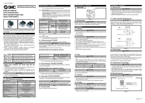
Instruction Manual 3 Port Solenoid ValveSeries VK300The intended use of this product is to control the movement of an actuator.1 Safety InstructionsThese safety instructions are intended to prevent hazardous situations and/or equipment damage. These instructions indicate the level of potential hazard with the labels of “Caution,” “Warning” or “Danger.”They are all important notes for safety and must be followed in addition to International Standards (ISO/IEC) *1), and other safety regulations. *1)ISO 4414: Pneumatic fluid power - General rules relating to systems. ISO 4413: Hydraulic fluid power - General rules relating to systems.IEC 60204-1: Safety of machinery - Electrical equipment of machines. (Part 1: General requirements)ISO 10218-1: Robots and robotic devices - Safety requirements for industrial robots - Part 1: Robots.• Refer to product catalogue, Operation Manual and Handling Precautions for SMC Products for additional information. • Keep this manual in a safe place for future reference.Caution Caution indicates a hazard with a low level of risk which, if not avoided, could result in minor or moderate injury. WarningWarning indicates a hazard with a medium level of risk which, if not avoided, could result in death or serious injury. DangerDanger indicates a hazard with a high level of risk which, if not avoided, will result in death or serious injury.Warning• Always ensure compliance with relevant safety laws and standards.• All work must be carried out in a safe manner by a qualified person in compliance with applicable national regulations.• If this equipment is used in a manner not specified by the manufacturer, the protection provided by the equipment may be impaired.CautionThe product is provided for use in manufacturing industries only. Do not use in residential premises.2 Specifications2.1 Valve specificationFluidAir Operatingpressure range [MPa] Standard 0 to 0.7Low wattage (Y) Continuous duty (E) Flow characteristicsRefer to catalogue Ambient and fluid temperature [°C] -5 to 50 (no freezing) Response Time (at 0.5 MPa) [ms] Note 1) ≤10 (Standard)≤15 (Low power consumption type)Duty cycleContact SMC Minimum operating frequency1 cycle / 30 daysMaximum operating frequency [Hz] 10Manual override Non-locking push typeLubricationNot required Impact / Vibration resistance [m/s 2] Note 2) 300 / 50EnclosureIP30 (based on IEC60529)2 Specifications - continuedMounting orientation UnrestrictedWeight [g]VK332#: 80 VK334#: 120Table 1.Note 1) Based on dynamic performance test, JIS B 8419: 2010. (Coil temperature:20°C, at rated voltage, without surge suppressor).Note 2) Impact resistance: No malfunction occurred when it is tested with a droptester in the axial direction and at the right angles to the main valve and armature in both energized and de-energized states every once for each condition. (Values quoted are for a new valve).Vibration resistance : No malfunction occurred in a one-sweep test between 45 and 2000 Hz. Test was performed at both energized states in the axial direction and at the right angles to the main valve and armature. (Values quoted are for a new valve).2.2 Solenoid specificationElectrical entryGrommet (G, H), DIN terminal (D,DO)Rated coil voltage [V]AC (50 / 60 Hz) 100, 110, 200, 220, 240DC 12, 24Allowable voltage fluctuation Note1) ±10% of rated voltageApparentpower[VA]Note2) Standardtype Inrush 50 Hz 9.560 Hz 8 Holding50 Hz 760 Hz 5Power consumption [W] Without indicator light4 With indicator light 4.3Surge voltagesuppressor AC Varistor DC Diode (12 VDC or less: Varistor)Indicator lightAC Neon bulbDC LEDTable 2. Note 1) Valve state is not defined if electrical input is outside of specified operatingranges.Note 2) At the rated voltage.2.3 Low wattage VK33# (Y, W) and continuous duty VK33#E types • Specifications different from standard are as follows:Apparent power [VA]ACInrush50 Hz 3.560 Hz 3.3 Holding50 Hz 3 60 Hz2.8Power consumption [W]DCWithout indicator light: 2 With indicator light: 2.3Table 3.Caution• If the valve is to be energized for periods of long ON time, continuous duty VK33#E type is recommended. This model is for continuous duty, not for high cycle rates. But even in low cycle rates, if energizing the valve for more than one once a day, please contact SMC. 2.4 Vacuum type VK33# (V, W)• In contrast to the standard product, this vacuum model has less air leakage at low pressures, a feature that should be taken into consideration when using this valve for vacuum applications. • Specifications different from standard are as follows:Operating pressure range [MPa]-101.2 kPa to 0.1Table 4.Caution• Since this valve has slight air leakage, it cannot be used for vacuum holding (including positive pressure holding) in the pressure container. 2.5 Light indicationFigure 1.2 Specifications - continued2.6 Special productsWarningSpecial products (-X) might have specifications different from those shown in this section. Contact SMC for specific drawings.3 Installation3.1 InstallationWarning• Do not install the product unless the safety instructions have been read and understood.• When mounting a valve on the manifold base or sub-plate, etc., the mounting orientation is already decided. If mounted in a wrong direction, the equipment to be connected may result in malfunction (see Figures 10 and 11 under section 3.13). VK300 series valves can be mounted on the manifold base VV5K3 of VK3000 series. Refer to catalogue for more details.3.2 EnvironmentWarning• Do not use in an environment where corrosive gases, chemicals, salt water or steam are present.• Do not use in an explosive atmosphere.• Do not expose to direct sunlight. Use a suitable protective cover.• Do not install in a location subject to vibration or impact in excess of the product’s specifications .• Do not mount in a location exposed to radiant heat that would result in temperatures in excess of the product’s specifications.• When the solenoid valve is mounted in a control panel or it is energized for a long time, make sure that the ambient temperature is within the specification of the valve.• If using in an atmosphere where there is possible contact with water droplets, oil, weld spatter, etc., take suitable preventive measures. • Do not use in high humidity environment where condensation can occur.• Contact SMC for altitude limitations. 3.3 PipingCaution• Before connecting piping make sure to clean up chips, cutting oil, dust etc.• When installing piping or fittings, ensure sealant material does not enter inside the port. When using seal tape, leave 1 thread exposed on the end of the pipe/fitting.• Tighten fittings to the specified tightening torque.Port Connection thread size(R, NPT) Tightening Torque[N∙m ] 1(P), 2(A), 3(R)M5 1 to 1.5 1/83 to 5Table 5.3.4 LubricationCaution• SMC products have been lubricated for life at manufacture, and do not require lubrication in service.• If a lubricant is used in the system, refer to catalogue for details.3.5 Air supplyWarning• Use clean air. If the compressed air supply includes chemicals, synthetic materials (including organic solvents), salinity, corrosive gas etc., it can lead to damage or malfunction.Caution• Install an air filter upstream of the valve. Select an air filter with a filtration size of 5 μm or smaller. 3.6 Effect of back pressure when using a manifoldCaution• Use caution when valves are used on a manifold, because an actuator may malfunction or unexpected movement may occur due to back pressure.• For single acting cylinder, take appropriate measures to prevent malfunction by using it with an individual exhaust manifold.3 Installation - continued3.7 Light/surge voltage suppressor3.7.1 AC circuitGrommet (G)DIN Terminal (D)Standard type:VContinuous dutytype: EStandard type:VContinuous dutytype: EWithout Indicator Light: S(G, GS)(D, DS)With indicator light: ZNoneFigure 2.3.7.2 DC circuit (24V, 48V)Grommet (G)DIN Terminal (D)Standard type:Y, V, W Continuous dutytype: EStandard type:Y, V, W Continuous dutytype: EWithout Indicator Light: SWith Indicator Light : ZNoneFigure 3.3.7.3 DC circuit (6V, 12V)Grommet (G)DIN Terminal (D)Standard type:Y, V, WContinuous dutytype: EStandard type:Y, V, WContinuous dutytype: EWithout Indicator Light: SWith Indicator Light: ZNoneFigure 4.CautionIn the case of valves without surge suppressor, the machine designer shall add suppression as close as possible to the valve.ORIGINAL INSTRUCTIONSBody portedBase mountedV a r i s t o rC o i lC o i lC o i lC o i lD i o d e1 D i o d eV a r i s t o r122C o i lNeon bulb V a r i s t o r112Neon bulbD i o d eC o i lRed (+)Black (-)1 (+)2 (-)1 (+)2 (-)21122C o i lC o i lC o i lD i o d eD i o d eD i o d eLED C o i lC o i lV a r i s t o rV a r i s t o rC o i lLight (built-in connector) DIN type onlyFigure 5.Figure 6.3.8 Residual voltage of the surge voltage suppressorCaution• If a varistor or diode surge voltage suppressor is used, the suppressor arrests the back EMF voltage from the coil to approximately 1 V.• Ensure the transient voltage is within the specification of the host controller.• Valve response time is dependent on surge suppression method selected. 3.9 Countermeasure for surge voltageCaution• At times of sudden interruption of the power supply, the energy stored in a large inductive device may cause non-polar type valves in a de-energized state to switch.• When installing a breaker circuit to isolate the power, consider a valve with polarity (with polarity protection diode), or install a surge absorption diode across the output of the breaker. 3.10 How to wire DIN terminal wiring Caution• Use heavy duty cable with O.D. of Ø3.5 mm to Ø7 mm, otherwise it will not meet the IP65 (enclosure) standard (reference: 0.5 mm 2 2 core and 3 core wires equivalent to JIS C 3306).• Tighten the ground nut and set screw within the specified torque range.Figure 7.Figure 8. DIN type C• Refer to catalogue for additional details.3.10.1 Circuit with indicator light for DIN terminalFigure 9.3.10.2 Changing cable entry directionCaution• After separating terminal block and housing, the cable entry direction can be changed by attaching the housing in the desired direction (4 directions in 90 degree increments).• In the case of valve with indicator light, avoid damaging the light with lead wire . 3.11 Extended periods of continuous energizationWarningIf a valve is energized continuously for a long period of time or is mounted in a control panel, the rise in temperature due to heat rise of the coil assembly may cause a decline in solenoid valve performance, reduce service life, or have adverse effects on peripheral equipment. If the valve is to be energized continuously for a long period of time, be sure to use the continuous duty type (VK33#E). 3.12 Manual overrideWarningRegardless of an electric signal for the valve, the manual override is used for switching the main valve. Connected actuator is started by manual operation. Only use the manual override after confirming that there is nodanger.3.13 Mounting and removal of valves• Tighten the valve mounting screw and bracket screw (if required) to the appropriate tightening torque of 0.6 N·m.• Refer catalogue for details of mounting and removal of valves from manifold.Figure 10.Figure 11.4 How to OrderRefer to catalogue for ‘How to order’ or product drawing for special products.5 Outline Dimensions (mm)Refer to catalogue for outline dimensions.6 Maintenance6.1 General maintenanceCaution• Not following proper maintenance procedures could cause the product to malfunction and lead to equipment damage.• If handled improperly, compressed air can be dangerous.• Maintenance of pneumatic systems should be performed only by qualified personnel.• Before performing maintenance, turn off the power supply and be sure to cut off the supply pressure. Confirm that the air is released to atmosphere.• After installation and maintenance, apply operating pressure and power to the equipment and perform appropriate functional and leakage tests to make sure the equipment is installed correctly.• If any electrical connections are disturbed during maintenance, ensure they are reconnected correctly and safety checks are carried out as required to ensure continued compliance with applicable national regulations.• Do not make any modification to the product.• Do not disassemble the product, unless required by installation or maintenance instructions.7 Limitations of UseWarningThe system designer should determine the effect of the possible failure modes of the product on the system.7.1 Limited warranty and disclaimer/compliance requirements Refer to Handling Precautions for SMC Products.7.2 Breathing holeCautionFigure 12.There is a breathing hole on the bottom surface of the valve. Please note that liquid may enter or block the breathing hole, which may cause malfunction.7.3 Leakage voltageCautionEnsure that any leakage voltage caused by the leakage current when the switching element is OFF causes ≤2% (for DC coils) or ≤20% (for AC coils) of rated voltage across the valve. 7.4 Low temperature operationCautionUnless otherwise indicated in the specifications for each valve, operation is possible to -5˚C , but appropriate measures should be taken to avoid solidification or freezing of drainage and moisture, etc.7.5 Holding of pressure (including vacuum)WarningSince valves are subject to air leakage, they cannot be used for applications such as holding pressure (including vacuum) in a system. 7.6 Cannot be used as an emergency shut-off valveWarningThis product is not designed for safety applications such as an emergency shut-off valve. If the valves are used in this type of system, other reliable safety assurance measures should be adopted. 7.7 Safety relays or PLCWarningIf a safe output from a safety relay or PLC is used to operate this valve, ensure that any output test pulse duration is shorter than 1 ms to avoid the valve solenoid responding. 7.8 Spring returned spool valvesWarning• The use of 2-position single valves with spring returned spools has to be carefully considered.• The return of the valve spool into the de-energized position depends on the pilot pressure. If the pilot pressure drops below the specified operating pressure the position of the spool cannot be defined. The design of the system must take into account such behaviour.• Additional measures might be necessary. For example, the installation of an additional air tank to maintain the pilot pressure.8 Product DisposalThis product shall not be disposed of as municipal waste. Check your local regulations and guidelines to dispose this product correctly, in order to reduce the impact on human health and the environment.9 ContactsRefer to or www.smc.eu for your local distributor/importer.URL : https:// (Global) https:// www.smc.eu (Europe) SMC Corporation, 4-14-1, Sotokanda, Chiyoda-ku, Tokyo 101-0021, JapanSpecifications are subject to change without prior notice from the manufacturer. © 2021 SMC Corporation All Rights Reserved. Template DKP50047-F-085MPPPPPP R NLLEDR RLED D NL: Neon bulb R: ResistorLED: Light emittingdiodeR: ResistorD: Protective diodeLED: Light emitting diode R: ResistorRed (+) Black (-) Surge voltage suppressorMarkingIndicator light (Built-in connector)Surge voltage suppressor(Built-in terminal)Marking AC, 12 VDC or less for DCFor 24 V or more Compatible cable: of Ø3.5 mm to Ø7mmGround nutTightening torque WasherGrommet (Rubber) (Voltage symbol) Terminal screw (3 positions)Tightening torque 0.2 N·m to 0.25 N·mHolding screw Tightening torque 0.3 N·m to 0.4 N·m Housing (Position for light mounting) Terminal block Slot area(+)(-)Bleed hole1.65 N·m to2.5 N·mN·m P RRPRRP RRPR PR RRPR RPRRPPPPPGround。