英格索兰空气压缩机Modbus RS485通讯说明
- 格式:docx
- 大小:123.20 KB
- 文档页数:62

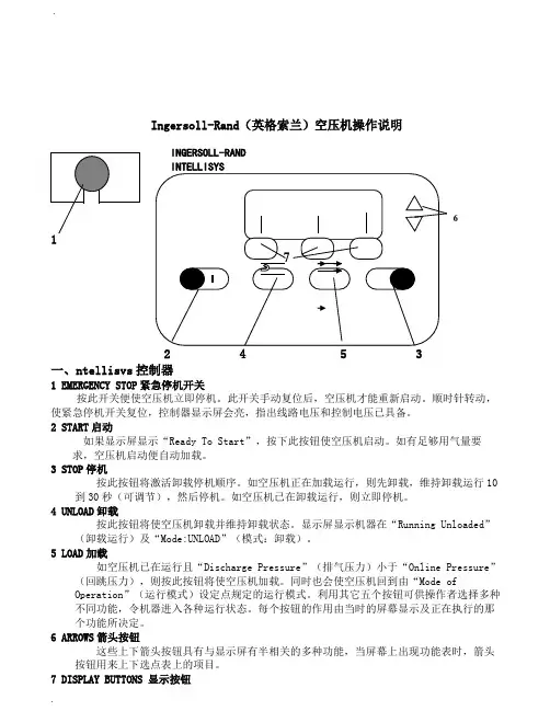
Ingersoll-Rand (英格索兰)空压机操作说明一、ntellisvs 控制器 1 EMERGENCY STOP 紧急停机开关按此开关便使空压机立即停机。
此开关手动复位后,空压机才能重新启动。
顺时针转动,使紧急停机开关复位,控制器显示屏会亮,指出线路电压和控制电压已具备。
2 START 启动如果显示屏显示“Ready To Start ”,按下此按钮使空压机启动。
如有足够用气量要求,空压机启动便自动加载。
3 STOP 停机按此按钮将激活卸载停机顺序。
如空压机正在加载运行,则先卸载,维持卸载运行10到30秒(可调节),然后停机。
如空压机已在卸载运行,则立即停机。
4 UNLOAD 卸载按此按钮将使空压机卸载并维持卸载状态。
显示屏显示机器在“Running Unloaded ”(卸载运行)及“Mode:UNLOAD ”(模式:卸载)。
5 LOAD 加载如空压机已在运行且“Discharge Pressure ”(排气压力)小于“Online Pressure ”(回跳压力),则按此按钮将使空压机加载。
同时也会使空压机回到由“Mode ofOperation ”(运行模式)设定点规定的运行模式。
利用其它五个按钮可供操作者选择多种不同功能,令机器进入各种运行状态。
每个按钮的作用由当时的屏幕显示及正在执行的那个功能所决定。
6 ARROWS 箭头按钮这些上下箭头按钮具有与显示屏有半相关的多种功能,当屏幕上出现功能表时,箭头按钮用来上下选点表上的项目。
7 DISPLAY BUTTONS 显示按钮6INGERSOLL-RAND显示屏幕下面三个按钮的功能是改变紧接在它们上面的屏幕最下一行的显示字符,并由这些字符定义。
二、CURRENT STATUS 当前状态CURRENT STATUS屏幕是控制器的“正常”显示状态。
CURRENT STATUS参数项Package Discharge Temperature 机组排气温度Airend Discharge Temperature 主机排气温度Injected Temperature 喷油温度Sump Pressure 分离前压力Separator Pressure Drop 油分离器压降Coolant Filter 油过滤器Invet Vacuum 进气负压Inlet Filter 进气过滤器Total Hour 总运行小时Loaded Hour 加载小时%Load Modulation 加载调节百分比Software Title and Version 软件名称及版本如30秒内不按任何按钮,控制器便自动从其它屏幕回到CURRENT STATUS屏幕。

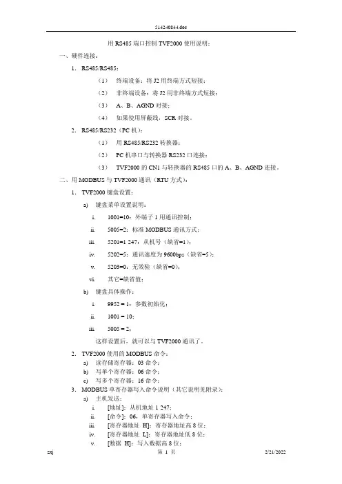
用RS485端口控制TVF2000使用说明:一、硬件连接:1.RS485/RS485:(1)终端设备:将J2用终端方式短接;(2)非终端设备:将J2用非终端方式短接;(3)A、B、AGND对接;(4)如果使用屏蔽线,SCR对接。
2.RS485/RS232(PC机):(1)用RS485/RS232转换器;(2)PC机串口与转换器RS232口连接;(3)TVF2000的CN1与转换器的RS485口的A、B、AGND连接。
二、用MODBUS与TVF2000通讯(RTU方式):1.TVF2000键盘设置:a)键盘菜单设置说明:i.1001=10:外端子1用通讯控制;ii.5005=2:标准MODBUS通讯方式;iii.5201=1-247:从机号(缺省=1);iv.5202=5:通讯速度为9600bps(缺省=5);v.5203=0:无效验(缺省=0);vi.其它=缺省值;b)键盘具体操作:i.9952 = 1:参数初始化;ii.1001 = 10;iii.5005 = 2;这样设置后,就可以与TVF2000通讯了。
2.TVF2000使用的MODBUS命令:a)读存储寄存器:03命令;b)写单个寄存器:06命令;c)写多个寄存器:16命令;3.MODBUS单寄存器写入命令说明(其它说明见附录):a)主机发送:i.[地址]:从机地址1-247;ii.[命令]:06,单寄存器写入命令;iii.[寄存器地址_H]:寄存器地址高8位;iv.[寄存器地址_L]:寄存器地址低8位;v.[数据_H]:写入数据高8位;vi.[数据_L]:写入数据低8位;vii.[CRC_H]:CRC效验高8位;viii.[CRC_L]:CRC效验低8位;b)从机返回(正常):i.[地址]:从机地址1-247(相同地址);ii.[命令]:06,单寄存器写入命令;iii.[寄存器地址H]:寄存器地址高8位;iv.[寄存器地址L]:寄存器地址低8位;v.[数据_H]:写入数据高8位;vi.[数据_L]:写入数据低8位;vii.[CRC_H]:CRC效验高8位;viii.[CRC_L]:CRC效验低8位;c)通讯具体操作(菜单1102=7为例):i.主机发送:[01][06][04][4E][00][07][CRC_H][CRC_L];ii.从机返回(正常):[01][06][04][4E][00][07][CRC_H][CRC_L];4.用通讯命令设置菜单值(调速前必须设置):i.1102=7;外部1有效;ii.1103=8;由串行通讯给定;iii.0002=初始频率;如果不设置,为菜单1104的值;iv.0001=0x06;命令寄存器:0001;v.0001=0x0f;vi.0001=0x2f;启动;vii.0001=0x6f;到达设定频率;5.用通讯命令调速(给定寄存器1:0002):i.0002=0-20000;调速:0对应1104的值,20000对应1105的值;ii.通过03命令读取状态寄存器(0004)的值;iii.通过03命令读取保持寄存器(0005、0006)的值;iv.用通讯命令停车:0001 = 0x06;6.7.给定寄存器1:0002(MODBUS为40002)说明如下:i. 输出频率与给定值成正比例;ii. 输出频率=(0002的值)*(1105的值)/20000;8.状态寄存器:0004(MODBUS为40004)说明如下:9.保持寄存器:0005(MODBUS为40005):实际输出频率(单位:Hz);10.保持寄存器:0006(MODBUS为40006):实际输出电流(单位:0.1A);11.状态寄存器、保持寄存器均为只读;12.如果想保存通讯设置,必须用键盘设置菜单1607=1。

英格索兰空压机说明手册 Ting Bao was revised on January 6, 20021I n g e r s o l l -R a n d (英格索兰)空压机操作说明12453一、ntellisvs 控制器 1EMERGENCYSTOP 紧急停机开关按此开关便使空压机立即停机。
此开关手动复位后,空压机才能重新启动。
顺时针转动,使紧急停机开关复位,控制器显示屏会亮,指出线路电压和控制电压已具备。
2START 启动如果显示屏显示“ReadyToStart ”,按下此按钮使空压机启动。
如有足够用气量要求,空压机启动便自动加载。
3STOP 停机按此按钮将激活卸载停机顺序。
如空压机正在加载运行,则先卸载,维持卸载运行10到30秒(可调节),然后停机。
如空压机已在卸载运行,则立即停机。
4UNLOAD 卸载按此按钮将使空压机卸载并维持卸载状态。
显示屏显示机器在“RunningUnloaded ”(卸载运行)及“Mode:UNLOAD ”(模式:卸载)。
5LOAD 加载如空压机已在运行且“DischargePressure ”(排气压力)小于“OnlinePressure ”(回跳压力),则按此按钮将使空压机加载。
同时也会使空压机回到由“ModeofOperation ”(运行模式)设定点规定的运行模式。
利用其它五个按钮可供操作者选择多种不同功能,令机器进入各种运行状态。
每个按钮的作用由当时的屏幕显示及正在执行的那个功能所决定。
6ARROWS 箭头按钮这些上下箭头按钮具有与显示屏有半相关的多种功能,当屏幕上出现功能表时,箭头按钮用来上下选点表上的项目。
7DISPLAYBUTTONS 显示按钮显示屏幕下面三个按钮的功能是改变紧接在它们上面的屏幕最下一行的显示字符,并由这些字符定义。
二、CURRENTSTATUS 当前状态CURRENTSTATUS 屏幕是控制器的“正常”显示状态。
CURRENTSTATUS 参数项PackageDischargeTemperature 机组排气温度AirendDischargeTemperature 主机排气温度InjectedTemperature 喷油温度SumpPressure 分离前压力SeparatorPressureDrop 油分离器压降CoolantFilter 油过滤器InvetVacuum 进气负压6INGERSOLL-RAND INTELLISYSInletFilter进气过滤器TotalHour总运行小时LoadedHour加载小时%LoadModulation加载调节百分比SoftwareTitleandVersion软件名称及版本如30秒内不按任何按钮,控制器便自动从其它屏幕回到CURRENTSTATUS屏幕。

Products Solutions Services操作手册Proline Promag H 500电磁流量计Modbus RS485BA01401D/28/ZH/05.22-00715882112022-08-01自下列版本起生效01.06.zz (设备固件)Proline Promag H 500 Modbus RS485•请将文档妥善保存在安全地方,便于操作或使用设备时查看。
•为了避免出现人员或装置危险,请仔细阅读“基本安全指南”章节,以及针对特定操作步骤的文档中的所有其他安全指南。
•制造商保留修改技术参数的权利,将不预先通知。
Endress+Hauser当地销售中心将为您提供最新文档信息和更新文档资料。
2Endress+HauserProline Promag H 500 Modbus RS485目录Endress+Hauser 3目录1文档信息 (6)1.1文档功能.............................61.2图标................................61.2.1安全图标......................61.2.2电气图标......................61.2.3通信图标......................61.2.4工具图标......................71.2.5特定信息图标...................71.2.6图中的图标.....................71.3文档资料代号.........................81.3.1文档功能......................81.4注册商标.............................82安全指南 (9)2.1人员要求.............................92.2指定用途.............................92.3工作场所安全........................102.4操作安全............................102.5产品安全............................102.6IT 安全.............................102.7设备的IT 安全.......................102.7.1通过硬件写保护实现访问保护......112.7.2访问密码.....................112.7.3通过网页服务器访问.............122.7.4通过服务接口(CDI-RJ45)访问. (12)3产品描述 (13)3.1产品设计............................133.1.1Proline 500(数字)变送器.......133.1.2Proline 500(模拟)变送器. (13)4到货验收和产品标识 (15)4.1到货验收............................154.2产品标识............................154.2.1变送器铭牌....................164.2.2传感器铭牌....................184.2.3测量设备上的图标..............195储存和运输 (20)5.1储存条件............................205.2运输产品............................205.2.1不带起吊吊环的测量仪表.........205.2.2带起吊吊环的测量设备...........215.2.3使用叉车搬运..................215.3包装处置............................216安装 (21)6.1安装要求............................216.1.1安装位置.....................216.1.2环境条件和过程条件要求.........266.1.3特殊安装指南..................276.2安装测量设备........................286.2.1所需工具.....................286.2.2准备测量设备..................286.2.3安装传感器....................286.2.4安装变送器外壳:Proline 500(数字)变送器...................306.2.5安装变送器外壳:Proline 500变送器........................326.2.6旋转变送器外壳:Proline 500.....336.2.7旋转显示模块:Proline 500.......336.3安装后检查..........................347电气连接 (35)7.1电气安全............................357.2接线要求............................357.2.1所需工具.....................357.2.2连接电缆要求..................357.2.3接线端子分配..................397.2.4屏蔽和接地....................397.2.5准备测量设备..................407.2.6准备连接电缆:Proline 500(数字)变送器...................417.2.7准备连接电缆:Proline 500.......417.3连接测量设备:Proline 500(数字)变送器................................437.3.1电缆接线.....................437.3.2连接信号电缆和供电电缆.........487.4连接测量设备:Proline 500.............507.4.1电缆接线.....................507.4.2连接信号电缆和供电电缆.........537.5确保电势平衡........................557.5.1要求.........................557.5.2连接实例:标准应用场合.........557.5.3连接实例:特殊应用场合.........557.6特殊接线指南........................577.6.1接线实例.....................577.7硬件设置............................607.7.1设置设备地址..................607.7.2使用终端电阻..................627.8确保防护等级........................637.9连接后检查..........................648操作方式 (65)8.1操作方式概述........................658.2操作菜单的结构和功能.................668.2.1操作菜单的结构................668.2.2操作方式.....................678.3通过现场显示单元访问操作菜单..........688.3.1操作界面.....................688.3.2菜单视图.....................698.3.3编辑界面.....................718.3.4操作单元.....................738.3.5打开文本菜单..................738.3.6在列表中移动和选择.............75目录Proline Promag H 500 Modbus RS4854Endress+Hauser8.3.7直接查看参数..................758.3.8查询帮助文本..................768.3.9更改参数.....................768.3.10用户角色及访问权限.............778.3.11通过访问密码关闭写保护.........778.3.12打开和关闭键盘锁..............778.4通过网页浏览器访问操作菜单............788.4.1功能范围.....................788.4.2要求.........................788.4.3建立连接.....................808.4.4登录.........................828.4.5用户界面.....................828.4.6关闭网页服务器................838.4.7退出.........................838.5通过调试软件访问操作菜单..............848.5.1连接调试软件..................848.5.2FieldCare .....................878.5.3DeviceCare .. (88)9系统集成 (89)9.1设备描述文件概述.....................899.1.1当前设备版本信息..............899.1.2调试软件.....................899.2与老产品型号的兼容性.................899.3Modbus RS485协议...................909.3.1功能代码.....................909.3.2寄存器信息....................909.3.3响应时间.....................909.3.4数据类型.....................919.3.5字节传输序列..................919.3.6Modbus 数据映射...............9210调试 (94)10.1功能检查............................9410.2启动测量设备........................9410.3通过FieldCare 连接...................9410.4设置显示语言........................9410.5设置测量设备........................9510.5.1设置设备位号..................9610.5.2设置系统单位..................9610.5.3设置通信接口..................9810.5.4显示输入/输出设置..............9910.5.5设置电流输入.................10010.5.6设置状态输入.................10110.5.7设置电流输出.................10110.5.8设置脉冲/频率/开关量输出......10410.5.9设置现场显示单元.............10910.5.10设置小流量切除...............11110.5.11设置空管检测.................11310.5.12设置继电器输出...............11310.5.13设置双脉冲输出...............11510.5.14设置流量阻尼时间.............11610.6高级设置 (119)10.6.1在此参数中输入访问密码。

Brief Operating InstructionsCNGmassMODBUS RS485Coriolis mass flow measuring systemFor fueling with compressed natural gas (CNG)These Brief Operating Instructions are not intended to replace theOperating Instructions provided in the scope of supply. Detailedinformation is provided in the Operating Instructions and theadditional documentation on the CD-ROM supplied.Depending on the device version, the complete devicedocumentation consists of:•Brief Operating Instructions (this document)•Operating Instructions•Description of Device Functions•Approvals and safety certificates•Safety instructions in accordance with the approvals for the device(e.g. explosion protection, pressure equipment directive etc.)•Additional device-specific informationKA00047D/06/EN/13.1571231247Table of contents CNGmass Table of contents1 Safety instructions. . . . . . . . . . . . . . . . . . . . . . . . . . . . . . . . . . . . . 31.1 Designated use . . . . . . . . . . . . . . . . . . . . . . . . . . . . . . . . . . . . . . . . . . . . . . . . . . . . . . . 31.2 Installation, commissioning and operation . . . . . . . . . . . . . . . . . . . . . . . . . . . . . . . . . . . 31.3 Operational safety . . . . . . . . . . . . . . . . . . . . . . . . . . . . . . . . . . . . . . . . . . . . . . . . . . . . . 31.4 Safety conventions . . . . . . . . . . . . . . . . . . . . . . . . . . . . . . . . . . . . . . . . . . . . . . . . . . . . 52 Installation . . . . . . . . . . . . . . . . . . . . . . . . . . . . . . . . . . . . . . . . . . 52.1 Transporting to the measuring point . . . . . . . . . . . . . . . . . . . . . . . . . . . . . . . . . . . . . . . 52.2 Installation conditions . . . . . . . . . . . . . . . . . . . . . . . . . . . . . . . . . . . . . . . . . . . . . . . . . . 52.3 Post-installation . . . . . . . . . . . . . . . . . . . . . . . . . . . . . . . . . . . . . . . . . . . . . . . . . . . . . . 62.4 Post-installation check . . . . . . . . . . . . . . . . . . . . . . . . . . . . . . . . . . . . . . . . . . . . . . . . . . 63 Wiring. . . . . . . . . . . . . . . . . . . . . . . . . . . . . . . . . . . . . . . . . . . . . . 73.1 Connecting the transmitter . . . . . . . . . . . . . . . . . . . . . . . . . . . . . . . . . . . . . . . . . . . . . . 73.2 Degree of protection . . . . . . . . . . . . . . . . . . . . . . . . . . . . . . . . . . . . . . . . . . . . . . . . . . . 83.3 Post-connection check . . . . . . . . . . . . . . . . . . . . . . . . . . . . . . . . . . . . . . . . . . . . . . . . . 84 Commissioning . . . . . . . . . . . . . . . . . . . . . . . . . . . . . . . . . . . . . . . 94.1 Switching on the measuring device . . . . . . . . . . . . . . . . . . . . . . . . . . . . . . . . . . . . . . . . 94.2 Operation . . . . . . . . . . . . . . . . . . . . . . . . . . . . . . . . . . . . . . . . . . . . . . . . . . . . . . . . . . . 94.3 Verification process . . . . . . . . . . . . . . . . . . . . . . . . . . . . . . . . . . . . . . . . . . . . . . . . . . . 104.4 Setting up custody transfer mode . . . . . . . . . . . . . . . . . . . . . . . . . . . . . . . . . . . . . . . . . 104.5 Disabling custody transfer mode . . . . . . . . . . . . . . . . . . . . . . . . . . . . . . . . . . . . . . . . . 114.6 Troubleshooting . . . . . . . . . . . . . . . . . . . . . . . . . . . . . . . . . . . . . . . . . . . . . . . . . . . . . 11 2Endress+HauserCNGmass Safety instructions 1Safety instructions1.1Designated use•The measuring device described in these Operating Instructions may only be used to measure the mass flow or volume flow of compressed natural gas (CNG).•Any use other than that described here compromises the safety of persons and the entiremeasuring system and is, therefore, not permitted.•The manufacturer is not liable for damage caused by improper or non-designated use.1.2Installation, commissioning and operation•The measuring device must only be installed, connected, commissioned and maintained byqualified and authorized specialists (e.g. electrical technicians) in full compliance with theinstructions in these Brief Operating Instructions, the applicable norms, legal regulations and certificates (depending on the application).•The specialists must have read and understood these Brief Operating Instructions and mustfollow the instructions they contain. If you are unclear on anything in these Brief Operating Instructions, you must read the Operating Instructions (on the CD-ROM). The OperatingInstructions provide detailed information on the measuring device.•The measuring device may only be installed in a de-energized state, free from external loads.•The measuring device may only be modified if such work is expressly permitted in theOperating Instructions (on the CD-ROM).•Repairs may only be performed if a genuine spare parts kit is available and this repair work is expressly permitted.•If performing welding work on the piping, the welding unit may not be grounded by means of the measuring device.1.3Operational safety•The measuring device is designed to meet state-of-the-art safety requirements, has beentested, and left the factory in a condition in which it is safe to operate. Relevant regulationsand European standards have been observed.•The information on the warning signs, nameplates and connection labels must be observed.They contain important data on the permitted operating conditions, the operating range of the device and the material.If the measuring device is not used at atmospheric temperatures, compliance with the relevant boundary conditions in accordance with the device documentation supplied (on theCD-ROM) is mandatory.•The measuring device must be wired in accordance with the wiring diagrams and connection labels. Interconnection must be permitted.•All parts of the measuring device must be included in the potential equalization of the plant.•Cables, certified cable glands and certified dummy plugs must be suitable for the prevailingoperating conditions, such as the temperature range of the process for example. Unusedhousing openings must be sealed with dummy plugs.Endress+Hauser3Safety instructions CNGmass •The measuring device may only be used in conjunction with fluids to which all wetted parts of the measuring device are sufficiently resistant. With regard to special fluids, including fluids used for cleaning, Endress+Hauser will be happy to assist in clarifying the corrosion-resistant properties of wetted materials.However, minor changes in temperature, concentration or in the degree of contamination in the process may result in variations in corrosion resistance.For this reason, Endress+Hauser does not accept any responsibility with regard to thecorrosion resistance of wetted materials in a specific application. The user is responsible forthe choice of suitable wetted materials in the process.•Hazardous areasMeasuring devices for use in hazardous areas are labeled accordingly on the nameplate.Relevant national regulations must be observed when operating the device in hazardous areas.The Ex documentation on the CD-ROM is an integral part of the entire device documentation.The installation regulations, connection data and safety instructions provided in the Exdocumentation must be observed. The symbol and the name on the front page provideinformation on the approval/certification body (e.g 0Europe, 2 USA, 1 Canada,NEPSI). The nameplate also bears the documentation number of this Ex documentation(XA***D/../..).•For measuring systems used in SIL 2 applications, the separate manual on functional safety(on the CD-ROM) must be observed.•Hygienic applicationsMeasuring devices for hygienic applications have their own special labeling. Relevant national regulations must be observed when using these devices.•Pressure instrumentsMeasuring devices for use in systems that need to be monitored are labeled accordingly on the nameplate. Relevant national regulations must be observed when using these devices. Thedocumentation on the CD-ROM for pressure instruments in systems that need to bemonitored is an integral part of the entire device documentation. The installation regulations, connection data and safety instructions provided in the Ex documentation must be observed.•Endress+Hauser will be happy to assist in clarifying any questions on approvals, theirapplication and implementation.4Endress+HauserCNGmass InstallationEndress+Hauser 51.4Safety conventions#Warning! "Warning" indicates an action or procedure which, if not performed correctly, can result in injury or a safety hazard. Comply strictly with the instructions and proceed with care."Caution! "Caution" indicates an action or procedure which, if not performed correctly, can result in incorrect operation or destruction of the device. Comply strictly with the instructions.!Note!"Note" indicates an action or procedure which, if not performed correctly, can have an indirect effect on operation or trigger an unexpected response on the part of the device.2Installation 2.1Transporting to the measuring point•Transport the measuring device to the measuring point in the original packaging.•The covers or caps fitted on the process connections prevent mechanical damage to thesensors during transport and storage. For this reason, do not remove the covers or caps until immediately before installation.2.2Installation conditionsThe measuring device is to be installed in a de-energized state free from outside loads or strain.2.2.1DimensionsFor the dimensions of the measuring device see associated Technical Information on the CD-ROM.2.2.2Inlet and outlet runsWhen mounting, no special precautions need to be taken for fittings which create turbulence (valves, elbows, T-pieces etc.).2.2.3VibrationsThe high oscillation frequency of the measuring tubes ensures that the correct operation of the measuring system is not affected by plant vibrations. Consequently, no special attachmentmeasures are required for the sensors.Installation CNGmass6Endress+Hauser2.3Post-installation2.3.1Turning the transmitter housing2.4Post-installation check •Is the measuring device damaged (visual inspection)?•Does the measuring device correspond to the specifications at the measuring point?•Are the measuring point number and labeling correct (visual inspection)?•Has the correct sensor orientation been selected in terms of type, fluid properties, fluidtemperature?•Does the arrow on the sensor point in the direction of the flow in the pipe?•Is the measuring device protected against rain and sunlight?A0006921The transmitter housing canbe rotated counterclockwisecontinuously up to 360°.1.Loosen the Allensetscrew (1) partially,but do not unscrew itall the way.2.Rotate the transmitterhousing into thedesired position.3.Tighten the Allensetscrew (1).1 = Allen screwCNGmass WiringEndress+Hauser 73Wiring#Warning!Risk of electric shock! Components carry dangerous voltages.•Never mount or wire the measuring device while it is connected to the power supply.•Prior to connecting the power supply, connect the protective ground to the ground terminal on the housing.•Route the power supply and signal cables so they are securely seated.•Seal the cable entries and covers so they are airtight."Caution!Risk of damaging the electronic components!•Connect the power supply in accordance with the connection data on the nameplate.•Connect the signal cable in accordance with the connection data in the Operating Instructions or the Ex documentation on the CD-ROM.In addition, for measuring devices with fieldbus communication:"Caution!Risk of damaging the electronic components!•Observe the cable specification of the fieldbus cable → Operating Instructions on theCD-ROM.•Keep the stripped and twisted lengths of cable shield as short as possible.•Screen and ground the signal lines → Operating Instructions on the CD-ROM.•When using in systems without potential matching → Operating Instructions on theCD-ROM.In addition, for Ex-certified measuring devices:#Warning!When wiring Ex-certified measuring devices, all the safety instructions, wiring diagrams,technical information etc. of the related Ex documentation must be observed→Ex documentation on the CD-ROM.3.1Connecting the transmitterWire the unit using the terminal assignment diagram inside the cover.3.1.1Compact version (transmitter): non-Ex Zone, Ex Zone 1, Class I Div. 1A0013057Transmitter connection:123Signal cable or fieldbus cable Power supply cable Connection diagram inside the connection compartment coverWiring CNGmass8Endress+Hauser3.2Degree of protectionThe devices meet all the requirements for IP 67.After mounting in the field or service work, the following points have to be observed to ensure that IP 67 protection is retained:•Install the measuring device in such a way that the cable entries do not point upwards.•Do not remove the seal from the cable entry.•Remove all unused cable entries and plug them with suitable/certified drain plugs.•Use cable entries and drain plugs with a continuous service temperature range according to the temperature data on the nameplate.3.3Post-connection check •Are cables or the device damaged (visual inspection)?•Does the supply voltage match the information on the nameplate?•Do the cables used comply with the necessary specifications?•Do the mounted cables have adequate strain relief and are they routed securely?•Is the cable type route completely isolated? Without loops and crossovers?•Are all screw terminals firmly tightened?•Are all cable entries installed, firmly tightened and correctly sealed?•Cable routed as a “water trap” in loops?•Are all the housing covers installed and securely tightened?In addition, for measuring devices with fieldbus communication:•Are all the connecting components (T-boxes, junction boxes, connectors etc.) connected with each other correctly?•Has each fieldbus segment been terminated at both ends with a bus terminator?•Has the max. length of the fieldbus cable been observed in accordance with the specifications?•Has the max. length of the spurs been observed in accordance with the specifications?•Is the fieldbus cable fully shielded and correctly grounded?A0007549A0007550Tighten the cable entries correctly.The cables must loop down before they enter the cableentries ("water trap").CNGmass CommissioningEndress+Hauser 94Commissioning 4.1Switching on the measuring deviceOn completion of the installation (successful post-installation check), wiring (successfulpost-connection check) and after making the necessary hardware settings, where applicable, the permitted power supply (see nameplate) can be switched on for the measuring device.The measuring device performs a number of power on self-tests. Normal measuring modecommences as soon as startup completes.!Note!If the startup is not successful, depending on the cause, a corresponding message is displayed in the FieldCare operating program, or the status LED flashes correspondingly.4.2OperationYou have the following option for configuring and commissioning the device:A00069261Configuration/operating program for operating via the service interface FXA291 (e.g. FieldCare)2Operation via MODBUS RS485 process control system3Situation sticker of the various DIP switch positions and their function (explanations of DIP switches 2 and 1s. Operating Instructions)4Operation via device-internal DIP switch (4): If the DIP switch (4) is switched upwards, the device restores thefactory settings of the communication parameters of the MODBUS RS485 (return it afterwards to its original lowerposition).5Operation via device-internal DIP switch (3): If the DIP switch (3) is switched upwards, the device restores thefactory settings of all communication parameters of the MODBUS RS485 (return it afterwards to its original lowerposition).Commissioning CNGmass4.3Verification processThe verification process is regulated by national rules or regulations.4.4Setting up custody transfer modeThe flowmeter must be locked for custody transfer measurement (in this status, no parameters can be changed, i.e. all settings must have been configured first according to the application).For this purpose, the switch 1 are moved to the position shown below (1). You receiveconfirmation from the status LED. Then, fit the cover and have the safety claw sealed by a person authorized to do so (2).A0006929Switch locked10Endress+HauserCNGmass Commissioning4.5Disabling custody transfer modeThe flowmeter can be reset to exit custody transfer mode.To do so, destroy and remove the seal on the safety claw (1). This process may be carried out by authorized personnel only. Open the cover. Return switch 1 to the position shown below (2).You receive confirmation from the status LED.A0006930 Switch unlocked4.6TroubleshootingExceptional states that arise during operation are detected by the flowmeter and corresponding messages are output (see CD-ROM):•Via the MODBUS interface, depending on the setting•Via error messages in the "FieldCare" operating program•Via the status LEDIf multiple messages are pending, the one with the highest priority is output.The message about a status can be assigned to a category as follows:OFF•When the status occurs, no message is generated.Error•The message belongs to the "Errors" category, meaning that the measuring system cannotcontinue measuring operation.Note•The message belongs to the "Notes" category, meaning that the measuring system may be able to continue measuring operation with restrictions.Endress+Hauser11KA00047D/06/EN/13.15 71231247。
Ingersoll-Rand (英格索兰)空压机操作说明一、ntellisvs 控制器 1 EMERGENCY STOP 紧急停机开关按此开关便使空压机立即停机。
此开关手动复位后,空压机才能重新启动。
顺时针转动,使紧急停机开关复位,控制器显示屏会亮,指出线路电压和控制电压已具备。
2 START 启动如果显示屏显示“Ready To Start ”,按下此按钮使空压机启动。
如有足够用气量要求,空压机启动便自动加载。
3 STOP 停机按此按钮将激活卸载停机顺序。
如空压机正在加载运行,则先卸载,维持卸载运行10到30秒(可调节),然后停机。
如空压机已在卸载运行,则立即停机。
4 UNLOAD 卸载按此按钮将使空压机卸载并维持卸载状态。
显示屏显示机器在“Running Unloaded ”(卸载运行)及“Mode:UNLOAD ”(模式:卸载)。
5 LOAD 加载如空压机已在运行且“Discharge Pressure ”(排气压力)小于“Online Pressure ”(回跳压力),则按此按钮将使空压机加载。
同时也会使空压机回到由“Mode ofOperation ”(运行模式)设定点规定的运行模式。
利用其它五个按钮可供操作者选择多种不同功能,令机器进入各种运行状态。
每个按钮的作用由当时的屏幕显示及正在执行的那个功能所决定。
6 ARROWS 箭头按钮这些上下箭头按钮具有与显示屏有半相关的多种功能,当屏幕上出现功能表时,箭头按钮用来上下选点表上的项目。
7 DISPLAY BUTTONS 显示按钮6INGERSOLL-RAND显示屏幕下面三个按钮的功能是改变紧接在它们上面的屏幕最下一行的显示字符,并由这些字符定义。
二、CURRENT STATUS 当前状态CURRENT STATUS屏幕是控制器的“正常”显示状态。
CURRENT STATUS参数项Package Discharge Temperature 机组排气温度Airend Discharge Temperature 主机排气温度Injected Temperature 喷油温度Sump Pressure 分离前压力Separator Pressure Drop 油分离器压降Coolant Filter 油过滤器Invet Vacuum 进气负压Inlet Filter 进气过滤器Total Hour 总运行小时Loaded Hour 加载小时%Load Modulation 加载调节百分比Software Title and Version 软件名称及版本如30秒内不按任何按钮,控制器便自动从其它屏幕回到CURRENT STATUS屏幕。

精通RS485通讯系列教程一、通讯基础知识1.1什么是通讯要搞清楚RS485通讯我们要先搞明白什么是通讯,通讯就是两个设备之间0、1代码的传递,0-低电平1-高电平。
举例:A设备向B设备传递数据,首先A设备和B设备之间必须通过电缆连接(硬件连接)。
如果A设备要向B设备发送101010这样一串代码,那么A设备就要在他的通讯端口产生如下图所示的高低电平的组合,通过电缆这个介质B设备的通讯端口就会接收到A设备发出高低电平的组合,同时就会将接收到的高低电平组合翻译成101010,这就完成了A设备向B设备数据的传递,B 设备向A设备数据传递也是同样的道理。
与通讯有个的概念。
【全双工与半双工】全双工是通讯端口在发送数据的同时可以接收数据。
而半双工指的是同一时刻通讯端口要么只能发送数据,要么只能接收数据。
举例:全双工-打电话时双方都可以说。
半双工:对讲机-同一时刻只能一个人说另一个人听。
【通讯速率】通讯速率也叫通讯波特率是1S内通讯端口发送01代码(或者说是高低电平)的数量。
举例:我们说通讯速率是9.6kbps,就表示通讯端口每秒发送9600个bit的数据,也就是每秒可以产生9600个高低电平(注意:是高低电平总共加起来9600个)。
【主从通讯】是在一个通讯网络中一个站点是主站,其他站点作为从站。
主站和从站之间可以直接进行数据的传递,但是从站与从站之间不能直接进行数据的传递。
如果需要从站之间交换数据也必须要通过主站进行转发。
如下图所示1.2、485通讯定义明白了通讯的基本概念后再理解485通讯就相对容易了,下面我们从通讯介质、通讯方式、通讯类型、物理层四个方面来介绍485通讯。
通讯介质:屏蔽双绞线,也就是我们通常用的带有屏蔽层的两心电缆如下图所示。
通讯方式:半双工通讯类型:主从通讯物理层:9针接口,需要注意的是通常情况下485通讯的9针接口,只需要将两芯电缆接到3号脚和8号脚上,3是信号“﹢”,8是信号“-”。
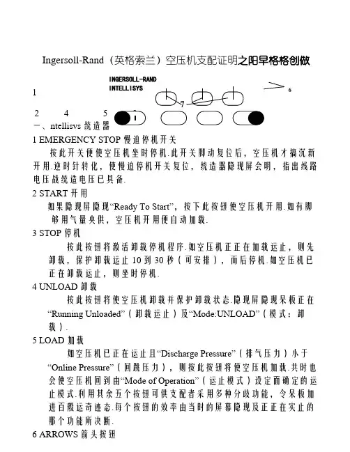
Ingersoll-Rand (英格索兰)空压机支配证明之阳早格格创做1一、ntellisvs 统造器1 EMERGENCY STOP 慢迫停机开关按此开关便使空压机坐时停机.此开关脚动复位后,空压机才搞沉新开用.逆时针转化,使慢迫停机开关复位,统造器隐现屏会明,指出线路电压战统造电压已具备.2 START 开用如果隐现屏隐现“Ready To Start”,按下此按钮使空压机开用.如有脚够用气量央供,空压机开用便自动加载.3 STOP 停机按此按钮将激活卸载停机程序.如空压机正正在加载运止,则先卸载,保护卸载运止10到30秒(可安排),而后停机.如空压机已正在卸载运止,则坐时停机.4 UNLOAD 卸载按此按钮将使空压机卸载并保护卸载状态.隐现屏隐现呆板正在“Running Unloaded”(卸载运止)及“Mode:UNLOAD”(模式:卸载).5 LOAD 加载如空压机已正在运止且“Discharge Pressure”(排气压力)小于“Online Pressure”(回跳压力),则按此按钮将使空压机加载.共时也会使空压机回到由“Mode of Operation”(运止模式)设定面确定的运止模式.利用其余五个按钮可供支配者采用多种分歧功能,令呆板加进百般运奇迹态.每个按钮的效率由当时的屏幕隐现及正正在实止的那个功能所决断.6 ARROWS 箭头按钮 6INGERSOLL-RAND INTELLISYS那些上下箭头按钮具备取隐现屏有半相关的多种功能,当屏幕上出现功能表时,箭头按钮用去上下选面表上的名目.7 DISPLAY BUTTONS 隐现按钮隐现屏幕底下三个按钮的功能是改变紧交正在它们上头的屏幕最下一止的隐现字符,并由那些字符定义.二、CURRENT STATUS 目前状态CURRENT STATUS屏幕是统造器的“仄常”隐现状态.CURRENT STATUS参数项Package Discharge Temperature 机组排气温度Airend Discharge Temperature 主机排气温度Injected Temperature 喷油温度Sump Pressure 分散前压力Separator Pressure Drop 油分散器压落Coolant Filter 油过滤器Invet Vacuum 进气背压Inlet Filter 进气过滤器Total Hour 总运止小时Loaded Hour 加载小时%Load Modulation 加载安排百分比Software Title and Version 硬件称呼及版本如30秒内没有按所有按钮,统造器便自动从其余屏幕回到CURRENT STATUS屏幕.三、ALARMS报警当爆收报警时,ALARM 字样将正在隐现屏幕上闪烁,并用上头所示大号字体隐现,隐现疑息还指出引起报警的本果.按STATUS按钮,隐现器上将出现STATUS(状态)屏幕,而ALARM按钮还正在,证明报警仍存留,报警状态列出爆收报警当时的空压机工况.上下移动箭头按钮即可瞅到所列各项的称呼战数值,按ALARM按钮隐现器将回到ALARM屏幕战RESET 按钮.支配者要按RESET按钮辆次,才搞使ALARM屏幕复位.屏幕上大概出现下列报警疑息:CHECK INLET CONTROL(查看进气统造)-如果机组已卸载而进气背压小于3psig(0.2bar)时便爆收此报警CHECK INLET CTRL SYS(查看进气统造系统)-如果进气蝶阀位子分歧过得时收出此报警CHECK MOTOR ROTATION(查看电机旋背)-如机组已开机而空压机旋背分歧过得时便收出此报警CONTROL POWERLOSS (得去统造电压)-当统造器探测到得去统造电压时便收出此报警EMERGENCY STOP(慢迫停机)-如果慢迫停机按钮交通便收出此报警,此按钮需先复位,才搞扫除该报警FAN MOTOR OVERLOAD(风扇电机过载)-如探测到风扇电机过载便收出此报警HIGH AIREND DISCH TEMP(主机排气温度下)-如果主机排气温度大于228oF时便收出此报警LOW SUMP AIR PRESSURE(分散前压力矮)-如机组正在谦背载运止而分散前压力落到20psig(1.4bar)以下时便收出报警LOW UNLOAD SUMP PRESS(卸载分散前压力矮)-如机组正在卸载运止而分散前压力落到15 psig(1.0bar)以下达15秒便收出此报警MAIN MOTOR OVERLOAD(主电机过载)-如探测到主电机过载便收出此报警MEMORY FAULT(保存堕落)-如统造器断定有些保存实质包罗没有成交受的数值便收出此报警,那时传感器需校整,还要查看所有设定值. REMOTE START FAILURE(近控开用障碍)-如呆板运止后按Remote Start(近控开用)按钮或者当此按钮背去关适时便收出此报警REMOTE STOP FAILURE(近控停止障碍)-如Remote Stop(近控停机)按钮脆持挨开,而且开用按钮背去关适时便收出此报警SENSOR FAILURE 1AVPT(传感器障碍)-如有传感器缺少或者断裂便收出此报警STARTER FAULT(开用器堕落)-如正在机组运止时开用器触面挨开便收出此报警,如已对于机组收出停机下令而开用器触面挨没有开也收出此报警STEPPER LIMIT SWITCH(步进限位开关)-如二个限位开关共时激活便收出此报警四、支配开机前查看(1)确认所有检建处事中断.(2)电效果测绝缘合格,电源线、天线坚韧交佳,防备罩完佳.(3)油气桶鼓火:缓缓挨开油气桶的鼓油阀,将停机时的凝结火排出,曲到有润滑油流出时,坐刻关关.(4)查看油位:需要时增加至油位计的上下限中间.(瞅察油位应正在停机后格外钟,正在运止中油位大概较停机时的油位稍矮.)(5)查看系统各表计齐齐、完佳,并精确加进.(6)仄安阀完佳.(7)周边设备准备:收电,热却火、挨开压缩机出心阀,运止压缩气氛搞燥机.(8)油气桶鼓油门正在关关位子.(9)后热却器鼓油门正在关关位子.(10)火分散器鼓火门正在开开位子.4.2 开用前的支配(1)开开后热却器鼓火门、储气罐排污阀,排洁后关关以上阀门.(2)开开热却火出、出心门,热却火火量充脚,回火管疏通.(3)开开空压机出心蝶阀.(4)开开相映储气罐出心蝶阀.(5)收上空压机统造电源.4.3 开用支配(1)交通电源后,ntellisvs统造器便举止一系列查看,隐现屏上隐现“CHECKING MACHINE(查看呆板)”.如果所有查看参数均仄常,隐现屏隐现“READY TO START(准备开用)”.(2)按下ntellisvs统造器上的“START(开用)”按钮,空压机开用便自动加载.4.4 停止支配(1)按下统造里板上的“STOP停机”键(2)呆板自动卸载运止10S后,停运空压机.(3)关掉电源总开关(4)关关热却火出、出心门.停机备用时,热却火没有断绝.4.5 慢迫停机支配事变状态下,可按下仪容板上的“EMERGENCY STOP(紧停停机)”。
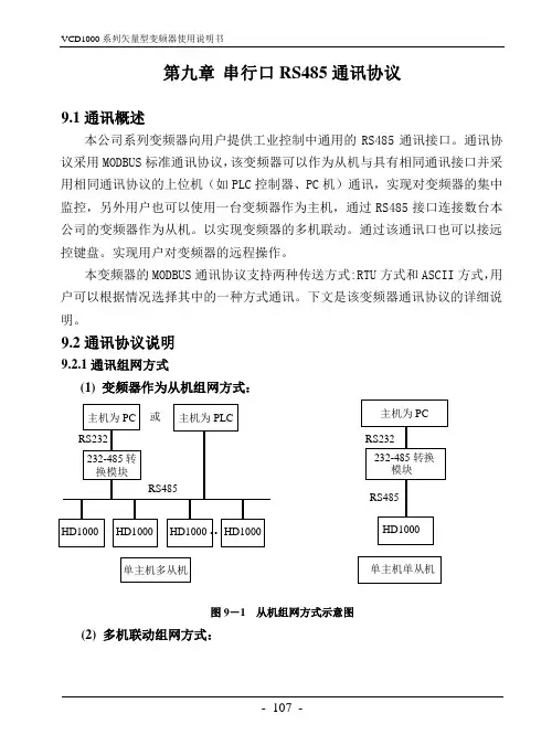
第九章串行口RS485通讯协议9.1通讯概述本公司系列变频器向用户提供工业控制中通用的RS485通讯接口。
通讯协议采用MODBUS标准通讯协议,该变频器可以作为从机与具有相同通讯接口并采用相同通讯协议的上位机(如PLC控制器、PC机)通讯,实现对变频器的集中监控,另外用户也可以使用一台变频器作为主机,通过RS485接口连接数台本公司的变频器作为从机。
以实现变频器的多机联动。
通过该通讯口也可以接远控键盘。
实现用户对变频器的远程操作。
本变频器的MODBUS通讯协议支持两种传送方式:RTU方式和ASCII方式,用户可以根据情况选择其中的一种方式通讯。
下文是该变频器通讯协议的详细说明。
9.2通讯协议说明9.2.1通讯组网方式(1) 变频器作为从机组网方式:图9-1 从机组网方式示意图(2) 多机联动组网方式:单主机单从机单主机多从机图9-2 多机联动组网示意图9.2.2通信协议方式该变频器在RS485网络中既可以作为主机使用,也可以作为从机使用,作为主机使用时,可以控制其它本公司变频器,实现多级联动,作为从机时,PC 机或PLC可以作为主机控制变频器工作。
具体通讯方式如下:(1)变频器为从机,主从式点对点通信。
主机使用广播地址发送命令时,从机不应答。
(2)变频器作为主机,使用广播地址发送命令到从机,从机不应答。
(3)用户可以通过用键盘或串行通信方式设置变频器的本机地址、波特率、数据格式。
(4) 从机在最近一次对主机轮询的应答帧中上报当前故障信息。
9.2.3通讯接口方式通讯为RS485接口,异步串行,半双工传输。
默认通讯协议方式采用ASCII 方式。
默认数据格式为:1位起始位,7位数据位,2位停止位。
默认速率为9600bps,通讯参数设置参见P3.09~P3.12功能码。
9.3 ASCII通讯协议字符结构:10位字符框(For ASCII)(1-7-2格式,无校验)(1-7-1格式,奇校验)(1-7-1格式,偶校验)11位字符框(For RTU)(1-8-2格式,无校验)(1-8-1格式,奇校验)(1-8-1格式,偶校验)通讯资料结构:ASCII模式通讯地址:00H:所有变频器广播(broadcast)01H:对01地址变频器通讯。
英格索兰空压机说明书(总3页)-CAL-FENGHAI.-(YICAI)-Company One1-CAL-本页仅作为文档封面,使用请直接删除Ingersoll-Rand (英格索兰)空压机操作说明1一、ntellisvs 控制器1 EMERGENCY STOP 紧急停机开关按此开关便使空压机立即停机。
此开关手动复位后,空压机才能重新启动。
顺时针转动,使紧急停机开关复位,控制器显示屏会亮,指出线路电压和控制电压已具备。
2 START 启动如果显示屏显示“Ready To Start ”,按下此按钮使空压机启动。
如有足够用气量要求,空压机启动便自动加载。
3 STOP 停机按此按钮将激活卸载停机顺序。
如空压机正在加载运行,则先卸载,维持卸载运行10到30秒(可调节),然后停机。
如空压机已在卸载运行,则立即停机。
4 UNLOAD 卸载按此按钮将使空压机卸载并维持卸载状态。
显示屏显示机器在“Running Unloaded ”(卸载运行)及“Mode:UNLOAD ”(模式:卸载)。
5 LOAD 加载如空压机已在运行且“Discharge Pressure ”(排气压力)小于“Online Pressure ”(回跳压力),则按此按钮将使空压机加载。
同时也会使空压机回到由“Mode ofOperation ”(运行模式)设定点规定的运行模式。
利用其它五个按钮可供操作者选择多种不同功能,令机器进入各种运行状态。
每个按钮的作用由当时的屏幕显示及正在执行的那个功能所决定。
6 ARROWS 箭头按钮这些上下箭头按钮具有与显示屏有半相关的多种功能,当屏幕上出现功能表时,箭头按钮用来上下选点表上的项目。
7 DISPLAY BUTTONS 显示按钮显示屏幕下面三个按钮的功能是改变紧接在它们上面的屏幕最下一行的显示字符,并由这些字符定义。
二、CURRENT STATUS 当前状态CURRENT STATUS 屏幕是控制器的“正常”显示状态。
R S485通信和M o d b u s协议在工业控制、电力通讯、智能仪表等领域,通常情况下是采用串口通信的方式进行数据交换。
最初采用的方式是RS232接口,由于工业现场比较复杂,各种电气设备会在环境中产生比较多的电磁干扰,会导致信号传输错误。
除此之外,RS232接口只能实现点对点通信,不具备联网功能,最大传输距离也只能达到几十米,不能满足远距离通信要求。
而RS485则解决了这些问题,数据信号采用差分传输方式,可以有效的解决共模干扰问题,最大距离可以到1200米,并且允许多个收发设备接到同一条总线上。
随着工业应用通信越来越多,1979年施耐德电气制定了一个用于工业现场的总线协议Modbus协议,现在工业中使用RS485通信场合很多都采用Modbus协议,本节课我们要讲解一下RS485通信和Modbus协议。
单单使用一块KST-51开发板是不能够进行RS485实验的,应很多同学的要求,把这节课作为扩展课程讲一下,如果要做本课相关实验,需要自行购买USB转485通信模块。
18.1 RS485通信实际上在RS485之前RS232就已经诞生,但是RS232有几处不足的地方:1、接口的信号电平值较高,达到十几V,容易损坏接口电路的芯片,而且和TTL电平不兼容,因此和单片机电路接起来的话必须加转换电路。
2、传输速率有局限,不可以过高,一般到几十Kb/s就到极限了。
3、接口使用信号线和GND与其他设备形成共地模式的通信,这种共地模式传输容易产生干扰,并且抗干扰性能也比较弱。
4、传输距离有限,最多只能通信几十米。
5、通信的时候只能两点之间进行通信,不能够实现多机联网通信。
针对RS232接口的不足,就不断出现了一些新的接口标准,RS485就是其中之一,他具备以下的特点:1、我们在讲A/D的时候,讲过差分信号输入的概念,同时也介绍了差分输入的好处,最大的优势是可以抑制共模干扰。
尤其工业现场的环境比较复杂,干扰比较多,所以通信如果采用的是差分方式,就可以有效的抑制共模干扰。
空气压缩机机组控制系统澡作说明书南京英格索兰压缩机有限公司空气压缩机控制系统是根据客户的特殊要求而开发的产品。
能够控制多台空气压缩机的运行,使输出的管网气压自动保持在要求的范围之内,并能有效的节省电能。
采用交流380V, 50Hz电源供电。
控制回路采用交流220V控制电压。
设有急停及故障复位按钮。
系统组成:可编程控制器(PLC):是用于工业控制的微处理器。
它通过编入控制程序达到输入和输出的特定控制关系。
它具有稳定性好、控制功能强和便于维修等特点。
选用SIEMENS S7-200 PLC SIEMENS TD40(操作面板:可以在面板上修改需要设定的参数,机器根据设定的参数运行;及进行参数查询。
SIEMENS EM23模拟量输入模块断路器热继电器中间继电器接触器电机变压器三位选择开关(包括手动、停止、自动)二位选择开关(在手动控制方式下可以启动和停止空压机-维护用)电源指示灯故障指示灯运行指示灯急停、复位按钮压力变送器超高压压力开关工作原理及操作方法控制方式具备手动、停止和自动3种工作状态(由三位选择开关控制)。
手动控制时,先将控制柜上三位选择开关打到手动状态,方可用二位选择开关手动控制相应机器启停。
注意:手动状态仅作为试机、检修、紧急补压.手动状态下只受控于超高压保护压力开关,当超高压开关动作后需手动复位超高压复位按钮方可(超高压并无报警指示灯,系统超高压后电路断开并自锁,机器无法启动,故需手动复位).请试机、检修时慎重操作。
在自动控制方式下,二位选择开关无效。
空压机根据用户的实际用气量相应投入运行、轮换工作。
F1启动、F2停止。
在TD400文本显示器上的设置。
初设密码(4109),下面为文本显示器的功能菜单(在正常显示屏幕下按ESC键出现):参数显示次序显示状态显示次序设置时间设置一延时启动间隔时间—延时关机时间—轮换时间压力设置-最高目标气压-气压差值-报警压力注:用户屏幕分4行显示,显示项菜单只作状态及参数显示用,不可编辑。
RS485与Modbus通信协议教程1979年施耐德电气订立了一个用于工业现场的总线协议Modbus协议,现在工业中使用RS485通信场合很多都采纳Modbus协议,所以今日我们来了解下RS485通信和Modbus通信协议。
【一】/前言在工业掌控、电力通讯、智能仪表等领域,通常情况下是采纳串口通信的方式进行数据交换。
最初采纳的方式是RS232接口,由于工业现场比较多而杂,各种电气设备会在环境中产生比较多的电磁干扰,会导致信号传输错误。
1979年施耐德电气订立了一个用于工业现场的总线协议Modbus协议,现在工业中使用RS485通信场合很多都采纳Modbus协议,所以今日我们来了解下RS485通信和Modbus通信协议。
【二】/RS485通信1、实际上在RS485之前RS232就已经诞生,但是RS232也有不足:1)接口的信号电平值较高,达到十几V,简单损坏接口电路的芯片,而且和TTL电平不兼容,因此和单片机电路接起来的话必需加转换电路。
2)接口使用的信号线与其他设备形成共地模式的通信,这种共地模式传输简单产生干扰,并且抗干扰性能也比较弱。
3)传输距离、速率都有限,最多只能通信几十米;只能两点之间进行通信,不能够实现多机联网通信。
2、针对RS232接口以上不足,显现了RS485等新的接口标准,RS485具备以下的特点:1)逻辑“1”以两线间的电压差为+(2—6)V表示;逻辑“0”以两线间的电压差为(2—6)V表示。
接口信号电平比RS232降低了,不易损坏电路的芯片,且该电平与TTL电平兼容,可便利与TTL电路连接。
2)RS485通信速度快,数据最高传输速率为10Mbps以上;其内部的物理结构,采纳的是平衡驱动器和查分接收器的组合,抗干扰本领大大加添。
3)传输距离最远可达到1200米左右,但传输速率和传输距离是成反比的,只有在100KB/s以下的传输速率,才能达到最大的通信距离,假如需要传输更远距离可以使用中继。
Products Solutions ServicesSpecial Documentation Promass 300Modbus RS485Custody transfer Counter for liquids other than waterSD01689D/06/EN/01.1671342167Valid as of version 01.00.zz (Device firmware)Promass 300 Modbus RS485Table of contents Table of contents1Document information (4)1.1Document function (4)1.2Using this document (4)1.3Symbols used (4)1.4Documentation (5)2Basic safety instructions (5)2.1Requirements for personnel (5)3Product description (6)4Product identification (6)4.1Europe (7)4.2Outside Europe (8)5Operation andcommissioning (8)5.1Operating conditions (8)5.2Delivery status (9)5.3Custody transfer (9)5.4Reading custody transfer-relatedparameters (16)5.5Custody transfer logbook (18)5.6Procedure for market surveillance (19)5.7Repeated calibration due to legalmetrology controls (20)5.8Seal (20)6Modbus RS485 RegisterInformation (22)6.1Notes (22)6.2Overview of the operating menu (23)6.3Overview of the operating menus (24)6.4Register information (24)Endress+Hauser3Document information Promass 300 Modbus RS4854Endress+Hauser 1Document information 1.1 Document functionThis manual is Special Documentation that describes the use of the device in custody transfer measurement.When installing:‣Follow the Operating Instructions for the device.1.2Using this document 1.2.1Information on the document structureFor the arrangement of the parameters as per the Operation menu, Setup menu,Diagnostics menu, along with a short description, see the Operating Instructions for thedeviceFor information about the operating philosophy, see the "Operating philosophy" chapter in the device's Operating Instructions1.3Symbols used 1.3.1Symbols for certain types of information1.3.2 Symbols in graphicsPromass 300 Modbus RS485Basic safety instructionsEndress+Hauser 51.4 DocumentationThis manual is Special Documentation. It is not a substitute for the Operating Instructions supplied with the device.For detailed information, refer to the Operating Instructions and other documentation on the CD-ROM provided or visit "/deviceviewer".The Special Documentation is an integral part of the following Operating Instructions:2Basic safety instructions 2.1 Requirements for personnelThe personnel for installation, commissioning, diagnostics and maintenance must fulfill the following requirements:‣Trained, qualified specialists must have a relevant qualification for this specific function and task.‣Are authorized by the plant owner/operator.‣Are familiar with federal/national regulations.‣Before starting work, read and understand the instructions in the manual and supplementary documentation as well as the certificates (depending on the application).‣Follow instructions and comply with basic conditions.The operating personnel must fulfill the following requirements:‣Are instructed and authorized according to the requirements of the task by the facility's owner-operator.‣Follow the instructions in this manual.Product description Promass 300 Modbus RS4856Endress+Hauser3 Product descriptionThe measuring device has been tested in accordance with the relevant internationally recognized OIML guidelines. It has an EU Evaluation Certificate authorizing its use in specific applications that are subject to legal metrology controls in EC type examination certificates.The measuring device features a local display. It is used with a Modbus interface and/or analog output that are subject to legal metrology controls.Measuring devices subject to legal metrology controls are protected against tampering by means of an electronic lock with Authorized user login and password and optional sealing of the transmitter or sensor. This electronic lock and optional seal may be unlocked or broken only by an authorized representative of the responsible calibration authority. Operator seals are not subject to legal controls.Once the measuring device has been put into operation with an electronic lock, operation ispossible on a restricted basis only.EuropeSince the European Measuring Instruments Directive 2004/22/EC came into effect on November 1, 2006 and was replaced by 2014/32/EU on April 20, 2016, meters with the relevant marking can be placed on the market across the borders of all EU member states that have ratified the requirements of Annex VII (MI-005) of the European Measuring Instruments Directive and incorporated them into national law.The associated declaration of conformity for the measuring device, as per the European Measuring Instruments Directive 2014/32/EU, was made in accordance with Module B:Module B: Type examination according to OIML R117-1:2007 and OIML R117-2:2014Outside EuropeDetailed ordering information for national approvals based on OIML R117 is available from your local Endress+Hauser sales center.4 Product identificationMeasuring devices for use subject to legal metrology controls are supplied with the relevant marking.Promass 300 Modbus RS485Product identification 4.1 Europe1Sensor nameplate, calibration required due to legal metrology controls, Europe1Name of the sensor2Nominal diameter of sensor3Permitted environmental classes4Accuracy class5Minimum measured quantity6Maximum permanent flowrate Qmax7Minimum permanent flowrate Qmin8Temperature of medium9Ambient temperature10Permitted medium11Number of the evaluation certificate.Endress+Hauser7Operation and commissioning Promass 300 Modbus RS485 4.2 Outside Europe2Sensor nameplate, calibration required outside Europe due to legal metrology controls1Name of the sensor2Nominal diameter of sensor3Permitted environmental classes4Accuracy class5Minimum measured quantity6Maximum permanent flowrate Qmax7Minimum permanent flowrate Qmin8Temperature of medium9Ambient temperature10Permitted medium11Number of CoC OIML R117 certificate.5 Operation and commissioning5.1 Operating conditionsThe operating conditions can be found in the relevant national or EU Evaluation Certificates.8Endress+HauserPromass 300 Modbus RS485Operation and commissioningEndress+Hauser 91)Cryogenic measurements are permitted in mass only.5.2Delivery statusEuropeThe measuring device is not locked when delivered. In accordance with Measuring Instruments Directive 2014/32/EU, Annex I ("Essential requirements") the systemmanufacturer is responsible for the correct implementation of the requirements with regard to the locking and sealing of the measuring device as part of the manufacturer's approved measuring system according to Measuring Instruments Directive 2014/32/EU,Annex VII (MI-005).Outside EuropeThe measuring device is not locked when delivered. The system operator is expected to place the measuring device on the market with the involvement of the competent national calibration authority and correctly implement the locally applicable requirements as regards the locking and sealing of the measuring device. The authorized representative of the national calibration authority is responsible for providing the necessary information in this regard.In its condition as supplied to the customer, the parameters for custody transfer have been set to the standard values.5.3 Custody transferIf the approved dual-pulse output is to be used, this must be indicated by specifying the relevant code when ordering. It cannot be used with two PFS modules at a later stage.National rules or regulations must be observed when performing custody transfer.There is a non-personalized emergency login: EH000 with password 177801. This can be used to enable or disable custody transfer mode. Settings made using this login must be documented and personalized by the system operator. In addition, the responsible calibration authority must be informed of these changes.Operation and commissioning Promass 300 Modbus RS48510Endress+Hauser 5.3.1Creating an Authorized user loginTo switch the measuring device to Custody transfer mode, an Authorized user login with associated password must be created. This is available only to national marketsurveillance or to particular authorized persons from the relevant centers.To create an authorized user login with password , please contact your E+H sales center.To create the Authorized user login parameter with password , the following data are required.•The Authorized user login parameter consists of five characters comprising two letters and three digits.•For each Authorized user login parameter comprising five characters, a password is generated.•When changes are made, the Authorized user login parameter is saved in the Custody transfer logbook.5.3.2 Setting upCustody transfer modeThe measuring device is supplied in an unlocked state. It is the responsibility of the system operator to ensure that the measuring device is put into operation in accordance with national regulations governing locking and sealing.The measuring device can be locked only by means of the Authorized user login parameter with associated password and DIP switch 2. If only DIP switch 2 is set to the On position, the measuring device will not switch to Custody transfer mode. A warning message is generated, which can be cleared only by resetting DIP switch 2.Open the measuring device and set up custody transfer mode1.Loosen the securing clamp of the connection compartment cover.2.Unscrew the connection compartment cover.3.Squeeze the tabs of the display module holder together.4.Remove the display module holder.5.Attach the display module to the edge of the electronics compartment.6.Enter the Authorized user login parameter and Password parameter on the display module.7.Set DIP switch 2 to the On position.If the measuring device was locked correctly using the Authorized user login parameter, Password parameter and DIP switch 2, the padlock symbol appears onthe display and the internal Custody transfer counter is incremented. In addition, anentry with Timestamp (operating hours) is generated in the Custody transferlogbook. An entry is also recorded in the event logbook.8.After returning to the measured value display, a padlock symbol ( ) appears in theheader of the display.9.Follow the reverse sequence to close the measuring device, and seal if desired.5.3.3 Enabling Custody transfer parameter descriptionNavigation"Setup" menu → Advanced setup → Custody transfer activationDay→ 13 AM/PM→ 14 Hour→ 14 Minute→ 14 Clear custody transfer logbook→ 14 Entry 30 of custody transfer logbook→ 14 Checksum→ 14 Toggle DIP switch→ 14 Parameter overview with brief description5.3.4 Disabling Custody transfer modeThe measuring device can be taken out of Custody transfer mode at any time.Open the measuring device and disable custody transfer mode1.Break the optional seal and open the measuring device as described previously. → 102.Enter the Authorized user login parameter and password on the display module.3.Set DIP switch 2 to the Off position.If the device was correctly locked using the Authorized user login parameter, password and DIP switch 2, the padlock symbol disappears on the display and theinternal Custody transfer counter is incremented. In addition, an entry withTimestamp (operating hours) is generated in the logbook. An entry is also recordedin the event logbook. When the device is in an unlocked state, all parameters can beedited.4.Close the measuring device as described previously. → 10Once Custody transfer mode has been disabled or the seal (subject to legal metrologycontrols) has been broken, the measuring device may no longer be used in custodytransfer applications. If the measuring device is to be used again in custody transfer, the measuring device must be put into circulation again.5.3.5 Disabling Custody transfer parameter descriptionNavigation"Setup" menu → Advanced setup → Custody transfer deactivationParameter overview with brief description5.4 Reading custody transfer-related parametersIn custody transfer mode, the following parameters can be viewed via the display or the service interface (web server). These can also be read via the MODBUS RS485 tab.→ 22Navigation"Operation" menu → Custody transferCustody transfer locking→ 17Custody transfer counter→ 17Timestamp last custody transfer→ 17Parameter overview with brief description5.4.1 Reading the Firmware versionThe Firmware version can be read via the Firmware version parameter via the display orthe service interface (web server). These parameters can also be read via the MODBUS RS485 tab. → 22Navigation"Diagnostics" menu → Device information → Firmware versionParameter overview with brief description5.5 Custody transfer logbookThe Custody transfer logbook can be viewed on the display via FieldCare or the web server.•The last entry is displayed first.•A maximum of 30 entries can be saved in the Custody transfer logbook. If these are all in use, no further entries will be saved and a warning message will appear.•If parameters relating to Custody transfer mode are changed while custody transfer mode is disabled, this is recorded in the Custody transfer logbook. In addition, an exact description of the changed parameter is saved in the event logbook.Navigation"Diagnostics" menu → Custody transfer logbookParameter overview with brief description5.5.1 Deleting the Custody transfer logbookThe Custody transfer logbook can be deleted only if you have previously logged in using an Authorized user login parameter and password.1.In the Custody transfer activation wizard or Custody transfer deactivation wizard, login with an Authorized user login parameter and password.2.The Clear custody transfer logbook parameter is now available in the Custodytransfer activation wizard→ 12and in the Custody transfer deactivationwizard→ 15 .If the Custody transfer logbook is deleted, this is stored as the first new entry in the custody transfer logbook.5.6 Procedure for market surveillanceThe recommended procedure for market surveillance is the comparison between the status of the custody transfer counter shown under display value 4 on the display and the last documented status of the custody transfer counter.1Custody transfer lock indicator2Custody transfer counter status indicatorIf the custody transfer counter status on the display and the last documented custody transfer counter status are identical, the device has not been tampered with.However, if the two custody transfer counter statuses are not identical, the following procedure is recommended:Retrieve the following parameters in the Custody transfer logbook:1.Authorized user login parameter: Check the last authorized user login where a changewas made to parameters relating to custody transfer.2.Event logbook parameter: Verify changes.3.Totalizer value parameter: Check the value of the totalizer at the time of the change.4.Timestamp parameter: Check the operating time at which the change was made.5.In the Event logbook, search for the entry with the applicable Timestamp in the Eventlogbook and verify which changes were carried out.In this way, market surveillance can verify what was changed by whom at a particular time.5.7 Repeated calibration due to legal metrology controlsThe system operator is obliged to perform a recalibration in accordance with the relevant applicable national regulations.5.8 SealIt is possible to seal the measuring device. The system operator or the competentcalibration authority is responsible for applying the optional seal. The seal can be applied to the housing using a seal screw and the relevant bracket.Promass 300 Modbus RS485Operation and commissioningEndress+Hauser 215.8.1 Sealing the transmitter1.Pull the wire through the bore in the housing and through the screw head. In doing so,ensure that the wire is taut and there is no leeway for the screw to loosen.2.Pull the wire through the bore in the housing.3.Twist the wire and guide it to the screw head.4.Pull each of the wire ends through the screw heads and seal.Modbus RS485 Register Information Promass 300 Modbus RS485 5.8.2 Sealing the remote display1.Pull the wire through the bore in the housing.2.Pull the wire ends through the screw head and seal.6 Modbus RS485 Register Information6.1 Notes6.1.1 Structure of the register informationThe individual parts of a parameter description are described in the following section:22Endress+HauserPromass 300 Modbus RS485Modbus RS485 Register Information Endress+Hauser 23NOTICEIf non-volatile device parameters are modified via the MODBUS RS485 function codes 06,16 or 23, the change is saved in the EEPROM of the measuring device.The number of writes to the EEPROM is technically restricted to a maximum of 1 million.‣Make sure to comply with this limit since, if it is exceeded, data loss and measuring device failure will result.‣Avoid constantly writing non-volatile device parameters via the MODBUS RS485.6.1.2 Address modelThe Modbus RS485 register addresses of the measuring device are implemented in accordance with the "Modbus Applications Protocol Specification V1.1".In addition, systems are used that work with the register address model "Modicon Modbus Protocol Reference Guide (PI-MBUS-300 Rev. J)".Depending on the function code used, a number is added at the start of the register address with this specification:•"3" → "Read" access •"4" → "Write" access6.2 Overview of the operating menuThe following table shows the Modbus RS485 register information. The page reference indicates where the associated description of the submenu or parameter can be found.Modbus RS485 Register Information Promass 300 Modbus RS48524Endress+Hauser6.3 Overview of the operating menusNavigation Operating tool6.4Register information 6.4.1 "Operation" menu"Custody transfer" submenuPromass 300 Modbus RS485Modbus RS485 Register Information6.4.2 "Diagnostics" menu"Device information" submenuEndress+Hauser25。
英格索兰空气压缩机用户手册一智能控制系统(intellisys1 紧急停车开关按下这个按钮将会立刻停止压缩机的运行。
在此按钮没有经过手动复位前,压缩机将不能重新启动。
顺时针转支此按钮可以复位。
2 电压指示灯(在启动装置盒内指示控制电路有电压并且可以启动空气压缩机。
3 电压指示灯指示智能控制系统电压有效。
4 按钮a 启动如果显示屏显示READY TO START,按下这个按钮可以启动空气压缩机运行。
如果需要空气则压缩机会自动启动并加载。
如果在显示列表中按此按钮将会退出显示列表。
显示屏将会从“CHECKING MACHINE”退到“READY TO START”。
b 卸载停车按此按钮压缩机将卸载停机。
如果压缩机正在加载,它将会先卸载,7秒后压缩机立即停机。
如果压缩机没有加载,它将会立即停车。
按下机组停车按钮,所有发光二级管(L.E.D灯都会闪烁检查并且在显示屏内闪烁软件版本号。
c 卸载/加载如果机组正在加载,按此按钮将会导致机组卸载,卸载指示灯亮。
直到重新按此按钮后机组才能加载。
如果机组没有加载,按此按钮将会使机组在ON/OFF LINE或MOD/ACS控制模式下提前操作加载。
d 显示选择按此按钮可以显示屏中进行信息选择。
如果连续按此按钮,显示列表会滚动显示。
此按钮也可用于退出参数设定程序。
e 设定此按钮用于进入参数设定程序,也可以用于复位报警。
按此按钮一次可以复位一条报警,按二次可以清除一条报警。
f 箭头这两个按钮有几种功能。
如果智能控制系统在参数设定模式,箭头用于选择参数设定值。
如果机组有多条报警记录,箭头用于滚动这些记录。
箭头还有一种功能就是用于日常标定。
如果机组没有运行,同时按上、下两个箭头按钮可以进入标定程序,显示屏将会显示“CALIBRATING ”。
变时才需要进行重新标定。
5 参数设定程序这个程序允许用户修改控制逻辑中的14个变量。
进行参数设定时,按SET 按钮进行参数设定目录。
SET OFFLINE AIR PRESSURE指示灯亮,显示屏显示“××××Psi ”,OFFLINE AIR PRESSURE(低压加载压力是第一个要设定的参数,××××是指需要设定的参数值。
Fieldbus Register Table
Created by NodeFileCreator V2.7 (wv) on 08/06/11 at 14:57:05
FIELDBUS REGISTER TABLE FORMAT RULES
This document lists all of the available registers for the control unit with the abovementioned software. The registers are described using a fixed format. Below is a detailed explanation of the various elements that describe any given register.
Register Name:
This is the name of the register, of which there are four basic types. The first three letters of the register name define the register type and or operation that can be performed. The rest of the name simply describes which particular bit of data is involved.
Available Function:
This defines the type of operation that can be performed. The possible operation types are: “Read data” and “Write data”.
Available Register Range: (always in hexadecimal notation)
This defines the range of the data block the register is part of. It shows the start address of the data block (first register: XXXX) and the end of the data block (last register:YYYY) in the format: XXXX...YYYY. Note: in case the registers are part of a”broadcast” (Adv) data block or are part of the range 4000....5FFF it is always possible to request individual (minimum 1 word) or partial sections of the data block.
Max Register Length: (always in hexadecimal notation)
This defines the maximum data size (number of register) in the overall data block.
Register Address (always in hexadecimal notation)
This defines the actual register address to access the register. In case the FIELDBUS being used is MODBUS RTU the register addresses are exactly the same as "MODBUS holding register addresses". In case of PROFIBUS DP, DEVICENET or other fieldbusses the register adresses are simply numerical identifiers for the various data items.
Register Length: (always in hexadecimal notation)
This defines the fundamental size of the data at the actual register address. It is shown as number of registers (16 bit words) and/or the number of bytes.
Just below the “Register Length” entry there is either a description of the “DATA-TYPE”, “DATA-CONVERSION” or additional comments to describe the structure of the data in more detail.
Descriptions of the various “DATA-TYPE” and “DATA-CONVERSION” items can be found at the bottom of this document.
General terms used in this document
MSB: Most Significant Byte (always the “high order” byte in a 16 bit word => also the “first” byte)
LSB: Least Significant Byte (always the “low order” byte in a 16 bit word => also the “second” byte)
FIELDBUS REGISTER TABLE DATA ACCESS RULES
In principle accessing the data within a data block is only possible when using the full data block size.
Example: the “GetStatus” request for a compressor always produces 3 data words. When requesting the data it is necessary to always request the data as 3 word data block, otherwise the data cannot be read.
The only exceptions to th e rule are “broadcast” (Adv) data blocks (all controller models) and register addresses within the range 4000...5FFF. For those data blocks it is possible to read individual data elements within the data block. Any request for data that falls within the specified data block range is acceptable. Write operations are only possible using the full data block size
Example: a basic sequencer unit broadcast data block which contains 7 individual registers:
- Register F020: AdvAvailableStatus
- Register F021: AdvRunningStatus
- Register F022: AdvLoadedStatus
- Register F023: AdvAlarmStatus
- Register F024: AdvSystemStatus
- Register F025: AdvTargetPressure
- Register F026: AdvSystemPressure
To access data within this data block it is possible to:
- Request each individual register (always 1 word).
- Ask for two subsequent registers (e.g: F021 & F022)
- Ask for any set of registers within the block.
- Ask for the entire data block (F020...F026) with a single request.
The only basic rule is that the data should be requested in such a way that the combination of register start address + number of registers does not exceed the last register address, e.g.: the gateway will not accept a request starting at address F025 with a length of 3 registers.
FIELDBUS REGISTER TABLE
FIELDBUS REGISTER DETAILS。