GF4C旋转限位开关(黄盒子)使用说明书
- 格式:docx
- 大小:439.41 KB
- 文档页数:9
请您在使用产品前仔细阅读本手册尊敬的用户:首先感谢您选择了由本公司为您精心制造的道闸!能为您提供服务深感荣幸!为确保本产品的安全使用,充分发挥本产品的优良性能,提高产品的使用寿命,请通读本手册,了解相关的产品信息。
通过阅读本手册,你能更详细的了解到本产品的性能特点及相关技术参数,并通过相关示意图明确产品结构。
本手册讲述了安装过程中可能遇到的问题,并作了相关分析,提供了相应的解决方案,方便用户对产品安装调试及进行保养维护。
本资料中部分图片是示意图,仅供参考,若图片与实物不符,请以以实物为准。
本公司全权负责该资料的修订及解释,并保留更改产品及技术参数不另行通知的权利,敬请谅解。
产品性能特点我公司精心设计并制作的一款新型道闸,使用方便,安全可靠,简洁大方、美观亮丽。
广泛用于机关单位、小区、停车场、厂区大门等出入通道口。
一.机芯特性●采用最稳定的非等速运行机构,使闸杆慢起动、快运行,慢停止,排除闸杆在运行开、关中带来的抖动。
延长产品使用寿命。
●道闸左右可换向,根据现场需要可随意更换闸杆的起落方向,适用范围更加广泛。
●采用高负苛承重带座轴承,使机芯部分更加稳固。
●机械限位可调,使安装调试更加方便快捷。
●采用高灵敏限位开关,瞬间控制起杆、落杆到位准确。
●一体化涡轮蜗杆传动减速异步电机,传动平稳,噪音低,结构紧凑,能实现自锁。
●电机设智能过热保护系统,在频繁的使用下,控制了电机的温升,使电机不易烧坏。
●手动开闸机构,停电时可通过电机手轮自动起落闸杆,不受限制。
二.控制系统●采用数字芯片技术,防砸、地感、IC接口集为一体,稳定性好,误动概率为零,特别设有延时保护功能,具有双重控制功效。
●采用升降超时与电机过热保护,防止闸机非正常损坏。
●采用原装进口的大功率继电器,确保道闸可靠运行。
●采用原装进口的光电隔离保护电路,确保信号完整和抗强干扰。
●集成高性能百万组学习码的无线遥控接收模块,确保操作的稳定性。
●采用独有的灭弧处理电路,确保控制板的使用寿命。
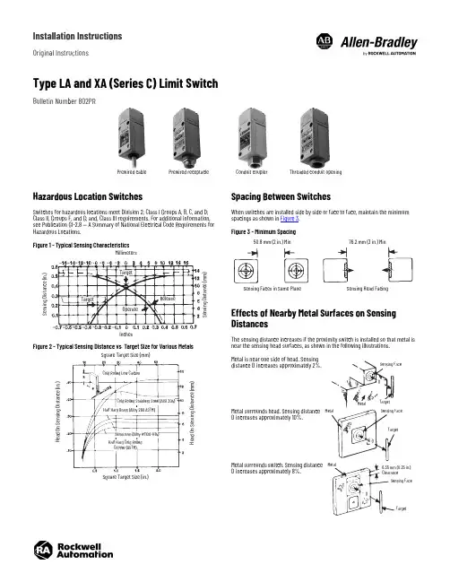
Installation InstructionsOriginal InstructionsType LA and XA (Series C) Limit SwitchBulletin Number 802PRHazardous Location SwitchesSwitches for hazardous locations meet Division 2; Class I Groups A, B, C, and D; Class II, Groups F, and G; and, Class III requirements. For additional information, see Publication GI-2.8 — A Summary of National Electrical Code Requirements for Hazardous Locations.Figure 1 - Typical Sensing CharacteristicsFigure 2 - Typical Sensing Distance vs. Target Size for Various MetalsSpacing Between SwitchesWhen switches are installed side by side or face to face, maintain the minimum spacings as shown in Figure 3.Figure 3 - Minimum SpacingEffects of Nearby Metal Surfaces on Sensing DistancesThe sensing distance increases if the proximity switch is installed so that metal is near the sensing head surfaces, as shown in the following illustrations.Metal is near one side of head. Sensing distance D increases approximately 2%.Metal surrounds head. Sensing distance D increases approximately 10%.Metal surrounds switch. Sensing distance D increases approximately 8%.Prewired cable Prewired receptacle Conduit coupler Threaded conduit openingMillimeters InchesS e n s i n g D i s t a n c e (i n .)S e n s i n g D i s t a n c e (m m )TargetTargetReleaseOperateSquare Target Size (mm)H e a d O n S e n s i n g D i s t a n c e (i n .)H e a d O n S e n s i n g D i s t a n c e (m m )Cold Rolled Low CarbonHalf Hard Brass (Alloy 260 ASTM)Aluminum (Alloy #1100-H14)Square Target Size (in.)Cold Rolled Stainless Steel (AISI 304)Half Hard Cold Rolled Copper (ASTM)50.8 mm (2 in.) Min76.2 mm (3 in.) MinSensing Faces in Same Plane Sensing Head FacingSensing FaceMetalTarget DSensing FaceMetalTargetDSensing FaceMetalTargetD6.35 mm (0.25 in.) Clearance2Rockwell Automation Publication 802PR-IN002B-EN-P - July 2021Type LA and XA (Series C) Limit Switch Installation InstructionsWiringConnect the proximity switch and load as shown in Figure 4 using 0.75…2.5 mm 2 (18…14 AWG) wire. The light-emitting diode (LED) of the switch is on when the load is energized.Figure 4 - Typical Connection Wiring DiagramGroundingThe 802PR limit switch does not require a ground connection. The load side of the 110/120V AC source can be grounded as shown in Figure 5.Shortcut Circuit ProtectionWe recommend using a fast acting Type KAW10 or KAX10 fuse in the circuit to provide short circuit protection for the switch.Series Connected SwitchesNormally Open Fixed OutputDo not connect two or more switches in a series. Doing so can result in erratic operation.Programmable Normally Open (N.O.)/Normally Closed (N.C.) OutputTwo switches can be connected in series with a load. For proper operation, the operating load voltage must be less than or equal to the minimum supply voltage less the sum of the on-state voltage drops across the series connected proximity switches. The load energizes when the output LEDs of both proximity switches are on.Figure 5 - Connection DiagramSpecificationsProgrammable Output SelectionThe programmable N.O./N.C. proximity switch is factory preset in either thenormally open or normally closed output mode. To change the switch output mode:1.Remove the lower legend plate on the front of the switch.2. A line on the recessed rocker indicates the output mode of the switch. Tochange the output, depress the recessed rocker of the switch with a pointed tool.3.Replace the lower legend plate.ATTENTION: If a hazardous condition can result fromunintended energization of this device, access to the sensing area must be guarded.To guard against the load remaining energized when the switch is in an open condition, the minimum load release current must be greater than the maximum leakage current of the proximity switch.L 1L 2Description Output ModeFixed N.O.Programmable N.O./N.C.Operating voltage range102…132V, 50/60 Hz60…132V, 50/60 HzLoad current Max continuous: 1 A to 40 °C (104 °F)linearly derated to 0.5 A at 75 °C (167 °F)Max inrush: 10 A, 1 second maxMin: 0.025 A Max leakage current (load off)0.0065 A0.0035 AMax voltage drop (load on)7.5VOperating temperature range-25…+75 °C (-13…+167 °F)Max operate time 25 ms 25 ms Max release time 35 ms25 ms Delay on power-up targetpresent20 ms, typical (no output occurs with target absent)Sensing distance Steel: 13.33 mm (0.525 in.) +10% -5% (Figure 1 on page 1)Nonferrous metals: 6.35 mm (0.25 in.) typicalHysteresis(operate — release differential) 1.9 mm (0.075 in.) maxSensing distance drift withtemperature ±5%0…75°C (32…167°F)±10%-25…+75°C (-13…167°F)±5%15…50°C (59…122°F)±10%-25…+75°C (-13…+167°F)Max sensing distance drift withvoltage ±0.5% 102 (132V)±1% 90...132V ±3% 60 (132V)Repeat accuracy (10 successive operations)0.03 mm (0.001 in.) max deviation at constant temperatureand supply voltageOperating speed (operations per minute)(1)(1)Based on max operate and release time10001200ATTENTION: Do not connect two or more 802PR limit switches in parallel. Doing so can result in erratic operation.Do not use a tool with a point that can break and jam the switch.L 1L 2Rockwell Automation Publication 802PR-IN002B-EN-P - July 20213Type LA and XA (Series C) Limit Switch Installation InstructionsFigure 6 - View of Rocker SwitchTo return the output mode to its original setting, simply reverse the previous procedure. The output LED is on when the switch output is conducting.Hard Wired ContactsA surge suppressor must be connected in parallel with the load when hard wired contacts are connected in parallel with the 802PR limit switch. Surge suppression is not required when hard wired contacts are connected in series with the load. For recommended surge suppressors for various devices, see publication PROX-TD001.Conduit Coupled SwitchesThreaded conduit opening bases are suitable for use with flexible conduit. Conduit coupler bases are suitable for use with both flexible conduit and rigid conduit. Both bases connect to 12.7 mm (0.5 in.)-14 NPT threaded conduit. Switches with catalog numbers that contain a ‘S6’ suffix are suitable for connection to ISO 20-1.5 threaded conduit.Prewired Cable SwitchesThis type of switch includes a prewired cable for connection directly into a junction box. The cable is a two-conductor, oil-resistant thermoplastic (STO).Prewired Receptacle SwitchesThis type of switch includes a prewired receptacle suitable for use with theconnector-cable assemblies that are listed inTable 1. Figure 7 indicates which twopins of the receptacle are wired internally to terminals 1 and 2. The third pin is not used.Figure 7 - End View of Prewired ReceptacleTroubleshooting GuideThe following guide provides basic troubleshooting information for installation and use of the proximity switch. If a problem occurs, attempt to determine the possible cause, as listed, and apply the suggested solution.Hard wired contacts that are operating in series or parallel with the Bulletin 802PR Type LA or XA limit switch cause a delay ofapproximately 200 ms. This power-up delay reduces the maximum number of operations per minute and can result in a momentary de-energization of the load.Table 1 - Connector Cable (Supplied by User)ManufacturerConnector Cable Part Numbers0.9 m (3 ft) cable1.8 m (6 ft) cable3.7 m (12 ft) cableStandard Color Code (green, black, white)Brad Harrison409014090240903Joy X8984-38984-48984-5CAM-LOK E2057-624E2057-625E2057-626Automotive Color Code (green, red, red)Brad Harrison409584095940960Joy X8984-13X8984-14X8984-15CAM-LOKE2057-824E2057-825E2057-826Normally closed modeNormally open modeDepressed recessed rocker near indication line to change output modeShort Pin -Connects to Terminal 1Short Pin -Connects to Terminal 2The switch can continue to operate even if the LED is damaged (will not light).SymptomOutput LED (1)(1)Programmable N.O./N.C. switches have two LEDs. The power LED is ON when power is applied.Possible CauseSolution N.O.N.C.Load does not energizeOFF OFF Power supply is off.Apply power.OFF ON Incorrect voltageapplied.Apply the correct voltage.OFF OFF Broken wires or loose connections.Repair wiring or tighten loose connections.OFF On Improper wiring.Recheck connectiondiagrams. Rewire accordingly.OFF —The target is too small or out of sensing range.Increase the target size or move target or switch withinsensing range.—OFFA target or metal object is within sensing range.Remove target or metal object. See Effects of Nearby Metal Surfaces on Sensing Distances on page 1.OFF OFF Two or more proximity switches are placed too close together.Move the sensing faces of the switches apart. See SpacingBetween Switches on page 1.ON ON Load device is faulty or incorrect.Replace the load or size loadcorrectly.Load does not de-energizeON—A target or metal object is within sensing range.Remove target or metal object. See Effects of Nearby Metal Surfaces on Sensing Distances on page 1.—ON The target is too small or out of sensing range.Increase the target size or move target or switch withinsensing range.ON ON Two or more proximity switches are placed too close together.Move the sensing faces of the switches apart. See SpacingBetween Switches on page 1.ONOFFImproper wiring.Recheck connection diagrams. Rewire accordingly.OFFOFF Load device is faulty or incorrect.Replace the load or size loadcorrectly.Load energizesand de-energizes intermittentlyON and OFF intermittently Broken wires or loose connections. Repair wiring or tighten loose connections.The target fluctuatesin and out of sensingrange and hysteresiszone.Stabilize the target within the sensing range. See Hysteresis in Specifications on page 2.Two or more proximity switches are placed too close together.Move the sensing faces of the switches apart. See Spacing Between Switches on page 1.Publication 802PR-IN002B-EN-P - July 2021 | Supersedes Publication 802PR-IN002A-EN-P - July 2013Copyright © 2021 Rockwell Automation, Inc. All rights reserved. Printed in the U.S.A.Rockwell Otomasyon Ticaret A.Ş. Kar Plaza İş Merkezi E Blok Kat:6 34752, İçerenköy, İstanbul, Tel: +90 (216) 5698400 EEE Yönetmeliğine UygundurAllen-Bradley, expanding human possibility, and Rockwell Automation are trademarks of Rockwell Automation, Inc.Trademarks not belonging to Rockwell Automation are property of their respective companies.Your comments help us serve your documentation needs better. If you have any suggestions on how to improve our content, complete the form at rok.auto/docfeedback .For technical support, visitrok.auto/support .77050-001-01 Ver 06Waste Electrical and Electronic Equipment (WEEE)Rockwell Automation maintains current product environmental compliance information on its website at rok.auto/pec .At the end of life, this equipment should be collected separately from any unsorted municipal waste.Figure 8 - Mounting Dimensions (mm [in.])41(1.61)26(1.02)109(4.29)6 (0.24)Diagonal Holes Front Mounting DIN (30x60)US (1.18x2.36)6 (0.24)41(1.61)42(1.65)117(4.61)12.7 (0.5)-14 NPT Inside Thread (1)(1) Also available with ISO 20-1.5 threads.(2) Type LA only.15(0.6)Threaded Conduit OpeningConduit Coupler60(2.36)30(1.18)Front Mounting Hole PatternFront View2 Holes for #10 or MS Screws60(2.36)30(1.18)Rear Mounting Hole PatternFront View (2)2 #10-32 Tapped Holes 9.5 (0.37) deep15(0.59)16(0.63)25.4 (1) Hub 12.7 (0.5)-14NPT Inside Threads (1)Prewired CablePrewired Receptacle10 (0.39) diagonal 1.5 mm 2 (16 AWG)2 Conductor STO Cables22(0.87)21.8 (0.86)-16 NPT Outside Threads。
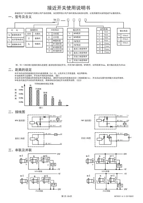
接近开关使用说明书感谢您对广东东崎电气有限公司产品的信赖,当您使用我公司产品时请务必参阅本说明,以免因操作失误而造成不必要的损失。
例:TKI-12N4C表示直插式插头连接型,直流电感式接近开关,外形为M12圆柱型,NPN常开,动作距离为4mm,最大输出电流为200mA.二、距离的设定※开关的动作距离请设定在80%检测距离(Sn)内,以免开关工作受温度、电压等影响。
※当检测其它金属时,开关有不同的动作距离。
(图1)※当开关用作测量动作频率或其它高速场合,请将开关的动作距离设定在1/2检测距离(Sn),开关在此位置可获得最大的动作频率。
※电容式接近开关的动作距离设定,请参阅电容式接近开关的使用说明。
(见五)不锈钢铬镍铜铝二、接线图PNP(直流型)三、串联及并联NPN(直流型)直流二线型检测距离交流二线型(图1)电源电源交流串联交流并联若电源电压为220V,且串联数在3个以内,可使用上图的接法,否则请按下图方法通过继电器进行串联。
并联的开关A和B,若检测体接近开关A,开关A动作,负载电流流过开关A,开关A(B)两端电压降为10V,若此时检测体再接近开关B,因开关两端的电压为10V,开关B会因电压不足而不动作,只有当关闭开关A,使A(B)两端的电压升高至使用电压,开关B才动作,开关A关闭与开关B动作的时间间隔约为10mS,因而当需要多个接近开关并联时应注意开关相互之间的影响,一般请按下图通过继电器进行并联。
电源AC 电源※直流电源必须使用绝缘变压器,请勿使用自耦变压器;※电力线、动力线通过开关引线附近时,为防止开关误动作和损坏,请使用金属配管线。
四、注意事项※交流型开关,若电源电压为110V时,串联必须经过继电器使用;※交流型开关必须经过负载接电源,若直接将开关接电源会损坏开关。
电源AC 电源×错误接法√正确接法※接近开关的引线长度请在200米以下,以免电压降过大。
五、电容式接近开关的使用说明※电容式接近开关不仅能检测金属,而且能检测塑料、玻璃、水、油等物质,因各种检测体的导电率和介电常数、吸水率、体积的不同 故相应检测距离也不同,对于接地的金属可获得最大的检测距离。
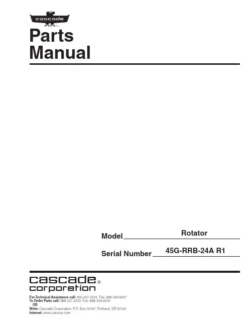
Parts Manual cFor Technical Assistance call: 800-227-2233, Fax: 888-329-8207 To Order Parts call: 888-227-2233, Fax: 888-329-0234Rotator45G-RRB-24A R1ModelSerial Number cascadecorporationSafety DecalsG RotatorREF QTY PART NO.DESCRIPTION 11679150No Step DecalPublicationsG Rotator6073002Installation Instructions672714Operator Guide6073955Service Manual679929Tool Catalog673964Literature Index Order FormRotator Group45GREF QTY PART NO.DESCRIPTION6055356Rotator Group116051999Baseplate216055313Faceplate31775434Bearing Assembly417401Grease Fitting57212305Capscrew, M12 x 3569206174Capscrew, M12 x 45713683822Lockwasher, M1281368073Drive Group u94763021Capscrew, M12 x 30 1016769572Capscrew, M12 x 35 1116678991Lockwasher, M121216605Plug1316036248Seal1416036287Cover Plate153767961Capscrew, M8 x 161617406Grease Fitting171601377Fitting, 8-8 n181605761Fitting, 8-8 n191601250Fitting, 8-8 nu See Drive Group page for parts breakdown.n Included in Fitting Group 212367.Reference: Common Parts 6052002, Fastener Kit 6059211.REF QTY PART NO.DESCRIPTION181670575Gasket191206406Drive Motor – 2.2 c.i.w 2013014870Seal2116033892Bearing s 221675609Worm Gear 231670581Bearing 2417214Snap Ring 251643423O-Ring 261775552Cover 271783609Seal281783608Capscrew, M12 x 16294200882Capscrew, M8 x 20301644010Relief Fitting3144468Capscrew, 3/8 NC x .75 GR8321656300Gear Box Lube – 48 oz.331668184Sealant670578Shim Service Kit (items 4-6,11,25,33)206397Motor Kit (items 11,14,18,19,33)w See Drive Motor page for parts breakdown.s For service replacement use Bearing 670580.REF QTY PART NO.DESCRIPTION368073Drive Group with 2.2 c.i. Motor 16769570Capscrew, M12 x 2521676855Cover 31604510Fitting, 64q 670574Shim – .010" (brown)5q 671757Shim – .015" (pink)6q 671758Shim – .020" (yellow)72670579Bearing 81670582Key 91670506Pinion 101775551Housing 111686465Gasket 121675608Worm 131775553Adapter 1422705O-Ring151670549Check Valve v 1646444Lockwasher174607059Capscrew, 5/16 NC x 1.75 GR8q Quantity as required.v See Check Valve page for parts breakdown.Reference: Common Parts 795490, SKN-5527.Drive Grouponly. Due to cost, if others parts need replacement, the complete drive motor should be replaced.s See Nameplate under valve for correct part number of Gerotor Set and Flange.q Compatible with water glycol based hydraulic fluids.Fork Bar Group45GREF QTY PART NO.DESCRIPTION6055351Fork Bar Group 116055353Upper Bar 216055352Lower Bar314769574Capscrew, M16 x 35414678992Lockwasher, M16526052240Keeper64680084Capscrew, M12 x 2574683822Lockwasher, M12RR0444.epsFork Group45GREF QTY PART NO.DESCRIPTION6055345Fork Assembly 116055341Fork 217000209Knob u 317000194Pin u417000210Coiled Spring Pin u 51700196Spring uu Included in Pin Kit 7000031.Reference:S-22588.Bolt-On Mounting GroupClass II, 0°REF QTY PART NO.DESCRIPTION6051543Mounting Group 11670523Upper Hook – LH 21670524Upper Hook – RH 312766154Capscrew, M16 x 40412217637Washer, M1652675968Lower Hook64765612Capscrew, M16 x 10074781534Nut, M1682781400Spacer91669344Stop Block Kit 101680683Center Spacer112767810Capscrew, M12 x 25P A R T S O R D E R I N G L O GP U R C H A S E S E R I A L R E F C A S C A D E C U S T O M E R D A T EO R D E R N U M B E RP A G E N O .Q T Y P A R T N O .P A R T N O .D E S C R I P T I O N P R I C EcDo you have questions you need answered right now? Call your nearest Cascade Parts Department.Visit us online at Cascade Corporation 2501 Sheridan Avenue Springfield, OH 45505Tel: 888-CASCADE (227-2233)FAX: 888-329-0234Sales RussiaEMCG Material Handling Equipment MoscowTel: 095-795-2400FAX: 095-795-2475Email:****************Sunstream Industries Pte Ltd.No. 3 Tuas Link 12263SingaporeTel: 65-6863-3488FAX: 65-6863-1368Cascade-XiamenNo. 668 Yangguang Rd. Xinyang Industrial Zone Haicang, Xiamen City Fujian Province P .R. China 361026Tel: 86-592-651-2500FAX: 86-592-651-2571Cascade New Zealand 15 Ra Ora DriveEast Tamaki, Auckland New ZealandTel: 64-9-273-9136FAX: 64-9-273-9137Cascade Australia 1445 Ipswich Road Rocklea, QLD 4107AustraliaTel: 1-800-227-223FAX: 617-3373-7333Cascade Korea121B 9L Namdong Ind.Complex, 691-8 Gojan-Dong Namdong-KuInchon, 405-310 Korea Tel: 82-32-821-2051FAX: 82-32-821-2055Cascade Japan Ltd.5-5-41, Torikai Kami Settsu, Osaka Japan, 566Tel: 81-726-53-3490FAX: 81-726-53-3497Cascade (Africa) Pty. Ltd.PO Box 625, Isando 160060A Steel RoadSparton, Kempton Park South AfricaTel: 27-11-975-9240FAX: 27-11-394-1147Sales Poland Targowa 35/6103-728 Warszawa Tel: 022-619 00 49FAX: 022-619 00 49Mobile Phone: 0501-27 29 55Sales Switzerland Fahrzeugbedarf 8810, Horgen Switzerland Tel: 01-7279797FAX: 01-7279798Sales Portugal FAG Santos LdaRua do MercadoLte 6, Loja 2-Tires 2785-630S. Domingos De Rana PortugalTel: 214-448-083FAX: 214-458-098Cascade Roncari S.R.L.Via Dell’Artigianato 137050 Vago di Lavagno (VR) ItalyTel: 39-045-8989111FAX: 39-0458989160Cascade Hispania S.A.Carrer 5, Sector C Zona Franca DuaneraPoligono de la Zona Franca 08040 Barcelona, Spain Tel: 93-264-07-30FAX: 93-264-07-31Cascade France S.A.R.L. MHP1D Rue De Charaintru BP 18, 91360 Epinay-Sur-Orge FranceTel: 01-6454-7500FAX: 01-6454-7501Cascade Scandinavia AB Hammarvägen 10PO Box 124S-56723 Vaggeryd SwedenTel: 039-336950FAX: 039-336959Sales ScotlandMacade Systems Ltd.18 Melford Road Righead Ind. Estate Bellshill ML4 3LR ScotlandTel: 01698-845777FAX: 01698-845888Cascade (UK) Ltd.Unit 4, 12 O’Clock Court Attercliffe Road Sheffield, S4 7WW EnglandTel: 0870-850-8756FAX: 0870-850-8757Cascade N.V.Benelux Sales and Service Damsluisweg 56PO Box 30091300 El Almere The Netherlands Tel: 036-5492950FAX: 036-5492974Cascade Finland A. Petreliuksenkatu 301370 Vantaa FinlandTel: 09-8361925FAX: 09-8361935Cascade GmbHDahlener Strasse 57041239 Mönchengladbach GermanyTel: 02166-68230FAX: 02166-682323Cascade Canada Inc.5570 Timberlea Blvd.Mississauga, Ontario Canada L4W-4M6Tel: 905-629-7777FAX: 905-629-7785。

■限位开关的概念限位开关,指为保护内置微动开关免受外力、水、油、气体和尘埃等的损害,而组装在外壳内的开关,尤其适用于对机械强度和环境适应性有特殊要求的地方。
形状大致分为横向型、竖向型和复合型。
下图表示典型的竖向型限位开关的构造。
限位开关大致上是由五个构成要素组成的。
■内置微动开关驱动机构对于限位开关来说,微动开关的驱动机构是与密封性能和动作特性直接相关的重要部分。
其构造分为三类,如下表所示。
(1)活塞型根据密封方法不同,有表中的A型和B型2个种类。
A型是用O型环或薄膜密封的,由于密封橡胶没有外露,在抵制工作机械的切割碎屑方面功能较强大,但其反面影响是,有可能会将砂子、切割粉末等压入活塞的滑动面。
B型虽然不会把砂子、切割粉末等压入,且密封性能优于A型,但由于炽热的切割碎屑飞溅过来,有可能会损坏橡胶帽。
因此,要根据使用场所的不同选用A型或B型。
而柱塞型仍然通过柱塞的往复运动压缩或吸进空气。
为此,如果长时间将柱塞压入,限位开关内的压缩空气逸失,内部压力将与大气压相同,即使急于让柱塞复位,柱塞却有迟缓复位的倾向。
为了避免发生这种故障,设计时,根据柱塞的压入将空气的压缩量控制在限位开关内部全部空气量的20%以内。
另外,为了延长微动开关的寿命,在这一构造内部设置了一个OT吸收机构,该OT吸收机构采用OT吸收弹簧,用以吸收残余的柱塞的行程。
该机构相对于柱塞的运动,在中途停止按压微动开关辅助柱塞的行程。
(2)铰链摆杆型在摆杆端部(滚珠),柱塞的行程量根据摆杆的比例扩大,因此,一般不使用OT吸收机构。
(3)旋转摆杆型举一个典型的示例,来示例WL的构造,但除此之外,还有两个类型:将复位柱塞的功能赋予柱塞的类型;通过线圈弹簧获取复位力、用凸轮带动辅助柱塞的类型。
■开关的构成材料开关的主要部分是由下列材料构成的限位开关用语说明限位开关:为保护小型开关不受外力、水、油、尘埃等的侵害而将其装入金属外壳或者塑料外壳中的开关。

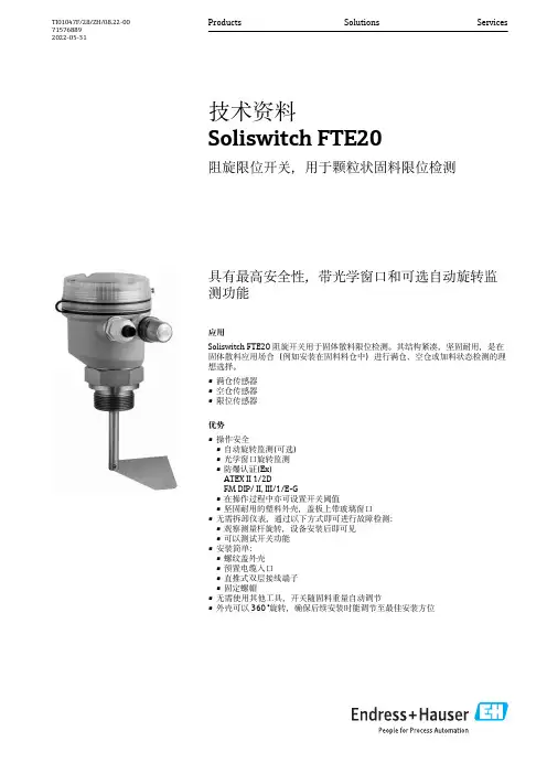
具有最高安全性,带光学窗口和可选自动旋转监测功能应用Soliswitch FTE20阻旋开关用于固体散料限位检测。
其结构紧凑,坚固耐用,是在固体散料应用场合(例如安装在固料料仓中)进行满仓、空仓或加料状态检测的理想选择。
•满仓传感器•空仓传感器•限位传感器优势•操作安全•自动旋转监测(可选)•光学窗口旋转监测•防爆认证(Ex)ATEX II 1/2DFM DIP/ II, III/1/E-G•在操作过程中亦可设置开关阈值•坚固耐用的塑料外壳,盖板上带玻璃窗口•无需拆卸仪表,通过以下方式即可进行故障检测:•观察测量杆旋转,设备安装后即可见•可以测试开关功能•安装简单:•螺纹盖外壳•预置电缆入口•直推式双层接线端子•固定螺帽•无需使用其他工具,开关随固料重量自动调节•外壳可以360 °旋转,确保后续安装时能调节至最佳安装方位Products Solutions Services技术资料Soliswitch FTE20阻旋限位开关,用于颗粒状固料限位检测TI01047F/28/ZH/08.22-00715768892022-05-31Soliswitch FTE202Endress+Hauser功能与系统设计测量原理阻旋开关主要用于固料料仓中的满仓或加料状态检测。
用作加料开关时,阻旋开关通常安装在料仓底部,或倾斜安装在料仓锥体部分。
用作满仓开关时,阻旋开关安装在仓顶。
同步电机控制减速齿轮,带动传动轴和叶片旋转。
被散料覆盖时,叶片停止运动,外壳内的旋转电机从休止位置切换至开关位置,导致两个开关触点动作;一个触点用于外部料位标识,另一个触点用于切断电机电源。
料位下降至低于叶片位置后,电机返回休止位置。
两个开关触点再次切换至休止位置,叶片继续旋转。
滑动离合器吸收叶片上与旋转方向相同或相反的间歇性载荷。
盖板关闭时,可以从外部观察传动轴的旋转运动。
可选自动旋转监测功能用于驱动单元的堵塞或故障检测。
测量系统整套阻旋限位开关包括带同步电机和滑动离合器的传动轴(可选带延长缆(可截短)的设备型号),以及单极可切换触点。
8185377
1EX 标记
2适用文件
3认证的产品
4安全
4.1安全注意事项
–本装置在规定的运行条件下可应用于爆炸性气体环境 2 区以及爆炸性粉尘
环境 22 区。
–只能在潜在爆炸性区域以外执行所有作业。
–必须确保防护等级 IP65。
–请在原装状态下使用本装置,切勿擅自进行任何改动。
–关于产品的一切工作仅允许由具备资质的专业人员进行,这些专业人员对工
作进行评估并识别出危险。
–仅使用适合该防爆等级的附件 è /catalogue。
4.2按规定使用
该设备感测、传输和显示过程设备中角行程驱动器的位置。
4.3标记 X:特殊条件
–在电缆接头前使用额外的电缆应力消除件。
–静电放电可造成危险。
–环境温度 –20 °C £ Ta £ +80 °C。
–该设备只能在污染等级不超过 2(依据 IEC 60664-1 定义)的环境中使用。
5功能
限位开关盒用于感测驱动器的终端位置并以电子信号和光学指示进行反馈。
6调试
7维护
–设备无需维护。
–无法进行修理。
8技术参数。

限位开关行程开关安全操作及保养规程限位开关行程开关是一种常见的机电装置,在各种工业领域中广泛应用。
它能够控制和监测机械设备的运行状态,以确保设备的安全性和稳定性。
为了确保限位开关行程开关的正常运行和延长使用寿命,以下是一些安全操作和保养规程。
安全操作规程1. 原则任何人员在操作限位开关行程开关时,必须遵循相关的安全操作规程,严格按照说明书进行操作,并遵守现场的安全作业规定。
对于那些没有经过相应培训的人员,必须禁止进行操作。
2. 操作步骤在限位开关行程开关的操作过程中,必须按照以下步骤进行操作:•仔细阅读说明书,了解设备的结构和原理。
•对设备进行初步检查,确保设备处于工作状态。
•确定要控制的机械部件,对其进行定位,并将行程开关安装在合适位置。
•检查电线连接,确认无错误连接。
•慢慢旋转行程开关的旋钮,直至达到所需的位置,设定最大和最小限位值。
•连接电源,进行实际测试。
•对测试结果进行记录,并进行调整和修正。
在操作的过程中,必须保证各项工作完成完整,操作无误。
3. 安全措施在限位开关行程开关操作的过程中,必须要保证自身安全,同时也要对设备和周围环境进行保护。
需遵循以下安全措施:•严格按照说明书操作,避免误操作和危险操作。
•穿戴符合要求的劳保用品,如安全鞋、安全帽、安全手套等。
•避免碰撞行程开关,以防止设备受损或人员意外受伤。
•保持设备周围的通道畅通,避免杂物堆放,以防行程开关受到干扰或短路。
•定期对设备的零部件、电线、连接器和端子进行检查,确保其完好无损,避免出现安全隐患。
保养规程限位开关行程开关的保养是延长其使用寿命的重要措施,遵循以下保养规程能够保证其正常运行,并最大限度地减少故障。
1. 定期检查对于长期运转的限位开关行程开关,应定期进行检查和维护,发现故障及时解决。
以下是一些定期检查内容:•检查设备运行是否正常,是否能够准确切换。
•检查电源电压,确认是否在规定范围内,以及电源接线是否松动等。
•检查双向限位开关开关量程,以及触点接触是否良好,需要进行必要的清扫或更换。
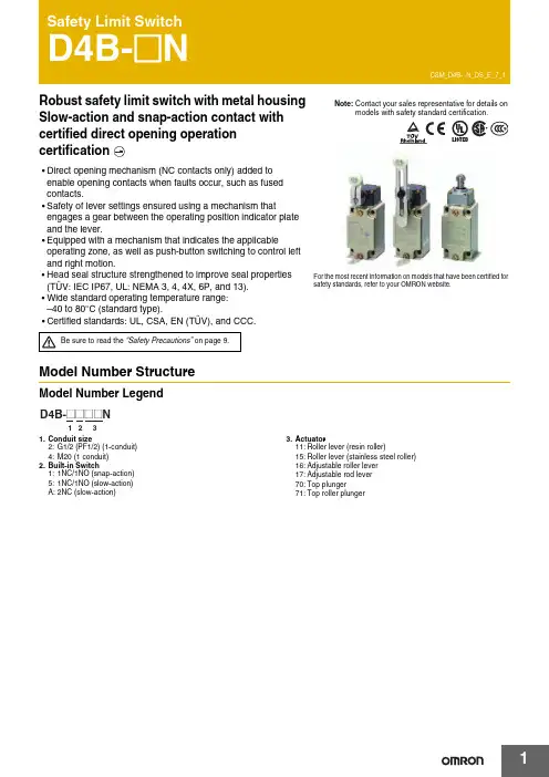
Robust safety limit switch with metal housing Slow-action and snap-action contact with certified direct opening operation•Direct opening mechanism (NC contacts only) added to enable opening contacts when faults occur, such as fused contacts.•Safety of lever settings ensured using a mechanism thatengages a gear between the operating position indicator plate and the lever.•Equipped with a mechanism that indicates the applicableoperating zone, as well as push-button switching to control left and right motion.•Head seal structure strengthened to improve seal properties(TÜV: IEC IP67, UL: NEMA 3, 4, 4X, 6P, and 13).•Wide standard operating temperature range: –40 to 80°C (standard type).•Certified standards: UL, CSA, EN (TÜV), and CCC.Model Number StructureModel Number Legend 1.Conduit size2:G1/2 (PF1/2) (1-conduit)4:M20 (1 conduit)2.Built-in Switch1:1NC/1NO (snap-action)5:1NC/1NO (slow-action) A:2NC (slow-action)3.Actuator11:Roller lever (resin roller)15:Roller lever (stainless steel roller)16:Adjustable roller lever 17:Adjustable rod lever 70:Top plunger71:Top roller plungerFor the most recent information on models that have been certified for safety standards, refer to your OMRON website.Be sure to read the “Safety Precautions” on page 9.Ordering InformationSet Model NumbersConsult with your OMRON representative when ordering any models that are not listed in this table. Safety Limit Switches (with Direct Opening Mechanism)General-purpose Limit SwitchesNote:Consult your OMRON representative for products.SpecificationsStandards and EC DirectivesConforms to the following EC Directives:•Machinery Directive •Low Voltage Directive •EN50041•EN60204-1•EN1088Certified StandardsSnap-action ModelsSlow-action ModelsCertified Standard RatingsTÜV (EN60947-5-1), CCC (GB14048.5)Note:As protection against short-circuiting, use either a gI -type or gG -type 10 A fuse that conforms to IEC60269.UL/CSA: (UL508, CSA C22.2 No. 14)A600ItemUtilization category AC-15Rated operating current (I e ) 2 A Rated operating voltage (U e )400 VRated voltage Carry currentCurrent (A)Volt-amperes (VA)MakeBreakMakeBreak120 VAC 240 VAC 480 VAC 600 VAC10 A 60 30 15 126 3 1.5 1.27,200 720RatingsNote:1.The above values are continuous currents.2.Inductive loads have a power factor of 0.4 or higher (AC) or a time constant of 7 ms or lower (DC).mp loads have a inrush current of 10 times the normal current.4.Motor loads have a inrush current of 6 times the normal current.CharacteristicsNote:1.The above values are initial values.2.The above values may vary depending on the model. Consult your OMRON sales representative for details.*1.The degree of protection is tested using the method specified by the standard (EN60947-5-1). Confirm that sealing properties are sufficient forthe operating conditions and environment beforehand.*2.The durability is for an ambient temperature of 5 to 35°C and ambient humidity of 40% to 70%. For further conditions, consult your OMRONsales representative.*3.The above values may vary depending on switching frequency, environmental condition, and relativity level, consult your OMRON salesrepresentative.Rated voltage (V)Non-inductive load (A)Inductive load (A)Resistive load Lamp loadInductive loadMotor loadNCNONCNONCNONCNO125 VAC 250400101010321.5 1.510.810103531.5 2.51.50.88 VDC 1430125250101060.80.46640.20.13330.20.1101060.80.46640.20.1Inrush current30 A max.Degree of protection *1IP67 (EN60947-5-1)Durability *2Mechanical 30,000,000 operations min. (snap-action)10,000,000 operations min. (slow-action)Electrical500,000 operations min. (10 A resistive load at 250 VAC)Operating speed 1 mm/s to 0.5 m/s Operating frequency Mechanical 120 operations/minute Electrical 30 operations/minute Contact resistance25 m Ω max.Minimum applicable load *3General load 180 mA resistive load at 5 VAC Gold-clad contact 20 mA resistive load at 5 VAC (N-level reference value)Rated insulation voltage (U i )600 V (EN60947-5-1)Rated frequency50/60 HzProtection against electric shock Class I (with ground terminal)Pollution degree (operating environment)3 (EN60947-5-1)Impulse withstand voltage (EN60947-5-1)Between terminals of same polarity2.5 kV (snap-action)/4 kV (slow-action)Between terminals of different polarity4 kV (slow-action)Between eachterminal and ground4 kVInsulation resistance 100 M Ω min. (at 500 VDC) between terminals of the same polarity and between each terminal and non-current-carrying part Contact gap 2 × 2 mm min. (slow-action)2 × 0.5 mm min. (snap-action)Vibration resistance Malfunction 10 to 55 Hz, 0.75 mm single amplitude Shock resistanceDestruction 1,000 m/s 2 min.Malfunction300 m/s 2 min.Conditional short-circuit current100 A (EN60947-5-1)Conventional enclosed thermal current (I the )20 A (EN60947-5-1)Ambient operating temperature –40 to 80°C (with no icing) Ambient operating humidity 95% max.WeightApprox. 250 gEngineering DataElectrical Durability (Snap-action)(Ambient temperature: 5 to 30°C, ambient humidity: 40 to 70%)Structure and NomenclatureStructure250 V AC 125 V AC1,0001,000500500300300100100505030301010480 V AC 250 V AC500 V AC(cos φ = 1)(cos φ = 0.4)O p e r a t i o n s (x 104)O p e r a t i o n s (x 104)S w itching c u rrent (A)S w itching c u rrent (A)Operating fre qu encies: 30 times/min., cos φ = 1Operating fre qu encies: 30 times/min., cos φ = 0.4selection of operation on only oneDirect Opening Mechanism1NO/1NC Contact (Snap-action)1NC/1NO Contact (Slow-action)2NC Contact (Slow-action)Contact FormNote:Terminal numbers are according to EN50013; contact symbols are according to IEC60947-5-1.AMo v a b le contactPl Safety camFixed contact (N C)le contact Safety cam directly p mo b lled apart.Dimensions and Operating Characteristics(Unit: mm)Note:Omitted dimensions are the same as those for the Roller Lever Type ModelsD4B-2@@@N have a G1/2 conduit opening. D4B-4@@@N have a M20 conduit opening.SwitchesNote:Unless otherwise specified, a tolerance of 0.4 mm applies to all dimensions.*1.The lever can be set to any desired position by turning the operating position indicator.*2.In terms of construction, the Switch is a General-purpose Limit Switch rather than a Safety Limit Switch.Note:Variation occurs in the simultaneity of contact opening/closing operations of 2NC contacts. Check contact operation.*1.The operating characteristics of these Switches were measured with the roller level set at 31.5 mm.*2.The operating characteristics of these Switches were measured with the rod level set at 140 mm.*3.Only for slow-action models.*4.Only for snap-action models.*5.Reference values.*6.Must be provided to ensure safe operation.Model Operating characteristics D4B-@@11N D4B-@@15N D4B-@@16N *1D4B-@@17N*2Operating force Release force PretravelOvertravelMovement differential Direct opening travel Direct opening force Total travelOF max.RF min.PTPT (2nd) *3 *5OT min.MD max. *4DOT min. *3 *6*4 *6DOF min. *6TT *59.41N1.47N 21°±3°(45°)50°12°35°55°19.61N (75°)9.41N 1.47N 21°±3°(45°)50°12°35°55°19.61N (75°)9.41N 1.47N 21°±3°(45°)50°12°35°55°19.61N (75°)2.12N 0.29N 21°±3°(45°)50°12°35°55°19.61N (75°)131.325 to Adjustable Roller Lever D4B-@@16NAdjustable Rod Lever D4B-@@17NNote:Unless otherwise specified, a tolerance of ±0.4 mm applies to all dimensions. Operating characteristics Model D4B-@@70N D4B-@@71NOperating force Release force PretravelOvertravel Movement differential Direct opening travel Direct opening force Total travel OF max.RF min.PT max.PT (2nd) *1 *3OT min.MD max. *2DOT min. *4DOF min. *4TT *318.63 N1.96 N2 mm(3 mm)5 mm1 mm3.2 mm49.03 N(7 mm)18.63 N1.96 N2 mm(3 mm)5 mm1 mm3.2 mm49.03N(7 mm)Note:Variation occurs in the simultaneity ofcontact opening/closing operations of2NC contacts. Check contactoperation.*1.Only for slow-action models.*2.Only for snap-action models.*3.Reference values.*4.Must be provided to ensure safeoperation.Free position Operating position FP max.OP38 mm35±1 mm51 mm48±1 mmApplication PrecautionSafety PrecautionsBe sure to read the precautions for All Safety Limit Switches in the website at:/.Indication and Meaning for Safe Use•Do not use the Switch submerged in oil or water, or in locations continuously subject to splashes of oil or water. Doing so may result in oil or water entering the Switch interior. (The IP67 degree of protection specification for the Switch refers to water penetration while the Switch is submersed in water for a specified period of time.)•Always attach the cover after completing wiring and before using the Switch. Also, do not turn ON the Switch with the cover open.Doing so may result in electric shock.MountingUse four M5 screws with washers to mount the standard model. Be sure to apply the proper torque to tighten each screw. Mounting Dimensions (M5)•To change the angle of the lever, loosen the Allen-head bolts on the side of the lever.•The operating position indicator plate * has protruding parts which engage with the lever, thus allowing changes to the lever position by 90°.•The back of the operating position indicator plate * has noprotruding parts. If this plate is turned over and attached, any angle within a 360° range can be set. Do not turn over the plate, however, when using the D4B-@N as a switch with a certified direct opening mechanism. For an SUVA- or BIA-certified application, make sure that the lever engages with the operating position indicator plate securely so that the lever will not slip.*The operating position indicator plate: Refer to page 5. Changes in Head Mounting PositionBy removing the screws on the four corners of the head, the head can be reset in any of four directions. Make sure that no foreign materials will penetrate through the head.Changing the Operating Direction Switches with Roller LeversThe operating direction of the lever can be easily changed without using any tools. It can be set toclockwise operation (CW) or counterclockwise (CCW) operation.Use the procedure given at the right to change the operating direction.Head Co OperatingPrecautions for Safe Use Supplementary comments on what to do or avoid doing, to use the product safely.Precautions for Correct Use Supplementary comments on what to do or avoid doing, to prevent failure to operate, or undesirable effect on product performance.Precautions for Safe Use Precautions for Correct UseD4B-@NWiringDo not connect the bare lead wires directly to the terminals but be sure to connect each of them by using an insulation tube and M3.5 round crimp terminals and tighten each terminal screw within the specified torque range.The proper lead wire is 20 to 14 AWG (0.5 to 2.5 mm 2) in size.Make sure that all crimp terminals come into contact with the casing or cover as shown below, otherwise the cover may not be mounted properly or the D4B-@N may malfunction.Conduit Opening•Make sure that each connector is tightened within the specifiedtorque range.The casing may be damaged if the connector is tightened excessively.•Use an OMRON SC-series Connector (sold separately) that is suited to the cable in diameter.Others•The load for the actuator (roller) of the Switch must be imposed on the actuator in the horizontal direction, otherwise the actuator or•@@17N, theSwitch may telegraph. To avoid telegraphing, take the following precautions.1.Set the lever to operate in one direction.2.Modify the rear end of the dog to an angle of 15° to 30° as3.signals.D dia.dz dia.CasingCo v erT erminal scre wCrimp terminalT erminal scre wCasingT erminal scre wCo v erCrimp terminalCorrectCorrectIncorrectIncorrectCrimp terminalCrimp terminalCrimp terminalCorrectIncorrectRead and Understand This CatalogPlease read and understand this catalog before purchasing the products. Please consult your OMRON representative if you have any questions orcomments.WARRANTYOMRON's exclusive warranty is that the products are free from defects in materials and workmanship for a period of one year (or other period if specified) from date of sale by OMRON.OMRON MAKES NO WARRANTY OR REPRESENTATION, EXPRESS OR IMPLIED, REGARDING NON-INFRINGEMENT, MERCHANTABILITY, OR FITNESS FOR PARTICULAR PURPOSE OF THE PRODUCTS. ANY BUYER OR USER ACKNOWLEDGES THAT THE BUYER OR USER ALONE HAS DETERMINED THAT THE PRODUCTS WILL SUITABLY MEET THE REQUIREMENTS OF THEIR INTENDED USE. OMRON DISCLAIMS ALL OTHER WARRANTIES, EXPRESS OR IMPLIED.LIMITATIONS OF LIABILITYOMRON SHALL NOT BE RESPONSIBLE FOR SPECIAL, INDIRECT, OR CONSEQUENTIAL DAMAGES, LOSS OF PROFITS OR COMMERCIAL LOSS IN ANY WAY CONNECTED WITH THE PRODUCTS, WHETHER SUCH CLAIM IS BASED ON CONTRACT, WARRANTY, NEGLIGENCE, OR STRICT LIABILITY.In no event shall the responsibility of OMRON for any act exceed the individual price of the product on which liability is asserted.IN NO EVENT SHALL OMRON BE RESPONSIBLE FOR WARRANTY, REPAIR, OR OTHER CLAIMS REGARDING THE PRODUCTS UNLESSOMRON'S ANALYSIS CONFIRMS THAT THE PRODUCTS WERE PROPERLY HANDLED, STORED, INSTALLED, AND MAINTAINED AND NOTSUBJECT TO CONTAMINATION, ABUSE, MISUSE, OR INAPPROPRIATE MODIFICATION OR REPAIR.SUITABILITY FOR USEOMRON shall not be responsible for conformity with any standards, codes, or regulations that apply to the combination of products in the customer's application or use of the products.At the customer's request, OMRON will provide applicable third party certification documents identifying ratings and limitations of use that apply to the products. This information by itself is not sufficient for a complete determination of the suitability of the products in combination with the end product, machine, system, or other application or use.The following are some examples of applications for which particular attention must be given. This is not intended to be an exhaustive list of all possible uses of the products, nor is it intended to imply that the uses listed may be suitable for the products:∙Outdoor use, uses involving potential chemical contamination or electrical interference, or conditions or uses not described in this catalog.∙Nuclear energy control systems, combustion systems, railroad systems, aviation systems, medical equipment, amusement machines, vehicles, safety equipment, and installations subject to separate industry or government regulations.∙Systems, machines, and equipment that could present a risk to life or property.Please know and observe all prohibitions of use applicable to the products.NEVER USE THE PRODUCTS FOR AN APPLICATION INVOLVING SERIOUS RISK TO LIFE OR PROPERTY WITHOUT ENSURING THAT THE SYSTEM AS A WHOLE HAS BEEN DESIGNED TO ADDRESS THE RISKS, AND THAT THE OMRON PRODUCTS ARE PROPERLY RATED AND INSTALLED FOR THE INTENDED USE WITHIN THE OVERALL EQUIPMENT OR SYSTEM.PROGRAMMABLE PRODUCTSOMRON shall not be responsible for the user's programming of a programmable product, or any consequence thereof.CHANGE IN SPECIFICATIONSProduct specifications and accessories may be changed at any time based on improvements and other reasons.It is our practice to change model numbers when published ratings or features are changed, or when significant construction changes are made.However, some specifications of the products may be changed without any notice. When in doubt, special model numbers may be assigned to fix or establish key specifications for your application on your request. Please consult with your OMRON representative at any time to confirm actualspecifications of purchased products.DIMENSIONS AND WEIGHTSDimensions and weights are nominal and are not to be used for manufacturing purposes, even when tolerances are shown.PERFORMANCE DATAPerformance data given in this catalog is provided as a guide for the user in determining suitability and does not constitute a warranty. It may represent the result of OMRON’s test conditions, and the users must correlate it to actual application requirements. Actual performance is subject to the OMRON Warranty and Limitations of Liability.ERRORS AND OMISSIONSThe information in this document has been carefully checked and is believed to be accurate; however, no responsibility is assumed for clerical,typographical, or proofreading errors, or omissions.2012.10In the interest of product improvement, specifications are subject to change without notice. OMRON CorporationIndustrial Automation Company/(c)Copyright OMRON Corporation 2012 All Right Reserved.。
![基于PLC控制水电站闸门越限防护研究与实现[论文]](https://uimg.taocdn.com/69098a5d3c1ec5da50e2700a.webp)
基于PLC控制的水电站闸门越限防护的研究与实现摘要:为了保证水电站闸门安全可靠的运行,必须对闸门行程进行上下限位。
传统的限位措施是在闸门控制系统中安装相应的机电限位装置,该措施单一但可靠性不足,更不能检测闸门开度。
提出一种闸门越限防护的双重机制:将旋转限位开关及编码器相结合,有效地实现闸门开度检测与行程限制。
关键词:越限防护开度检测中图分类号:tv734 文献标识码:a 文章编号:1007-3973(2013)005-024-031 闸门越限防护必要性水电站卷扬式闸门启闭机运行时,如果闸门上升到顶部极限还在运行,则会引起闸门拉弯变形、钢丝绳拉断以及水坝枢纽受损等重大事故,给水电站造成巨大的损失。
因此,必须对闸门进行上下限位,确保闸门安全准确的停止。
目前,水电站闸门越限防护采用的是机械限位,即在卷扬式启闭机上安装相应的机电限位装置,这种方法虽然简单,但是单一的限位措施可靠性不足。
本文提出了一种闸门越限防护的双重机制:将旋转限位开关及编码器限位相结合,有效地完成闸门开度的实时检测与行程限制。
2 越限防护的机制2.1 基于旋转编码器的越限防护(1)编码器的安装。
由于电机转速较快,而绝对式编码器的量程有限,所以编码器不能直接安装在电机的主轴上。
但是,电机主轴输出的转速在经过减速箱传递到钢丝绳的卷筒时,转速就小很多。
将绝对式编码器安装在卷扬机的卷筒上,使编码器的主轴与卷筒同步转动。
其优点有:1)编码器量程满足要求,编码器能发挥越限防护作用;2)卷筒转速低且转动平稳,可以避免由于高速震动使编码器损坏的事故;3)编码器拆卸方便,容易进行维护养。
(2)工作原理。
编码器的原理:编码器是用来测量角度、位置的传感器,依靠轴杆、齿轮、测量轮的控制,检测线性的位移。
编码器将实际的机械参数值转换成电气信号,这些电气信号经plc处理,形成控制系统所要求的参数。
越限防护原理:编码器与卷筒同轴连接,随着卷筒同步转动,卷筒每转动一定的角度,闸门就提升一段距离,编码器累加一定的脉冲数。
旋转式开关Cam SwitchesMERZ旋转式产品系列MERZ CAM SERIES旋转式开关旋转式开关根据其触点配置,开关中带有1、2或3个(仅111系列)双遮断触点回路。
每个导电路径均由一对结实结构的端子和一个连动机件组成。
透过旋转即可打开,并经由弹簧关闭。
指示装置含有4个不同的切换角度及扭矩。
防误触电击的旋转开关配有带固定的螺钉。
所有端子均可由一般螺丝刀简便固定,漏斗形电缆入口以及类似腔体的设计。
电缆末端的挡块可确保正确的插入深度。
Cam SwitchesCam Switches according to their contact arrangement are fitted with switching chambers with 1, 2 or 3 (series 111 only) double interrupted conduct paths. Each conduct path is arranged of 2 firmly seated terminals and one mobile contact bridge which is guided by a plunger. The contact bridge is positively opened by the cam and closed by a spring. The indexing device is available in different torques and 4 different switching angles. The finger proof Cam Switches are equipped with screws with captive screw heads. All terminals are fitted with screwdriver guiding, funnel-shaped cable entries and in chamber like design. Cable end stops assure the correct insertion depth.规格总览OVERVIEW SPECIFICATIONS参数Specific ations從/from到/to额定工作电流 Ie AC-21ARated operational current Ie AC-21A A16125符合认证 IEC 60947-3, EN 60947-3 ACC. IEC 60947-3, EN 60947-3额定工作电压 UeRated operational voltage Ue额定不间断电流 Ith offenRated uninterrupted current Ithopen额定不间断电流 Ithe 封裝的Rated uninterrupted current Itheencapsulated额定绝缘电压 Ui 绝缘等级 C 符合 VDE 0110Rated insulation voltage UiInsulation group C acc. VDE 0110额定冲击耐受电压 Uimp (III/3)Rated impulse withstand voltage Uimp(III/3)段位自定义马达开关Motor switch for operational switching单相马达开关Single-phase motor马达开关Motor switch主开关Main switch维护开关Maintenance switchV690500A20125A20125V690500kV46kW322 230 V 3~kW5,545 400 V 3~kW5,545 690 V 3~kW2,211 230 V 3~kW318,5 400 V 3~kW437 230 V 3~kW7,545 400 V 3~kW7,545 690 V 3~断开和关合能力使用类别 AC-3MAKING BREAKING CAPACITY UTILISATION CATEGORY AC-3断开和关合能力使用类别 AC-23A/(B)MAKING BREAKING CAPACITY UTILISATION CATEGORY AC-23A/(B)前板安装Front mounting底部安装Base mounting外壳封闭式EnclosureDESIGN FRONT MOUNTING双孔/四孔安装- 1简易旋钮(P25/P25.9无挂锁)ON-OFF指示 面板 / MN 104-756型2/4-hole mounting with frontplate without padlock 型/Type: MN 104 - 756单孔安装- 3中央圆孔(Φ=22,5 / 30,5 mm) 简易旋鈕(P25/P25.9无挂锁)ON-OFF指示面板22,5 / 30,5 mm Central mounting with frontplate without padlock型/Type: MN 104,105,107,111,151,251单孔安装- 1中央圆孔(Φ=16,0 mm)简易旋钮(P25/ P25.9无挂锁)MN 105型16,0 Central mounting without frontplate without padlock 型/Type: MN 105双孔/四孔安装- 3美规带锁旋钮(灰/黑)MN 104,105,111,151,251,451型 2/4-hole mounting with lockout handle for 3 padlocks型/Type: MN 104,105,111,151,251,451单孔安装- 5中央圆孔(Φ=22,5 / 30,5 mm)美规带锁旋 钮(灰/黑)锁孔三方位可选22,5 / 30,5 mm Central mounting with lockout handle for 3 padlocks 型/Type: MN 104,105,111,151,251单孔安装- 2中央圆孔(Φ=22,5 / 30,5 mm)简旋钮(P25/ P25.9无挂锁)MN 104,105,107,111,151,251型22,5 / 30,5 Central mounting without padlock 型/Type: MN 104,105,107,111,151,251双孔/四孔安装- 2單锁孔旋鈕(EVS) / ON-OFF指示面板 MN 104,105,151型2/4-hole mounting with frontplate with lockout handle for 1 or 2 padlock 型/Type: MN 104,105,151单孔安装- 4中央圆孔(Φ=22,5 / 30,5 mm) 單锁孔旋鈕 (EVS) / ON-OFF指示面板22,5 / 30,5 mm Central mounting with front -plate with lockout handle for 1 or 2 padlock 型/Type: MN 104,105,151依设计需求提供 多色搭配Available coloursfor all housing designsDESIGN BASE MOUNTING配电盘/箱体- 1旋钮内置箱体(不外露) 、ON-OFF指示面板 螺丝 /卡扣式安装、MN 104,105型Distribution board mounting 1 with screwand snap-on mounting 型 /Type: MN 104,105底部安装- 1簡易旋鈕(P25/P25.9无挂锁)门板轴心对接 器件组、ON-OFF指示面板Cover coupling 1 with front plate without padlock型 /Typ: MN 104,105,111,151,251,451底部安装- 2简易带锁旋钮(EVS)单锁孔门板轴心对接 器件组MN 104,105,151型Door coupling 2 with lockout handle for 1 or 2 padlocks型/Typ: MN 104,105,151底部安装- 3美规带锁旋钮(灰/黑)、锁孔三方位可选门 板轴心对接器件组Cover coupling 3 with locklout handle for 3 padlocks型 /Typ: MN 104,105,111,151,251,451底部安装- 3美规带锁旋钮(红/黄)、锁孔三方位可选门 板轴心对接器件组MN 104 - 756型Door coupling 3 with locklout handle for 3 padlocks型/Typ: MN 104 - 756底部安装- 1簡易旋鈕(P25/P25.9无挂锁)门板轴心对接 器件组、ON-OFF指示面板Door coupling 1 with front plate without padlock 型/Typ: MN 104 - 756配电盘/箱体- 2旋钮内置箱体(不外露) 、ON-OFF指示面板螺丝 /按扣式安装、MN 104,105型Distribution board mounting 2 with screw and snap-on mounting 型 /Typ: MN 104,105底部安装- 2單锁孔旋鈕(EVS) / 门板轴心对接器件组 ON-OFF指示面板Cover coupling 2 with lockout handle for 1 or 2 padlocks型 /Typ: MN 104,105,151依设计需求提供 多色搭配Available coloursfor all housing designs外壳封闭式壁挂安装DESIGN WALL MOUNTING ENCLOSED壁挂式旋转式开关外壳封闭式设计 旋转式开关类型: 105,111,151,251,451Wall mounting enclosed design,with lockout handle for 3 padlocks 壁挂式旋转式开关外壳封闭式设计 旋转式开关类型: 105,111,151,251,451Wall mounting enclosed design,without padlock 壁挂式旋转式开关外壳封闭式设计旋转式开关类型: 105,111,151Wall mounting enclosed design,key operation壁挂式旋转式开关外壳封闭式设计旋转式开关类型: 105Wall mounting enclosed design,with lockout handle for 1 or 2 padlocks依设计需求提供 多色搭配Available coloursfor all housing designs外壳封闭式开关-壁挂安装DESIGN WALL MOUNTING ENCLOSED壁挂式旋转式开关外壳封闭式设计美规带锁旋钮(红/黄)、锁孔三方位可选型/Type: 105, 111, 151, 251, 451Wall mounting enclosedwith lockout handle for 3 padlocks壁挂式旋转式开关外壳封闭式设计旋转式开关类型- 铝型/Type: 105, 111, 151Wall mounting enclosed - Aluminiumwith lockout handle for 3 padlocks 壁挂式旋转式开关外壳封闭式设计旋转式开关类型 - 聚碳酸酯纤维型/Type: 451, 656, 756Wall mounting enclosed - Polycarbonate plastic with lockout handle for 3 padlocks壁挂式旋转式开关外壳封闭式设计壁挂式旋转式安全开关外壳封闭式设计型/Type: 105, 151, 251, 451Wall mounting enclosed / Safety-switchwith lockout handle for 3 padlocks 依设计需求提供 多色搭配Available coloursfor all housing designs接点图CONTACT DIAGRAMSOn-Off 开关分接开关135246Ein-Aus Schalter On-Off switchesA2L1Gruppenschalter Group switchesV41NAB双切/三切开关8101259UmschalterChange-over switchesZ1416132461多段开关多段集成开关2L1Gruppenschalter Group switchesV41NAB2L1Gruppenschalter Group switchesV41NAB接点图CONTACT DIAGRAMS电流切换开关电压切换开关1Amperemeter Umschalter Ammeter selector switches V1L123L 2A L2L3K KI L K KIL K KIL1Voltmeter SchalterVoltmeter selector switchesV1NL2L3N2V反向开关星型/三角切换开关WWendeschalter Reversing switchesL1L2L3U1V1W1SStern-Dreieck-Schalter Star-delta switchesL1L2L3U1V1W1U2W2V2接点图CONTACT DIAGRAMS变速开关单相启动器开关mit Anlaufkondensator with starting capacitor mit Anlaufkondensator with starting capacitor Betriebskondensator running capacitormit Anlaufkondensator with starting capacitormit Anlaufkondensator with starting capacitorPPolumschalter Multi-speed switchesL1L2L31U1V1W2U2W2V EEinphasen-Anlassschalter Single-phase starter switchesZ1U2U1L1NC C B A1669020202,247,57,51,0 - 41x106+50/-25316 - 1035,55,531,0 - 2,5+40/-25550,51,5369042510192-5000,816600M3MN 1042569025252,247,57,51,0 - 41x106+50/-25314 - 1035,55,531,0 - 2,5+40/-25550,51,53690425510240-6900,816600M3MN 1052069025202,257,5111,0 - 41x106+50/-25316 - 1045,57,531,0 - 2,5+40/-251111,5-6904256240-500110600M3,5MN 11132690323237,511151,0 - 61x106+50/-25516 - 105,57,51141,0 - 2,5+40/-251010135690435510300-690120600M3,5MN 1514069040404111518,51,0 - 61x106+50/-257,516 - 107,511155,51,0 - 6,0+40/-2515201,537,5690650510400-6901,825600M4MN 2516369063635,51522301,5 - 101x106+50/-251014 - 61118,5227,51,5 - 10,0+40/-25303037,5-6906636600-6902,240600M5MN 4518015008018011122373731,5 - 251x106+50/-252514 - 42237373151,5 - 16+40/-2550507,515155006125112003,45003,580600M8MN 656125150012511251113745/5574531 - 351x106+50/-253014 - 1224545318,51,5 - 35+40/-256060102030500616078715503,45003,51006002 x M4MN 7561) 656=100A, 756=160A 使用连接托架时 / 656=100A, 756=160A if extension terminal are used. 2) 短路电流由熔断器限制 / short circuit current limited by fuse3) 在工作电压下测试 3x500V AC / tested with 3x500V AC. 5) 10 kA: 105 = 20A, 15 = 25 A, 251 = 35 A 7) 400V/500V = 55kW, 8kA = 125A, 带连接托架 / with extension terminal 8) 在某些情况下,CSA之后可能会出现降级现象 / In individual cases there could be a derating in accordance to CSA移动式电源箱 V/VEVMobile Power Distribution Cabinet V/VEV立式圆锯机Vertical circular saw电焊机Welding machines烘烤食品-生产线Bakery – production line支柱式起重机Pillar swing crane压力平衡元件Pressure balance element 后面板垫片I1-I3Back Panel Gasket I1-I3EMC屏蔽解决方案EMC shielding solution保护盖Protecting covers 镀金触点Gold plated contacts 卡扣式安装Snap-on mounting扩展端子Extension terminals 接线片Blade terminals 高电流专用端子Heavy current connectors钢制驱动轴/ 可调式驱动轴Steel-axle-shaft / Extension shafts附加前面板 (黄)Additional front plates yellow附加前面板Additional front plates 手柄P型/球形手柄K型Handles P / Sphercial handles K带大切口的锁定手柄Locking Handles with large cutout钥匙锁操作开关Key operation低压跳脱器UVRUndervoltage release UVR接地端子-中性端子PE-terminal - N-terminal开关联轴组件Switch couplingsMERZ Schaltgeräte GMBH + CO KG 延续 积聚了70年的开关专业基础,专注于行动配电、电气测试设备、钣金技术和电气开关柜四大面向。
• High mechanical resistance • Degree of protection IP66• Zinc alloy (Zamack) body • Positive Opening Operation• Minimum Force to achieve Positive Opening Operation • Precise operating points (consistency)• Immune to electromagnetic disturbances• Zb type contact blocks • Current Ith = 10A• Rated insulation voltage Ui = 500V • UL, CSA, CE• Conform with IEC 947-5-1 (EN 60947-5-1)They are developped in order to be used for following operations:• Presence/Absence• Positioning and travel limit• Objects passing/countingLimit Switches - Limit Type Metal Body IP66Product DescriptionDescription of the key codesRated insulation voltage U i-according to IEC 60947-1 and EN 60947-1 400V (PS21, PS42), 500V (PS31, PS43) (degree of pollution 3)-according to UL 508, CSA C22-2 n°14A 300 Q 300 (PS21, PS42),A 600 Q 600(PS31, PS43)Rated impulse withstand voltage U impkV 6(according to IEC 60947-1 and EN 60947-1)Conventional enclosed thermal current I theA 10(according to IEC 60947-5-1 and EN 60947-5-1) (θ≤40°C)Short-circuit protection - gG type fuses A 10Rated operational current I e / AC-15- acc.to IEC 60947-5-124Vac (50/60 Hz)A 10130Vac (50/60 Hz)A 5.5230Vac (50/60 Hz)A 3.1240Vac (50/60 Hz)A 3400Vac (50/60 Hz)A 1.8- acc.to UL 508, CSA C22 n°14A 300 (PS21, PS42), A 600 (PS31, PS43)I e / DC-13- acc.to IEC 60947-5-124Vdc A 2.8110Vdc A 0.6250VdcA0,27- acc.to UL 508, CSA C22 n°14Q 300 (PS21, PS42), Q 600 (PS31, PS43)Electrical durability (according to IEC 60497-5-1 annex C)Utilization categories AC-15 and DC-13 (see curves and value below)- max. switching frequency Cycles/h 3600- load factor0,5Connecting data of contact blocks Connecting terminalsM3,5 (+,-) pozidriv 2 screw with cable clamp Connecting capacity 1 or 2 x mm2 / AWG 0,5mm2 / AWG 20 to 2,5mm2 / AWG 14Terminal marking According to EN 50013PositivityContacts with positive opening operation as per IEC 60947-5-1 chapter 3StandardsIEC 60947-1, IEC 60947-5-1, EN 60947-1, EN 60947-5-1, UL508 and CSA C22-2 n°14Certifications – ApprovalsUL – CSAAir temperature near the device - during operation °C -25 … +70- for storage°C -30 … +80Climatic withstand According to IEC 68-2-3 and salty mist according to IEC 68-2-11Mounting positionsAll positions are authorized Shock withstand (according to IEC 68-2-27 and 60068-2-27)g 50g*(1/2sinusoidal shock for 11 ms) no change in contact positionResistance to vibrations (acc.to IEC 68-2-6 and EN 60068-2-6)g25g (10…500Hz) no change in position of contacts greater than 100µs Protection against electrical shocks (acc.to IEC 536)Class I Degree of protection (according to IEC 529 and EN 60529)IP66Consistency (measured over 1 milion operations)0.1 mm (upon closing point)Technical DataElectrical Data* except for PS21/PS42 with head type W0, W1: 25g.Limit Switches - Limit Type (PS21)Metal Body IP66A M 1Cable GlandConformity /Limit Switches - Limit Type (PS21)Metal Body IP66Cable GlandA M 1Utilization precautionsUtilization precautionsElectrical connection and mountingCorrect Incorrect Incorrect AdjustementPosition adjustement of lever and head。
限位开关百科名片限位开关限位开关又称行程开关,可以安装在相对静止的物体(如固定架、门框等,简称静物)上或者运动的物体(如行车、门等,简称动物)上。
当动物接近静物时,开关的连杆驱动开关的接点引起闭合的接点分断或者断开的接点闭合。
由开关接点开、合状态的改变去控制电路和机。
目录[隐藏]种类位置限位开关关系亚洲标准尺寸SUNS三实电器AZ8系列限位开关旋转限位开关[编辑本段]种类限位开关也可分为旋转限位开关及直行限位开关。
意大利TER工控系列产品中及包含此两类限位开关。
旋转限位开关:MF2C 旋转限位开关MF2C旋转式限位开关主要用于控制工业机械的动作,转数比的范围为1:1至1:150;总尺寸适合于小空间内的组装,传动轴和齿轮驱动轴均由不锈钢材料制作,齿轮和驱动衬套由自动润滑的热塑材料制作,各种材料和组件均具有良好的抗磨性,同时设备具有很好的防水防尘性能。
PF2C旋转限位开关PF2C旋转式限位开关主要用于控制工业机械的动作,转数比的范围为1:1至1:295;它可用于直接控制电机的开关。
该凸轮开关装置也可以取代适用于该连接器到电设备上的分压计(电位计)。
限位开关的输出可根据不同的旋转圈数来满足不同的机械控制的特殊要求。
所有材料和零件都是抗腐蚀、防水、防尘也可以根据客户的要求定制标签及颜色,同时设备具有很好的防水防尘性能。
GF4C旋转限位开关GF4C旋转式限位开关主要用于控制工业机械的动作,尤其做为风机偏航控制器使用;该转数比的范围为1:1到1:969;凸轮开关数目可根据需要进行调整,最多可达12个凸轮开关,同时也可内置编码器或电阻计,以数字或模拟输出实时输出角度信号。
所有材料和零件都是抗腐蚀、防水、防尘。
SF12C旋转限位开关SF12C旋转式限位开关主要用起重等控制工业机械的动作,该转数比的范围为1:1至1:9400;标准限位开关安装有2个,3个,4个,6个,8个,10个或12个快动或缓动开关以及尖角凸轮PRSL7140PI。
1.目镜2.观察/摄影功能切换推杆3.镜体锁紧螺钉4.三目头5.限位手轮6.台面纵向移动手轮7. 亮度调节旋钮8.台面横向移动手轮9.电源开关 10.视场光栏调中螺钉 11.聚光镜调节手柄 12.灯泡垂直方向调节旋钮 13.灯泡横向调节旋钮 14.灯箱 15.滤色片座16. 孔径光栏调节手柄 17.视场光栏调节手柄 18.物镜 19.载物台 20.压片簧 21.灯箱锁紧螺钉 22.调节松紧手轮 23.粗动调焦手轮 24.微动调焦手轮 25.带保险丝座的电源插座 26.电源插头部件名称图 1127891013141516 17 18 19 20 1 2 3 4 65 112625 24 22 2321安装说明1. 把各部分的包装移除,如有需要请把包装保留,以便日后搬运仪器。
2.松开镜体锁紧螺钉,旋转三目头面向仪器的正面,然后拧紧锁紧螺钉。
3.依次将物镜安装到转换器中。
4.把目镜筒的防尘罩取下然后把目镜分别插入目镜筒中。
5.安装灯箱。
把灯箱电源插头插入主体电源输出口。
6.把电源线接到相适配的电源插座上。
基本操作1. 照明装置的操作1)打开电源开关,使照明器处于工作状态,参照图2。
如果灯不亮,请检查亮度调节旋钮是否处于过低的位置。
注意:尽量不要使亮度长时间处在最亮位置,以免降低灯泡使用寿命。
2. 调焦装置的操作(图3)1)粗动控制由位于架身两侧的粗动手轮实现,微动调焦则由同轴的微动调焦手轮实现。
这种同轴的设计提供方便、精确的控制而不会带来不便和自流现象。
2)调焦通过转动任一调焦手轮均可以升高或者降低载物台,微动调焦手轮的最小格值是2μm。
3)松紧调节在本仪器出厂之前,粗动调焦已经预设到一个松紧合适的程度。
如果您希望调节松紧,首先可1.调节松紧手轮 2.限位手轮 3.粗动调焦手轮 4.微动调焦手轮图31 3 42211.亮度调节旋钮2.电源开关图2以在架身和左调焦手轮之间找到调节松紧手轮,旋转它就可以改变调焦的松紧。
限位开关SUNS三实电器AZ8系列限位开关旋转限位开关限位开关又称行程开关,可以安装在相对静止的物体(如固定架、门框等,简称静物)上或者运动的物体(如行车、门等,简称动物)上。
当动物接近静物时,开关的连杆驱动开关的接点引起闭合的接点分断或者断开的接点闭合。
由开关接点开、合状态的改变去控制电路和机构的动作。
限位开关也可分为旋转限位开关及直行限位开关。
意大利TER工控系列产品中及包含此两类限位开关,目前大连尚能科技为其大中华区唯一指定代理商。
旋转限位开关:MF2C 旋转限位开关MF2C旋转式限位开关主要用于控制工业机械的动作,转数比的范围为1:1至1: 150;总尺寸适合于小空间内的组装,传动轴和齿轮驱动轴均由不锈钢材料制作,齿轮和驱动衬套由自动润滑的热塑材料制作,各种材料和组件均具有良好的抗磨性,同时设备具有很好的防水防尘性能。
PF2C旋转限位开关PF2C旋转式限位开关主要用于控制工业机械的动作,转数比的范围为1:1至1: 295;它可用于直接控制电机的开关。
该凸轮开关装置也可以取代适用于该连接器到电设备上的分压计(电位计)。
限位开关的输出可根据不同的旋转圈数来满足不同的机械控制的特殊要求。
所有材料和零件都是抗腐蚀、防水、防尘也可以根据客户的要求定制标签及颜色,同时设备具有很好的防水防尘性能。
GF4C旋转限位开关GF4C旋转式限位开关主要用于控制工业机械的动作,尤其做为风机偏航控制器使用;该转数比的范围为1:1到1:969;凸轮开关数目可根据需要进行调整,最多可达12个凸轮开关,同时也可内置编码器或电阻计,以数字或模拟输出实时输出角度信号。
所有材料和零件都是抗腐蚀、防水、防尘。
SF12C旋转限位开关SF12C旋转式限位开关主要用起重等控制工业机械的动作,该转数比的范围为1: 1至1:9400;标准限位开关安装有2个,3个,4个,6个,8个,10个或12个快动或缓动开关以及尖角凸轮PRSL7140PI。
小型限位开关安全操作及保养规程引言小型限位开关是一种常见的安全控制设备,广泛用于机器人、自动化设备、物流输送线等领域。
它可以通过感知物体的位置、状态等信息,实现对机器或设备的安全控制和故障诊断。
作为一种重要的安全控制设备,小型限位开关的安全操作和维护非常重要。
本文将介绍小型限位开关的安全操作和保养规程,以帮助大家保证设备的安全性和正常运行。
首要原则:保持设备干净整洁小型限位开关是一种精密设备,需要在清洁干燥的环境下使用,因此,保持设备的干净整洁是首要原则。
在使用前应检查设备是否有积尘、湿气等,如有应及时清除。
在清理过程中不可使用湿布或水桶等清洗设备,否则会对设备产生严重的损坏。
安全操作规程1. 安装小型限位开关在安装时,需要注意以下规程:•在安装设备之前,要确认开关的指示灯与设备的要求相符,开关和设备标识应统一;•设备必须固定在可靠的支架上,避免设备移动或倾斜;•必须使用标准的接线盒、电缆及管件;•在接线时,应断电后才能开始操作,避免电击的危险;•应使用标准的电缆线和配件适当接地,防止静电引起的危险;2. 操作在小型限位开关的操作时,需要遵守以下规程:•操作前要检查开关传感器的连通性,避免因信号传输速度慢或信号传输失败等原因引起的安全事故;•操作要轻柔,禁止用力过猛或使用非正常力量移动设备;•严格按照设备制造商提供的操作说明进行使用。
3. 检修小型限位开关在使用一段时间后,需要进行检修维护,避免因未及时进行维护而引起的设备故障或安全事故。
检修过程中需要遵守以下规程:•检修前一定要断电,之后才能操作;•包括外观清洁、机械清洁、接线清洁等;•每次检修应记录下检修的日期、时间及维护的内容,以便后续查询。
保养规程小型限位开关在日常使用中,也需要进行一定的保养,以确保设备的正常运行和安全性。
保养规程包括以下几点:•定期(一般建议每年1次)检测开关的功能、灵敏度等,以确保设备的正常运行;•定期检查开关的标记并清除开关、插头污垢,确保开关的标记清晰、易于辨识;•每次使用后,应及时清洗设备并放在干燥整洁的环境中,避免腐蚀、变形等影响设备寿命的情况发生;•定期(一般建议每3个月)检查软硬件连接及电缆的线路、接头、标识等情况,确保连接的正确、标识清晰;总结小型限位开关是一种重要的安全控制设备,为确保设备的正确运行和避免安全事故的发生,需要严格遵守安全操作规程和保养规程。
目录1、概述 (2)2、Technical Specifications 技术规格 (3)3、Technical Specifications of the Switches 开关技术规格 (3)4、Standard Limit Switch Codes 标准的限位开关编码 (4)5、Use and Maintenance Instructions 使用和维护说明书 (4)5.1、Steps for the proper installation of the limit switch 限位开关安装步骤 (6)5.2 、Periodic maintenance steps 定期维护步骤 (7)附录1 GF4C限位开关部件明细图 (9)GF4C旋转限位开关(黄盒子)1、概述The rotary limit switch is used to control the movement of industrial machinery. It operates 旋转限位开关被用来控制工业机械的运转,as an auxiliary controller of electrical motors through a power interface, such as a contactor or通过电源接口连接作为电动机的一个辅助控制器,好比一个开关或者PLC。
PLC . Suitable for heavy duty, its shaft is connected to the motor and, after a set number of revolutions ,the cams operate the switches, thus starting the predetermined movement . A worm 适用于重载,它的轴连接到电机,并且通过设置转数控制开关,实现预设的操作。
一个涡轮gear and a helical toothed gear combined with one or more pairs of straight toothed gears are used for the transmission of the movement from the input shaft to the output shaft.和一个螺旋形的齿轮连接一个或者多个直齿,用作主动轴和从动轴间动作的传动装置。
Revolution ratios, ranging from 1:1 to 1:969, result from the use of different combinations of gear wheels between the input shaft and the output shaft, which is connected to the cams operating the switches. Transmission and gear driving shafts are made of stainless steel to 按照主动轴和从动轴之间,连接到凸轮控制的开光的齿轮啮合程度的不同,转速比范围从1:1到1:969。
传动轴和齿轮轴由不锈钢构成,防止氧化和磨损。
prevent oxidation and wear. The gear wheels and the driving bushes are made of self-lubricating thermoplastic material, suitably chosen to reduce the wear to a minimum and to maintain the accuracy of the couplings over time. Sintered bronze bushes are moulded into the base of the 齿轮和驱动轴由具备自身润滑的热塑材料制成,可以减轻轴的磨损和保持精密性。
limit switch to optimise the shaft rotation and to prevent rubbing with plastic material.烧结青铜被浇铸作为限位开关的基部,使轴旋转最优化,并防止和热塑材料的摩擦。
Each cam can be set with great accuracy thanks to the cam adjusting screws. The auxiliary 由于凸轮调验螺丝,每个凸轮都能被精确的设置。
switches are of a positive opening type, thus suitable for safety functions. It is available with direct control switches for operating directly on the motor.每个开关都是正面开放的,适合于安全功能。
它通过直接控制开关来控制电机运转。
The cam-switch sets can be substituted for potentiometers suitable for the connection toelectronic equipment. Each output of the limit switch can be set with a different revolution ratio to allow for a diversified control of the machinery to meet special requirements.凸轮开关设置能够替代电位计来连接电子设备。
每个限位开关都能够设置不同的转速比,实现机械装置的多元化控制以满足不同的特殊要求。
Materials and components are wear resistant and protect the equipment against water and dust. The limit switch is available with a flange for direct coupling to the motor and it can be customised with labels and colours according to the customer’s requirem ents.设备材料和部件具备耐磨性,并且保护设备防水、防尘。
限位开关通过一个法兰直接连接电机,并且可以依据客户要求配置不同的颜色和标签。
2、Technical Specifications 技术规格表13、Technical Specifications of the Switches 开关技术规格表24、Standard Limit Switch Codes 标准的限位开关编码表3标准的限位开关配备有2、3、或者4个快速或者慢速动作开关和尖形凸轮PRSL7140PI。
其他部件和转速比可以根据要求来配置,最多可以配置6个开关,最大的转速比是1:969。
5、Use and Maintenance Instructions 使用和维护说明书The GF4C rotary limit switch is an electromechanical device for low voltage control circuits (EN 60947-1, EN 60947-5-1) to be used as electrical equipment on machines (EN 60204-1) incompliance with the fundamental requirements of the Low Voltage Directive 2006/95/CE and of the Machine Directive 98/37/CE.GF4C旋转限位开关是一个适用于低压电路的电气机械装置(EN 60947-1, EN 60947-5-1),是机械(EN 60204-1)上的电气部件,符合低压规章2006/95/CE和机械规章98/37/CE的基本要求。
The limit switch is designed for industrial use and also for use under particularly severe climatic conditions (operational temperature from –25°C to +70°C, suitable for use in tropical environment). The equipment is not suitable for use in environments with potentially explosive atmosphere, corrosive agents or a high percentage of sodium chloride (saline fog). Oils, acids or solvents may damage the equipment. Use the fixing holes on the base or the flange (47) to mount the limit switch. The use of special couplings (49, 51), flexible shafts or special driving systems (not supplied) are recommended for eliminating any misalignment between the limit switch shaft (54, 61) and the reduction gear shaft to which it is connected. After loosening the central screw (03) use the screws (09, 10, 12, 13) to adjust the operating point of the cams (08); once the cams are adjusted, tighten the central screw (03).限位开关被设计用作工业用途,也可以用在特殊的气候条件下(运行环境温度范围–25°C to +70°C,适合于酷热环境)。